background image

MITSUBISHI ELECTRIC

INDUSTRIAL AUTOMATION

MITSUBISHI ELECTRIC

MELFA

Industrial robots

Installation description

RV-SD/RH-SDH

RV-SQ/RH-SQH

Art. no.: 231407

17 07 2012

Version C

Version check

Summary of Contents for MELFA RH-12SDH Series

Page 1: ...MITSUBISHI ELECTRIC INDUSTRIAL AUTOMATION MITSUBISHI ELECTRIC MELFA Industrial robots Installation description RV SD RH SDH RV SQ RH SQH Art no 231407 17 07 2012 Version C Versioncheck ...

Page 2: ......

Page 3: ...o 231407 Version Changes Additions Corrections A 02 2010 pdp gb B 07 2011 pdp gb General Integrating the RV 2S Robot Reassignment of control units to robots C 02 2012 pdp gb General Integrating the RH SDHR RHSQHR robots Replacement of the old control and drive units with new models ...

Page 4: ......

Page 5: ...ng the installation and operation of the units described in this manual then please do not hesitate to contact your responsible sales office or sales partner see cover page Current information as well as answers to frequently asked questions are located on the internet at http www mitsubishi automation com MITSUBISHI ELECTRIC EUROPE B V reserves the right to make technical alterations to this manu...

Page 6: ......

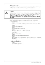
Page 7: ...rdwareorsoftwareornon observanceofthewarninginstruc tions contained in this manual or attached to the product may result in serious damage injury to property and persons Only those auxiliary units and expansion units recommended by MITSUBISHI ELECTRIC may be used together with the SD and SQ robot systems Any and all other use is determined as not in accordance to the instructions The industrial ro...

Page 8: ...0 0551 Regulations for transformers VDE 0700 Safety of electrical devices for domestic and similar uses VDE 0860 Safety regulations for mains operated electronic devices and their accessories for domestic and similar uses Fire protection regulations Accident prevention regulations VBG No 4 Electrical plants and equipment E ATTENTION A safety manual is included with the robot This manual deals with...

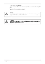
Page 9: ...f the robot The individual instructions mean the following P DANGER Meansthatthereisadangertolifeandhealthoftheuser e g fromelectricalvoltage e g when the appropriate safety measures have not been taken E ATTENTION Is a warning of possible damages to the robot its periphery or other valuable property if the appropriate safety measures are not taken ...

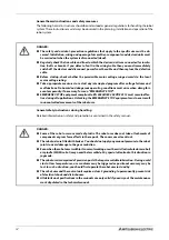
Page 10: ...rdous dangerous operating conditions must arise when doing this even temporarily If necessary force an EMERGENCY STOP EMERGENCY STOP equipment compliant to EN 60204 IEC 204 VDE 0113 must remain effec tive during all applications Unlocking the EMERGENCY STOP equipment must never result in uncontrolled movements of the robot arm P DANGER Some of the robot arms are made of plastic The robot arm does ...

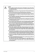
Page 11: ...and J3 axes collide with the mechanical end stops when an articulated robot is inautomaticmodethentheplasticbuffersoftheendstopsmustbereplaced Otherwise the reduction gearing may be severely damaged on the next collision Please contact your Mitsubishi partner to replace the buffers When the power supply is interrupted then the brakes grip the robot arm If this happens the robot arm may deviate fro...

Page 12: ...structions are steps that must be carried out in their exact sequence during startup op eration maintenance and similar operations They are numbered consecutively black numbers in white circles Text Text Text Use of footnotes in tables Instructionsintablesareexplainedinfootnotesunderneaththetables insuperscript Thereisafoot note character at the appropriate position in the table in superscript Ift...

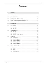
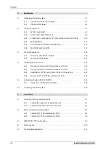
Page 13: ...e of delivery 2 1 2 1 1 SD series 2 1 2 1 2 SQ series 2 2 2 2 System configuration 2 3 2 2 1 SD series 2 3 2 2 2 SQ series 2 4 2 2 3 Components of the robot arm 2 5 2 3 Control units 2 8 2 3 1 Control panel 2 8 2 3 2 CR1DA components 2 10 2 3 3 CR2DA components 2 11 2 3 4 CR1QA components 2 13 2 3 5 CR2QA components 2 14 2 4 Robot CPU SQ series only 2 15 2 5 Teaching Box 2 16 2 5 1 R28TB 2 16 2 5 ...

Page 14: ...nsport control unit CR1DA and drive unit DU1A 3 22 3 4 2 Transport control unit CR2DA and drive unit DU2A 3 22 3 4 3 Installing the CR1DA control unit and the DU1A drive unit 3 23 3 4 4 Set up control unit CR2DA and drive unit DU2A 3 24 3 5 Installation of robot CPU Q172DRCPU 3 25 3 5 1 Installation and removal of modules 3 26 3 6 Grounding the robot system 3 28 4 Connection 4 1 Connection of the ...

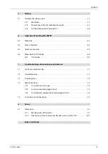
Page 15: ...OG mode 6 9 6 4 1 JOG modes 6 9 7 Troubleshooting and maintenance instructions 7 1 Faults in automatic mode 7 1 7 2 Troubleshooting 7 1 7 3 Error diagnosis 7 2 7 4 Replace the fuses 7 3 7 4 1 Fuse and error messages 7 3 7 4 2 Fuse for pneumatic gripper hand 7 3 7 4 3 Fuse of power supply of pneumatic gripper hand 7 4 7 5 Instructions on maintenance 7 5 A Annex A 1 Dimensions A 1 A 1 1 Working area...

Page 16: ...Contents X ...

Page 17: ...manual is a translation of the original German manual from MITSUBISHI ELECTRIC B V The operating steps shown in this manual refer to the Teaching Box R32TB This manual applies to the following robots and control units Series Model Construction Handling weight kg Control unit SD RV 2SDB Vertical articulated arm 2 CR1DA RV 3SDB 3SDJB 3 RV 6SD 6SDL 6 CR2DA RV 12SD 12SDL 12 RH 6SDH SCARA 6 CR1DA RH 12...

Page 18: ...xis model L long arm model empty J4 and J6 are not equipped with a brake B all axes with brake Series SD SD series SQ SQ series Load bearing capacity in kg RV vertical articulated arm robot RH 6SDH 35 20 C SMxx Sxx special model SM specially protected control unit empty standard model C clean room model M splash proof model Arm lengths of ballscrew e g 30 300 mm 35 350 mm Arm lengths e g 55 550 mm...

Page 19: ...el name of the SCARA robot for ceiling mounting RH 3SDH R 35 15 Sxx Sxx special model Arm lengths of ballscrew e g 15 150 mm Arm lengths e g 35 350 mm Installation posture Hanging Series SDH SDH Serie SQH SQH Serie Load bearing capacity in kg RH SCARA robot ...

Page 20: ...tivities when operating the robot must be clearly defined and observed to ensure that there are no unclarities or unclear duties regarding the safety aspects For all work relating to the installation startup equipping fitting operation changes to oper ating conditions and modes of operation maintenance inspection and repairs the switch off procedures stipulated in the manual must be observed The p...

Page 21: ...here are large frequency inverters transformers magnetic switches or welding devices in the vicinity there are radios or televisions in the vicinity Temperature Humidity Do not use when the ambient temperature is above 40 C or below 0 C the robot is subjected to direct sunlight the air humidity is below 45 or above 85 condensation can occur Vibrations Do not use when the robot is subjected to heav...

Page 22: ...Performance Level PL compliant with EN ISO 13849 1 Introduction 1 6 ...

Page 23: ...or basic operation of the robot are described in this chapter Options and spare parts are listed in the technical manual 2 1 Scope of delivery 2 1 1 SD series R001430E Fig 2 1 Scope of delivery of robot systems RV SD and RH SDH 5 axis articulated arm SCARA Fixing screws with washers and snap rings Transport locks Technical documentation Control unit Cable set 6 axis articulated arm or or ...

Page 24: ... SQ series R001431E Fig 2 2 Scope of delivery of robot systems RV SQ and RH SQH 5 axis articulated arm SCARA Fixing screws with washers and snap rings Transport locks Technical documentation Drive unit 6 axis articulated arm or or Cable set CPU ...

Page 25: ...ed for the basic configuration of a robot system 2 2 1 SD series R001778E Fig 2 3 Configuration of an SD series robot system NOTE The Teaching Box is an optional extra It is required for manual operation of the robot 5 axis articulated arm 6 axis articulated arm SCARA Cable set Control unit Teaching Box R32TB optional or or ...

Page 26: ...79E Fig 2 4 Configuration of an SQ series robot system NOTE The Teaching Box is an optional extra It is required for manual operation of the robot 5 axis articulated arm 6 axis articulated arm SCARA Cable set Drive unit Teaching Box R32TB optional Robot CPU or or ...

Page 27: ...s of the robot arm on the vertical articulated arm robot Name of axis Meaning J1 axis Base axis J2 axis Shoulder axis J3 axis Elbow axis J4 axis Rotating forearm axis J5 axis Wrist tilting axis J6 axis Wrist rotating axis Tab 2 1 Overview of axis names J3 axis J6 axis Wrist J4 axis Forearm Elbow block Upper arm J2 axis Base J1 axis Shoulder J5 axis Elbow ...

Page 28: ...System configuration System overview 2 6 R001433E Fig 2 6 Components of the robot arm on the SCARA for floor mounting J2 axis J3 axis Ball screw Arm 1 Arm 2 Base J1 axis J4 axis ...

Page 29: ...System overview System configuration SD SQ series 2 7 R001780E Fig 2 7 Components of the robot arm on the SCARA for ceiling mounting J2 axis J3 axis Shaft Arm 1 No 2 arm Base J1 axis J4 axis ...

Page 30: ... EMG STOP pushbutton switch The pushbutton switch is used for the EMERGENCY STOP of the robot system After pressing the pushbutton switch the servo power supply is switched off immediately and the moving robot arm stops instan taneously The pushbutton is unlocked by turning it to the right and then jumps back out CHNG DISP key Changes the display on the control unit in the following order Program ...

Page 31: ...manual of the robot MANUAL If the Teaching Box is enabled then the robot can only be operated by the Teaching Box Operation cannot be carried out using exter nal signals or the control unit UP DOWN key Scrolls within the display T B connection Port to connect the Teaching Box Install the dummy plug in the port do this with the control unit turned off if you do not plan to connect the Teaching Box ...

Page 32: ...N Connection for EMERGENCY STOP pushbutton or circuit SLOT1 Slot for optional plug in cards Connection of a parallel input output ports RIO Port to connect an additional parallel input output ports Additional stop input SKIP Additional robot stop Expansion memory connection Connection for an optional memory cassette Port or conveyor belt tracking CNENC Connection of up to 2 encoders for conveyor b...

Page 33: ...l cable CN2 Robot control cable Input for EMERGENCY STOP pushbutton EMGIN Connection for EMERGENCY STOP pushbutton Output for EMERGENCY STOP state EMGOUT Output of current EMERGENCY STOP state Slot for hand interface card HND Slot for installing the interface card for the pneumatically operated gripper hand SLOT1 Slots for optional plug in cards SLOT2 SLOT3 Tab 2 4 Components on the rear of the CR...

Page 34: ...ort Ethernet connection LAN1 Port to connect an ethernet cable For the CE approved version use the filter and ferrite core supplied with the equipment Port or conveyor belt tracking CNENC Connection of encoder cable for conveyor belt tracking Additional stop input SKIP Additional robot stop Grounding screw 5 x Grounding connector No Name Function Tab 2 4 Components on the rear of the CR2DA control...

Page 35: ...le CN2 Robot control cable Input for EMERGENCY STOP pushbutton EMGIN Connection for EMERGENCY STOP pushbutton or circuit Output for EMERGENCY STOP state EMGOUT Output of current EMERGENCY STOP state Slot for hand interface card HND Slot for installing the interface card for the pneumatically operated gripper hand Additional stop input SKIP Additional robot stop OPT1A CPU connections CON3 DCOUT CND...

Page 36: ...nnection for signal cable CN2 Robot control cable Input for EMERGENCY STOP push button EMGIN Connection for EMERGENCY STOP pushbutton Output for EMERGENCY STOP state EMGOUT Output of current EMERGENCY STOP state Slot for hand interface card HND Slot for installing the interface card for the pneumatically operated gripper hand Additional stop input SKIP Additional robot stop OPT1A CPU connections C...

Page 37: ... LED display Status and alarm display Code switch SW1 Setting the operating mode Must be set to 0 Code switch SW2 RUN STOP selector switch Not used EMI EMERGENCY STOP input All servo motors can be stopped simultaneously via this input EMI ON stop EMERGENCY STOP enabled EMI OFF connect 24 V DC EMERGENCY STOP disabled CN1 Connection of control unit CN2 Connection of an additional axis up to 8 axes L...

Page 38: ...Teaching Box System overview 2 16 2 5 Teaching Box 2 5 1 R28TB R000743E Fig 2 14 Views of Teaching Box R28TB Weight approx 0 5 kg ...

Page 39: ...D key Forward steps are executed together with the INP EXE key The next program line in edit mode is displayed Press the key together with the STEP MOVE key to increase override BACKWD key Reverse steps are executed together with the INP EXE key The previous program line in edit mode is displayed Press the key together with the STEP MOVE key to decrease override COND key Edit the program ERROR RES...

Page 40: ...s of the program or the robot arm is displayed on the LCD Status display The LED displays the status of the robot or the Teaching Box F1 F2 F3 F4 key Run the functions currently shown on the display FUNCTION key Toggle the displayed functions STOP key Cancel the running program and stop the robot This function is the same as the function of the STOP key on the control panel of the control unit Thi...

Page 41: ...de and pops up the hand menu CHARACTER key Calls up the Edit menu and switches between numbers and letters e g when edit ing position data RESET key Acknowledges an error code A program is reset when used together with the EXE key key Moves the cursor in the appropriate direction CLEAR key Deletes the character at the cursor position EXE key Enter data or move the robot in direct mode Data key Ove...

Page 42: ...switch with locking function for EMERGENCY STOP After pressing this the robot is immediately stopped irrespective of the respective operating condition The pushbutton is once more unlocked by turning it to the right Stylus inserted into housing The touchscreen can be operated with this stylus It is contained in a slot in the housing of the operator device and should be stored there after being use...

Page 43: ...lds using these arrow keys OK key Accept the settings in the current menu or entry field using this key CANCEL key Reject the settings in the current menu or entry field using this key Multi grip hand gripper The multi grip hand gripper provides for a sure and comfortable grip of the opera tor device and is suitable both for right and left handed operation Three step switch The three step enable s...

Page 44: ...Teaching Box System overview 2 22 ...

Page 45: ... the floor as shown in Use a knife or similar object to open the packaging tape Pull the inner packaging out of the box horizontally as shown in Set the robot arm upright together with the inner packaging as shown in Open the inner packaging as shown in and remove the robot Transport the robot arm to the place of installation as described in Section 3 2 E ATTENTION Always unpack the robot only on ...

Page 46: ... tape as shown in Using both hands remove the upper part of the packaging as shown in Remove the four screws with which the base is screwed onto the lower section Transport the robot arm to the place of installation as described in Section 3 2 NOTE Keep the packaging and transport locks for later transport R001296C Fig 3 2 Unpack articulated arm robot RV 3SD SDJ RV 6SD 6SDL RV 3SQ 3SQJ and RV 6SQ ...

Page 47: ...en surface To open remove the nails from the wooden frame Remove the wooden frame and the packaging material Remove the four fixing screws with which the base is screwed onto the wooden frame Transport the robot arm to the place of installation as described in Section 3 2 NOTE Keep the packaging and transport locks for later transport R001458E Fig 3 3 Unpack articulated arm robot RV 12SD SDL and R...

Page 48: ...fe or similar object to open the packaging tape as shown in Remove Part A of the packaging as shown in Remove the four fixing screws with which the base is screwed onto the wooden frame see Transport the robot arm to the place of installation as described in Section 3 2 NOTE Keep the packaging and transport locks for later transport R001368E Fig 3 4 Unpack the SCARA robot Packing tape Robot arm Tr...

Page 49: ...rdboard in the inside Open the vinyl and confirm the hanging tools two places Hang the hook of the crane here Two places Hoistwiththecraneandseparatetherobotarmtogetherwithpackingmaterialfromthepackingbox Cut with scissors etc tape which fixed packing material and remove packing material Transport the robot arm to the place of installation as described in Section 3 2 E ATTENTION Don t remove fixin...

Page 50: ...3SQHR Packing box Tape Upper cover Packing material Cardboard Robot arm base section Hanging tools Packing material Tape Fixingplate Cut the tape Remove the upper cover Remove the packing material Open the vinyl Hang the hook of the crane Hoist with crane and remove the packing material Completion ...

Page 51: ...ing points are only for brief lifting pur poses Take care to prevent impacts to the robot arm during transport E ATTENTION When carrying the robot arm always hold it by the designated holding points and Never try to lift the robot arm by its covers as this can cause damage NOTE Keep the transport locks and their fastening screws in a safe place for later transport R001764E Fig 3 6 Transporting the...

Page 52: ...oy the robot arm E ATTENTION Two persons are always required to transport the robot arm The transport locks must not be removed before transport Always carry the robot arm at holding points and Never carry the robot arm at the covers because this may result in damages NOTE Keep the transport locks and their fixing screws in a safe place for any later transport R001297E Fig 3 7 Transport 5 axis rob...

Page 53: ... dolly if transporting longer distances Only carry at the holding points for short periods of time Avoid knocks impact loads when transporting the robot arm R001298E Fig 3 8 Transport 6 axis robot arm RV 3SD or RV 3SQ E ATTENTION Only remove the transport locks after installing the robot arm Transport lock J1 Upper arm Base Front view Shoulder Transport lock Side view ...

Page 54: ... transport angel after transport E ATTENTION Always use a crane to transport the robot arm The transport lock must not be removed before transport The fixing screws of the transport lock and the transport bracket must be removed after transport NOTE Keep the transport lock the transport angle and their appropriate fixing screws in a safe place for any later transport E ATTENTION To avoid faults th...

Page 55: ...Installation Transport robot arm SD SQ series 3 11 R001137E Fig 3 9 Fix the transport bracket Transport lock Eyes Transport bracket Wire rope Transport lock Allen head screws ...

Page 56: ...e a dolly if transporting longer distances Only carry at the holding points for short periods of time Do not strain any covers Avoid knocks impact loads when transporting the robot arm Only remove the transport locks after installing the robot arm E ATTENTION The transport locks must not be removed before transport Two persons are always required to carry the robot arm Always carry the robot arm a...

Page 57: ...the crane must be attached as shown in Fig 3 11 Always use four supporting ropes to transport the robot with a crane NOTE Keep the transport and support brackets as well as the transport locks and their fixing screws in a safe place for any later transport R001370E Fig 3 11 Fix the transport suspensions E ATTENTION Alsoobservetheabove mentionedstepswhentransportingtherobotatalatertime e g when cha...

Page 58: ...TION Always use a crane to transport the robot arm The transport lock must not be removed before transport Transport carefully so that the robot may not tilt by using two wires Take care sufficiently not to give the interference and the shock with the installation stage etc NOTE Keep the hanging tools as well as the transport locks and their fixing screws in a safe place for any later transport R0...

Page 59: ...9 5 mm upper end J4 Not fixed Tab 3 1 Transportation posture E ATTENTION Alsoobservetheabove mentionedstepswhentransportingtherobotatalatertime e g when changing the installation location If the robot is transported without the attached transport locks or if it is transported in operating position then dangerous situations might arise due to a shifting of the centre of gravity during transport ...

Page 60: ...atno distortioncanoccur evenfromtheloadsandvibrations emanating from the robot itself Only remove the transport locks after setting up the robot arm If the robot is mounted on the ceiling then the MEGDIR parameter must be changed Additional information on this parameter is contained in the operation and programming instructions of the control units High loads and strains occur on the base area whe...

Page 61: ...00 Tab 3 3 Reaction forces on the base area of the robot E ATTENTION When installing the robot make sure that there is enough space remaining at the rear of the robot arm to connect the cable used and to replace the backup battery Robot arm Fixture View from below Tab 3 2 Set up the robot arm 2 㧲 㨂 㧲 㧴 㧲 㧴 㧲 㧴 㧲 㧴 㧹㧸 㧹㧸 㧲 㨂 㧹㨀 Fixing screws 4 M8 x 40 Allen screw Snap ring Washer Installation side ...

Page 62: ...sesaswellastherobot arm itself should be installed on a common assembly platform area The baseareamustbedesignedsothatno distortioncanoccur evenfromtheloadsandvibrations emanating from the robot itself Only remove the transport locks suspensions and supporting brackets after setting up the robot arm High loads and strains occur on the base area when operating the robot at high speeds Make sure tha...

Page 63: ... MT Nm 410 1440 Translational forces on horizontal plane FH N 920 1900 Translational forces on vertical plane FV N 570 1280 Tab 3 5 Reaction forces on the base area of the robot E ATTENTION When installing the robot make sure that there is enough space remaining at the rear of the robot arm to connect the cable used and to replace the backup battery ...

Page 64: ...lation surface must be designed so that no distortion can occur even from the loads and vibrations emanating from the robot itself Only remove the transport locks and hanging tools after setting up the robot arm High loads and strains occur on the installation surface when operating the robot at high speeds Make sure that the base area is suitable for the high forces and moments as listed in Tab 3...

Page 65: ...nal forces on horizontal plane FH N 920 Translational forces on vertical plane FV N 570 Tab 3 7 Reaction forces on the installation surface of the robot E ATTENTION When installing the robot make sure that there is enough space remaining at the rear of the robot arm to connect the cable used and at the side to replace the backup battery ...

Page 66: ... in the illustration below Lift it by holding firmly below the front or rear edges Do not attempt to lift the unit by the switches or connectors R001767E Fig 3 14 Transport control units CR1DA and drive units DU1A E ATTENTION Two persons are always required to carry the control unit or the drive unit To lift take hold of the front side and the rear side Never carry the control unit or the drive un...

Page 67: ...tallation of the control unit and or drive unit if necessary Do not block the air vents at the bottom of the control unit or drive unit To ensure adequate ventilation install the units on the plastic feet provided or install spacers if you bolt the units into place Make sure that there is at least 50 mm of free space on the left of the unit at least 20 mm on the right and at least 170 mm at the re...

Page 68: ... or the drive unit from you MITSUBISHI sales agent Do not block the ventilation openings on the base of the control unit or the drive unit Make sure that there is a clearance of at least 7 mm under the unit To do this place the unit on it plastic feet or use the spacers if you screw the unit into place Make sure that there is a lateral clearance of at least 145 mm and a clearance to the rear of at...

Page 69: ...a device in the control cabinet that generates severe disturbances and heat and this device isinstalled infront ofthe robot CPU then a distance ofatleast 100mm must be maintained between this device and the CPU The device could be installed e g on the inside of the control cabinet If the robot CPU and such a device are assembled next to each other then they must have a minimum clearance of 50 mm R...

Page 70: ...odule onto the rack until it is lying fully onto the rack Additionally secure the module with a screw M3 x 12 if vibrations are to be expected This screw is not supplied with the module The robot CPU must always be secured with a fixing screw E ATTENTION The mains voltage must always be switched off before installing a module If the module is not placed correctly over the catch on the rack then th...

Page 71: ...e guide Otherwise the mounting devices on the module may be damaged QH0008E Fig 3 22 Removal of the module E ATTENTION When removing the robot CPU please note that the heat sink of the module may be very hot There is a possible risk of burns Slot Module Rack Toremovethemodule hold itinbothhandsand press the upper catch downwards With the catch pressed tilt the module down wards slightly The lower ...

Page 72: ...in Section 4 2 If possible the grounding of the robot arm must be separated from other units devices Theminimum cross section of thegrounding cable must be 2 0 mm RV 2SD RV 2SQ or 3 5 mm all other models The grounding cable is not included in the scope of delivery of the robot system The grounding cable should be kept as short as possible R000451E Fig 3 23 Grounding the robot system Robot arm sepa...

Page 73: ...ounding screw M4 x 10 to the grounding connection of the robot arm see here Fig 3 24 R001300E R001457E Fig 3 24 Grounding the robot arm Articulated arm robot SCARA robot RH 6SDH 12SDH 20SDH and RH 6SQH 12SQH 20SQH robot arm grounding connection with at least 2 0 mm RV 2SD RV 2SQ or 3 5 mm all other models not included in scope of delivery grounding screw M4 x 10 grounding screw M4 x 10 A SCARA rob...

Page 74: ...Grounding the robot system Installation 3 30 ...

Page 75: ...nection of the Teaching Box 4 1 Connection of the connection cable 4 1 1 Connect the robot arm to the control unit The following figure shows the connection of the connection cable between the robot arm and the control unit R001769E Fig 4 1 Connection of the connection cable CN1 CN2 CN2 CN1 CR1D 700 controller CN1 CN2 Controller CR2D 700 Robot arm Signal cable CN2 Control cable CN1 CR2DA or DU2A C...

Page 76: ...e locking mechanism on the plug downwards The plug can not be pulled out in this position To release the connection press the locking mechanism upwards The plug can be removed in this position R001085C Fig 4 2 Detailed view of the locking mechanism NOTE The shape of the plugs is different for control cable and power cable If connected incorrectly the plug may be damaged E ATTENTION The standard co...

Page 77: ...sult in an irritation to the eyes if viewed directly R001509E Fig 4 3 Connection of robot CPU to drive unit DU1A NOTE Connect the shielding of the TU cable to the grounding cable on the housing of the drive unit to prevent electromagnetic disturbances Remove20to 30 mm of wireinsulationfrom the TU cableand connect the shielding to the grounding terminal on the rear of the drive unit Wire insulation...

Page 78: ...ritation to the eyes if viewed directly R001509E Fig 4 4 Connection of robot CPU to drive unit DU2A NOTE Connect the shielding of the TU cable to the grounding cable on the housing of the drive unit to prevent electromagnetic disturbances Remove20to 30mmof wireinsulationfrom the TU cableand connect the shielding to the grounding terminal on the rear of the drive unit Wire insulation DU2A drive uni...

Page 79: ...upplycablefromtheoutputterminalsofthecircuitbreaker to terminals L1 and L2 in the power connection terminals block Connect the grounding cable with the grounding cable marked PE to the housing of the control unit Connect the power supply to the input terminals of the circuit breaker Routethepowersupplycablethroughthecableopening andsecureitwithstrainreliefclamp Reinstall the covers on the terminal...

Page 80: ... mains line feed and the grounding cable Use cable with a minimum cross section of 2 5 mm Connect the mains line to the terminals of the power switch according to Fig 4 6 Connect the grounding cable with the grounding cable marked PE to the housing of the control unit Fix the terminal cover of the power switch back into place You will hear a click when it locks in lay the mains line through the ca...

Page 81: ...t The EMERGENCY STOP inputs are normally blank see Fig 4 8 The EMERGENCY STOP pushbutton the door closing contact and the enable switch enabling unit must be connected by the user R001771E Fig 4 7 Connection for EMERGENCY STOP circuit Control unit CR2DA or drive unit DU2A EMGIN Ferrite core 30 cm EMGOUT Control unit CR1DA or drive unit DU1A 30 cm Ferrite core EMGIN ...

Page 82: ... Output for control of auxiliary axis AXMC1 Output for robot error message Output for operating mode Output for control of auxiliary axis AXMC2 24 GND 24 GND 24 GND 24 GND 24 GND 24 GND 24 V 24 V 24 V 24 V 24 V 24 V Relay Relay Relay Relay Relay Relay Wire bridge EMERGENCY STOP switch Door closing contact Enable switch Wire bridge Wire bridge EMERGENCY STOP switch Door closing contact Enable switc...

Page 83: ...enable switch to terminals 10A 11A 10B 11B an Plug the twisted ends of the line into the connection terminal Pull the screwdriver out of the locking mechanism R001465E Fig 4 10 Connection to the terminals E ATTENTION Connect the EMERGENCY STOP switch at an easily accessible location near the robot If the robot behaves erratically then you must stop it immediately Twist the lines carefully when con...

Page 84: ... 9A 9B 1A 1B 2A 2B 3A 3B 4A 4B 10A 10B 11A 11B 5A 5B 6A 6B EMGIN1 2 EMGIN1 2 EMGOUT1 2 EMGOUT1 2 RA RA RA RA RA RA RA RA RA RA RA RA Control unit 1 Control unit 2 EMERGENCY STOP control unit EMERGENCY STOP Teaching Box Internal safety circuit Control output Auxiliary axes EMERGENCY STOP control unit EMERGENCY STOP Teaching Box Internal safety circuit Control output Auxiliary axis Unassigned Unassi...

Page 85: ... been omitted from the figure the figure therefore devi ates from the actual conditions of the product 1A 1B 2A 2B 3A 3B 4A 4B 5A 5B 6A 6B 8A 8B 9A 9B 1A 1B 2A 2B 3A 3B 4A 4B 10A 10B 11A 11B 5A 5B 6A 6B EMGIN1 2 EMGIN1 2 EMGOUT1 2 EMGOUT1 2 RA RA RA RA RA RA RA Control unit 1 EMERGENCY STOP control unit EMERGENCY STOP Teaching Box Internal safety circuit Control output Auxiliary axes Input door co...

Page 86: ... output O Operating mode output O External relay connection Tab 4 2 Inputs and outputs R001516E Fig 4 13 Signal flow plan Output for system EMERGENCY STOP Operating mode Teach Auto open closed ON closed open closed open ON ON ON Door contact output Servo ON mode Teaching Box ENABLE switch Teaching Box Enable switch EMERGENCY STOP IO control unit Robot amplifier EMG ...

Page 87: ...onnection of the control unit or the drive unit Thelockoftheconnectormustpointupwards Youhearaclickwhentheconnectioniscorrect Release the connection between the control unit or drive unit and the Teaching Box Switch off the control unit or the drive unit Lift the lock upwards on the Teaching Box plug connector Take hold of the plug in Area B and pull it upwards and out Install the dummy plug if yo...

Page 88: ...Teaching Box connection Connection 4 14 ...

Page 89: ...nd save the home position 5 1 2 Prepare the system for maintenance mode Thepreparationstobemadeforcalling upthemaintenancemenuaredescribedinthefollowingsec tion E ATTENTION To ensure perfect function of the robot the home position must first be set and must always be carried out after unpacking or reconfiguring robot arm or control unit Step 1 Switch on the supply voltage P DANGER Make sure that t...

Page 90: ... NOTE As long as the serial number is not input in parameter RBSERIAL error message C0150 is issued when the power supply of the control unit or the drive unit with the robot CPU CPU Q172DRCPU is turned on In this case enter the serial number of the robot arm in the RBSERIAL parameter How to enter the serial number in the parameter is described in step 3 POWER switch Control unit CR2D A or drive u...

Page 91: ... 2 Set MODE switch to MANUAL R001469E Fig 5 3 Switch on the Teaching Box E ATTENTION To gain sole control of the robot system you must set the ENABLE DISABLE switch of the Teaching Box to the ENABLE position The control functions at the control unit are disabled in thisstate Forsafetyreasons allEMERGENCY STOPandSTOPswitchesonthesystemarealways active MODE MANUAL AUTOMATIC 下 ENABLE ランプ点灯 上 DISABLE ...

Page 92: ... of the robot arm Press the EXE key to confirm the entry A beep is issued and the value is stored Step 3 Enter the serial number R001831E R001832E R001472E R001473E MELFA RV 3SD Ver 1 0 CRnD 7xx COPYRIGHT C 2007 MITSUBISHI ELEC TRIC CORPORATION ALL RIGHTS RESE RVED MENU 1 FILE EDIT 2 RUN 3 PARAM 4 ORIGIN BRK 5 SET INIT 6 ENHANCED CLOSE 123 MENU 1 FILE EDIT 2 RUN 3 PARAM 4 ORIGIN BRK 5 SET INIT 6 E...

Page 93: ...series 5 5 Press the key F4 for the CLOSE box The main menu appears on the display R001474E PARAMETER NAME RBSERIAL ELE DATA XXXXXXXX ޓޓޓޓޓޓޓޓޓ ޓޓ CLOSE 123 Next DATA Prev MENU ޓޓ ޓ 1 FILE EDIT 2 RUN 3 PARAM 4 ORIGIN BRK 5 SET INIT CLOSE ޓ 123 ...

Page 94: ... the J1 cover for RH 3SDHR and RH 3SQHR on the inside of the base cover B L A detailed description on how to remove a cover is contained in the technical manual of the respec tive robot E ATTENTION The data used for the home setting of the zero point is in the Default column of the product insert If the new setting of the home position of the robot arm has been carried out e g when replacing a mot...

Page 95: ...ress key 1 to call up the ORIGIN menu Press key 1 to select the DATA method for the setting The home position setting menu is displayed Step 1 Select the setting adjustment method R001834E R001476E R001477E R001478E MENU 1 FILE EDIT 2 RUN 3 PARAM 4 ORIGIN BRK 5 SET INIT 6 ENHANCED CLOSE 123 ORIGIN BRAKE 1 ORIGIN 2 BRAKE CLOSE 123 ORIGIN 1 DATA 2 MECH 3 TOOL 4 ABS 5 USER CLOSE 123 ORIGIN DATA J1 J2...

Page 96: ...Step 2 Enter the home position R001478E Fig 5 5 Menu for setting the home position NOTES You can move the cursor on the display of the Teaching Box using keys and Enter characters by pressing the CHARACTER key first and then the key for the character The next character is displayed by repeatedly pressing the character key Numbers are entered at the numeric keypad You can delete incorrect entries b...

Page 97: ...is entered in the same way as described above Press the EXE after entering all data An acknowledgement screen pops up Press the F1 key to complete the entry of the home position R001481E R001482E R001483E R001484E R001485E ORIGIN DATA D V J1 J2 J3 J4 J5 J6 J7 J8 CLOSE 123 ORIGIN DATA D V S29 J1 J2 J3 J4 J5 J6 J7 J8 CLOSE 123 ORIGIN DATA D V S29 J1 J2 J3 J4 J5 J6 J7 J8 CLOSE 123 ORIGIN DATA D V S29...

Page 98: ...Calibrate the robot system Startup 5 10 ...

Page 99: ...T POS JNT 100 P1 X 128 56 A 180 00 Y 0 00 B 90 00 Z 845 23 C 180 00 L1 L2 FL1 7 FL2 0 Next 123 TEACH MOVE Prev PROGRAM COPY SRC NAME 1 DSR NAME CLOSE 123 PROGRAM RENAME SRC NAME 1 DST NAME CLOSE 123 MELFA CRnD 7xx Ver P2T RV 6SDL COPYRIGHT C 2008 MITSUBISHI ELEC TRIC CORPORATION ALL RIGHTS RESE RVED PROGRAM DELETE NAME 1 CLOSE 123 PROTECT NAME 1 protect COMMAND OFF DATE OFF CLOSE 123 DATA CMD a1 E...

Page 100: ...S 5 USER CLOSE 123 ORIGIN DATA D Z1K85K J1 01ag 4 J2 F 15K0 J3 01E27C J4 A 5g 4 J5 05H 30 J6 81 DA9 J7 J8 CLOSE 123 ORIGIN MECH COMPLETED J1 0 J2 0 J3 0 J4 0 J5 0 J6 0 J7 0 J8 0 CLOSE 123 ORIGIN TOOL COMPLETED J1 0 J2 0 J3 0 J4 0 J5 0 J6 0 J7 0 J8 0 CLOSE 123 PROGRAM SELECTION SELECT THE PROGRAM INTO TASK SLOT 1 OK Yes No 123 a1 CHECK TEST RUN ORIGIN DATA MECH TOOL A B D C 2 RUN menu Jog mode 2 Me...

Page 101: ...J8 0 CLOSE 123 BRAKE J1 0 J2 0 J3 0 J4 0 J5 0 J6 0 J7 0 J8 0 CLOSE 123 REL INITIALIZE 1 DATA 2 PARAMETER 3 BATTERY CLOSE 123 HOURE DATA POWER ON TIME 18 Hr BATTERY ACC 14089 Hr CLOSE 123 CLOCK DATE 08 05 07 TIME 16 04 50 CLOSE 123 VERSION R C Ver P2T T B Ver 1 2 1 CLOSE 123 E ABS USER BRAKE INITIALIZE POWER CLOCK VERSION B D C 4 ABS method 2 Battery and switch on time 3 Set date time 5 Set Initial...

Page 102: ... 0 00 0 00 0 00 0 00 CLOSE 123 CYLNDR 3 XYZ WORK COORD WORK NUMBER 1 TEACHING POINT WO X 0 00 Y 0 00 Z 0 00 DEFINE 123 TEACH WX WY SQ DIRECT JNT 100 POS 123 X 128 56 A 180 00 Y 0 00 B 90 00 Z 845 23 C 180 00 L1 L2 FL1 7 FL2 0 Next 123 TEACH MOVE Prev SQ DIRECT WORK COORD BASE SELECT BASE 1 CLOSE 123 TOOL 1 SQ Direct only SQ series 2 Workpiece coordinates 6 Enhanced Menu Tool Menu Press MANUAL butt...

Page 103: ...tom right Change the character by pressing the key repeatedly For instance pressing the ABC key repeatedly allows you to select from the following characters A B C a b c When selecting letters assigned to the same key you can move the cursor along a position by using the arrow key 쑶 The following characters are assigned to the keys key key 얖 key _ Example쑴 51 is entered as the program name To do t...

Page 104: ...ter B of string ABY is to be changed to an M resulting in the new string AMY Move the cursor with the key to the B character and press the following keys CLEAR 1 x MNO 3 x WXYZ R001491E Fig 6 4 Clear a character NOTE Pressing the CLEAR key for a longer period clears all the characters in the brackets NEW PROGRAM PROGRAM NAME CLOSE ABC NEW PROGRAM PROGRAM NAME ABY CLOSE ABC AMY ...

Page 105: ...ntrol unit to MANUAL Activate the Teaching Box by setting the ENABLE DISABLE switch of the Teaching Box to ENABLE The start screen appears after switching on After the start screen appears press EXE key to call up the main menu R001492E R001543E MODE MANUAL AUTOMATIC Top disabled Bottom enabled lights up Control unit or drive unit Teaching Box Rear of the Teaching Box MELFA CRnD 7xx Ver P2T RV 6SD...

Page 106: ...ey The FILE EDIT menu is displayed R001544E R001544E FILE EDIT 1 20 Rem 136320 1 08 04 24 17 20 32 22490 2 08 04 24 14 56 08 694 A1 08 04 24 13 05 54 2208 B1 08 04 24 13 05 54 1851 COPY 123 POSI EDIT NEW MENU 1 FILE EDIT 2 RUN 3 PARAM 4 ORIGIN BRK 5 SET INIT 6 ENHANCED CLOSE 123 FILE EDIT 1 20 Rem 136320 1 08 04 24 17 20 32 22490 2 08 04 24 14 56 08 694 A1 08 04 24 13 05 54 2208 B1 08 04 24 13 05 ...

Page 107: ... above 앫 Press the function key to switch to the tool JOG mode 앫 To move the axes press appropriate key X Y Z A B C The position of the tipped tool can be moved along the axes in the tool coordinate system in tool JOG mode The tipped tool is moved linearly The position of the robot can be rotated by keys A B and C around axes X Y and Z of the tool coordinate system without changing the position of...

Page 108: ...ontrolled Workpiece jog mode R001546E Execute the three points listed above 앫 Press the function key three times to switch to workpiece JOG mode 앫 To move the axes press appropriate key X Y Z A B C In workpiece jog mode the position of the tipped tool can be moved along the axles of the workpiece coordinate system Buttons A B and C rotate the position of the robot around the X Y and Z axles of the...

Page 109: ...ns If the robot itself is affected and it is not possible for the user to remedy the cause of the error fault then you must immediately contact your MITSUBISHI sales agent P DANGER Operationmustbestoppedimmediatelyifyouobserveslightdeviationswhenoperatingthe robot or the auxiliary equipment If immediate shutdown would result in concomitant dan gers and hazards then you must select a suitable time ...

Page 110: ...numbers the errors causes and the countermeasures are listed in the operating and pro gramming instructions If an error can not be remedied by the countermeasures listed then please contact your sales partner Fig 7 1 Design of an error message NOTE The last position of the error number may be an axis number Example Error number H0931 means overcurrent of axis J1 motor 첸 0 0 0 0 An error marked wit...

Page 111: ...7 4 2 Fuse for pneumatic gripper hand Ifyou see error message H0082 replace fuse F1 rated current 1 6 A on card RZ375 for the controller of the pneumatic gripper hand Error code Description Unit Board Module Fuse H0082 Fuse for pneumatic gripper hand defective CR1DA DU1A RZ375 F1 rated current 1 6 A CR2DA DU2A H0083 Fuse of power supply or pneumatic grip per hand defective CR1DA DU1A TZ801A F3 rat...

Page 112: ...ntrol unit CR2DA drive unit DU2A If you see error message H0083 replace fuse F5 rated current 1 6 A on board TZ352B R001773E Fig 7 3 Fuse of power supply for pneumatic gripper hand CR1DA DU1A R001496E Fig 7 4 Fuse of power supply for pneumatic gripper hand CR2DA DU2A Fuse F3 TZ801A Control unit CR1DA drive unit DU1A card TZ801A A Fuse F5 TZ352B Control unit CR2DA drive unit DU2A Front side of the ...

Page 113: ...rticulated arm robot or the J3 axis SCARA robot must be supported manually to ensure that they do not fall uncontrolled into the end stop You require the support of a second person for this Small amounts of grease may exit from the robot arm If this can result in soiling or environmental pollution then the robot should be checked regularly for loss of grease If you determine that grease is exiting...

Page 114: ...Instructions on maintenance Troubleshooting and maintenance instructions 7 6 ...

Page 115: ...ot The following figure shows the range of motion of the 5 axis robot arms RV 2SDB and RV 2SQB R001775E Fig A 1 Range of motion of robot arms RV 2SDB and RV 2SQB NOTE The working area stipulated refers to the P point of the robot arm without gripper hand Weight 19 kg All dimensions in mm ...

Page 116: ...nge of motion of the 5 axis robot arms RV 3SDJB and RV 3SQJB R001498E Fig A 2 Range of motion of robot arms RV 3SDJB and RV 3SQJB NOTE The working area stipulated refers to the P point of the robot arm without gripper hand Weight 33 kg All dimensions in mm ...

Page 117: ...s the range of motion of the 6 axis robot arms RV 3SDB and RV 3SQB R001499E Fig A 3 Range of motion of robot arms RV 3SDB and RV 3SQB NOTE The working area stipulated refers to the P point of the robot arm without gripper hand Weight 37 kg All dimensions in mm ...

Page 118: ...the range of motion of robot arms RV 6SD and RV 6SQ R001500E Fig A 4 Range of motion of robot arms RV 6SD and RV 6SQ NOTE The working area stipulated refers to the P point of the robot arm without gripper hand Weight approx 58 kg All dimensions in mm ...

Page 119: ...ows the range of motion of robot arms RV 6SDL and RV 6SQL R001501E Fig A 5 Range of motion of robot arms RV 6SDL and RV 6SQL NOTE The working area stipulated refers to the P point of the robot arm without gripper hand Weight approx 60 kg All dimensions in mm ...

Page 120: ...e range of motion of robot arms RV 12SD and RV 12SQ R001150E Fig A 6 Range of motion of robot arms RV 12SD and RV 12SQ NOTE The working area stipulated refers to the P point of the robot arm without gripper hand Weight approx 93 kg All dimensions in mm ...

Page 121: ...s the range of motion of robot arms RV 12SDL and RV 12SQL R001160E Fig A 7 Range of motion of robot arms RV 12SDL and RV 12SQL NOTE The working area stipulated refers to the P point of the robot arm without gripper hand Weight approx 98 kg All dimensions in mm ...

Page 122: ...dimensions and the range of motion of robot arms RH 6SDH3520 and RH 6SQH3520 R001409E Fig A 8 External dimensions and range of motion of robot arms RH 6SDH3520 and RH 6SQH3520 Weight 20 kg Limits of range of motion View A Installation surface All dimensions in mm ...

Page 123: ...ernal dimensions and the range of motion of robot arms RH 6SDH4520 and RH 6SQH4520 R001410E Fig A 9 External dimensions and range of motion of robot arms RH 6SDH4520 and RH 6SQH4520 All dimensions in mm Limits of range of motion View A Installation surface Weight 21 kg ...

Page 124: ...dimensions and the range of motion of robot arms RH 6SDH5520 and RH 6SQH5520 R001391E Fig A 10 External dimensions and range of motion of robot arms RH 6SDH5520 and RH 6SQH5520 Limits of range of motion View A Installation surface All dimensions in mm Weight 21 kg ...

Page 125: ...nal dimensions and the range of motion of robot arms RH 12SDH5535 and RH 12SQH5535 R001414E Fig A 11 External dimensions and range of motion of robot arms RH 12SDH5535 and RH 12SQH5535 All dimensions in mm Limits of range of motion View A Installation surface Weight 41 kg ...

Page 126: ...mensions and the range of motion of robot arms RH 12SDH7035 and RH 12SQH7035 R001415E Fig A 12 External dimensions and range of motion of robot arms RH 12SDH7035 and RH 12SQH7035 All dimensions in mm Limits of range of motion View A Installation surface Weight 43 kg ...

Page 127: ...ows the external dimensions and the range of motion of robot arms RH 12SDH8535 and RH 12SQH8535 R001392E Fig A 13 External dimensions and range of motion of robot arms RH 12SDH8535 and RH 12SQH8535 All dimensions in mm View A Installation surface Weight 45 kg ...

Page 128: ...and RH 20SQH8545 R001776E Fig A 14 External dimensions and range of motion of robot arms RH 20SDH8535 RH 20SDH8545 RH 20SQH8535 and RH 20SQH8545 A All dimensions in mm View A Installation surface Weight RH 20SDH8535 20SQH8535 47 kg RH 20SDH8545 20SQH8545 48 kg Robots L1 L2 L3 RH 20SDH8535 RH 20SQH8535 967 350 10 RH 20SDH8545 RH 20SQH8545 1067 450 110 ...

Page 129: ...H10045 R001777E Fig A 15 External dimensions and range of motion of robot arms RH 20SDH10035 RH 20SDH10045 RH 20SQH10035 and RH 20SQH10045 All dimensions in mm View A Installation surface Weight RH 20SDH10035 20SQH10035 50 kg RH 20SDH10045 20SQH10045 51 kg Robots L1 L2 L3 RH 20SDH10035 RH 20SQH10035 967 350 10 RH 20SDH10045 RH 20SQH10045 1067 450 110 Limits of range of motion ...

Page 130: ...A Installations oberfläche Weight 24 kg Grenzen des Bewegungsbereichs All dimensions in mm Operating range diagram No 1 arm circle radius The locus of J4 axis center The locus of J2 axis center Detailed drawing of T slot Maintenance space Installation reference Installation reference Maintenance space 4 Ø9 Installation hole 2 M12 hole for hanging tools 4 M8 hole for the jack up View A View B Robot...

Page 131: ... series A 17 A 1 2 Dimensions of the control units the drive units and the CPU Control unit CR1DA and drive unit DU1A R002090E Fig A 17 Dimensions of control unit CR1DA and drive unit DU1A All dimensions in mm Weight ca 9 kg ...

Page 132: ...Dimensions Annex A 18 Control unit CR2DA and drive unit DU2A R001982E Fig A 18 Dimensions of control unit CR2DA and drive unit DU2A All dimensions in mm Weight CR2DA approx 21 kg DU2A approx 20 kg ...

Page 133: ...Annex Dimensions SD SQ series A 19 Robot CPU Q172DRCPU R001508E Fig A 19 Dimensions of robot CPU Q172DRCPU All dimensions in mm Weight 0 33 kg ...

Page 134: ...Dimensions Annex A 20 ...

Page 135: ...ounding the control unit 4 5 robot arm 3 29 robot system 3 28 I Installation 3 1 J JOG modes 6 9 M Mains connection 4 5 Maintenance instructions 7 5 Menu tree 6 1 Move robot 6 9 O Overview Control units 1 1 Robot models 1 1 Overview of models 1 1 R Remedy fault 7 1 Replace fuse 7 3 Robot arm Components 2 5 Robot arms Overview of models 1 1 S SCARA robot 2 6 Scope of delivery SD series 2 1 SQ serie...

Page 136: ...A 22 Index Annex ...

Page 137: ......

Page 138: ......

Page 139: ......

Page 140: ......

Page 141: ......

Page 142: ......

Page 143: ......

Page 144: ......

Page 145: ......

Page 146: ......

Page 147: ......

Page 148: ......

Page 149: ......

Page 150: ......

Page 151: ......

Page 152: ......

Page 153: ......

Page 154: ......

Page 155: ......

Page 156: ......

Page 157: ......

Page 158: ......

Page 159: ......

Page 160: ......

Page 161: ......

Page 162: ......

Page 163: ......

Page 164: ......

Page 165: ......

Page 166: ......

Page 167: ......

Page 168: ......

Page 169: ......

Page 170: ......

Page 171: ......

Page 172: ......

Page 173: ......

Page 174: ......

Page 175: ......

Page 176: ......

Page 177: ......

Page 178: ......

Page 179: ......

Page 180: ......

Page 181: ......

Page 182: ......

Page 183: ......

Page 184: ......

Page 185: ......

Page 186: ...oie 37 FIN 28400 Ulvila Phone 358 0 207 463 540 Fax 358 0 207 463 541 GREECE UTECO 5 Mavrogenous Str GR 18542 Piraeus Phone 30 211 1206 900 Fax 30 211 1206 999 HUNGARY AXICONT AUTOMATIKA Kft ROBOT CENTER Reitter F U 132 HU 1131 Budapest Phone 36 1 412 0882 Fax 36 1 412 0883 MALTA ALFATRADE Ltd 99 Paola Hill Malta Paola PLA 1702 Phone 356 0 21 697 816 Fax 356 0 21 697 817 NETHERLANDS HIFLEX AUTOM T...

Reviews: