background image

CONTENTS

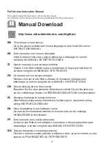
Full Version Instruction Manual ...................................................................2
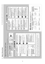
1.  Safety Precautions .................................................................................3
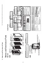
2.  Names and Functions of Parts ...............................................................4
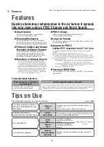
3.  Features .................................................................................................5

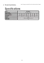
4.  Product Specifications

 ............................................................................6

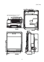
5.  External Dimensions ..............................................................................7
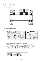
6.  Electrical Wiring Diagram .......................................................................9
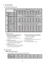
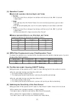
7.  Control Outline .....................................................................................10
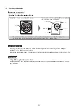
8.  Technical Points ...................................................................................13
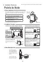
9.  Installation Procedures .........................................................................14
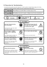
10. Precautions for Troubleshooting ...........................................................15
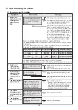
11. Troubleshooting Procedures ................................................................16
12. Troubleshooting ....................................................................................21
13. Routine Inspection and Maintenance ...................................................22
14. Service Inspection List .........................................................................26
15. Precautions for Disassembly and Reassembly ....................................27
16. Disassembly and Reassembly .............................................................29
17. Parts Catalog ........................................................................................36

AIR PURIFIER

 2020

SERVICE MANUAL 

No.MAW-E-20010


Model


MA-E85R-E

Sold from 2020

Summary of Contents for MA-E85R-E

Page 1: ...utline 10 8 Technical Points 13 9 Installation Procedures 14 10 Precautions for Troubleshooting 15 11 Troubleshooting Procedures 16 12 Troubleshooting 21 13 Routine Inspection and Maintenance 22 14 Service Inspection List 26 15 Precautions for Disassembly and Reassembly 27 16 Disassembly and Reassembly 29 17 Parts Catalog 36 AIR PURIFIER 2020 SERVICE MANUAL No MAW E 20010 Model MA E85R E Sold from...

Page 2: ...ersion abrégée Rendez vous sur le site Web ci dessus et choisissez la langue pour télécharger la version complète de la MANUEL D INSTRUCTIONS DE Diese Anleitung ist eine Kurzversion Besuchen Sie die oben stehende Website und wählen Sie die Sprache aus um die vollständige Version von BEDIENUNGSANLEITUNG herunterzuladen PL Niniejsza instrukcja to wersja skrócona Odwiedź powyższą stronę internetową i...

Page 3: ...y cause the unit to topple or fall and cause injury Do not lay the unit horizontally when removing a filter This may cause dust to enter inside resulting in fire or electric shock Do not use a damaged filter or operate the unit while a filter is removed This may cause dust to enter inside resulting in fire or electric shock Do not install the unit where water may be spilt onto it or where there is...

Page 4: ...num which exhibits high chemical reactivity with a catalytic substance that has numerous nano sized pores It absorbs and breaks down the sources of various odorants causing complex odors in daily life that are difficult to sense High Efficiency Particulate Air filter A highly efficient filter capable of filtering at least 99 97 of particles with a diameter of 0 3 μm micrometer What is a platinum c...

Page 5: ...from 0 1 to 2 5 μm Consideration is not given to new particles entering from outdoors due to for example ventilation z PM2 5 is a generic term for fine particulate matter of 2 5 μm or less z The removal of fine particulate matter less than 0 1 μm with this air purifier has not been verified Also this air purifier is not capable of removing all harmful substances from the air z This is the effect a...

Page 6: ...Turbo High Middle Low Silent Power consumption 86 W 23 W 11 W 8 W 6 W Air volume 510 m3 h 306 m3 h 204 m3 h 150 m3 h 102 m3 h Weight 9 9 kg Dimensions 547 H 425 W 244 D mm Cord length 1 8 m 4 Product Specifications Note This page is extracted from the full version instruction manual ...

Page 7: ...7 5 External Dimensions Unit mm 425 mm 244 mm 547 mm ...

Page 8: ...517 425 547 390 17 5 277 5 46 Front view Right side view Caution nameplate Back view Top view Effective length 1800 Power cord Unit nameplate Metal mesh inside dimensions 7 1 14 2 Air outlet grille inside dimensions 10 8 21 8 Air outlet part Opening part Air outlet part Unit mm ...

Page 9: ...on circuit board top of main unit Display operation circuit board front of main unit P1 Power supply P5 P10 P7 P300 P30 P200 P20 P4 Blower motor unit P8 Louver motor Display operation circuit board top of main unit Display operation circuit board front of main unit Power supply control circuit board Gear motor Dust sensor ...

Page 10: ...Yes Yes Yes Yes Yes Yes Yes Yes Auto Cleaning No Yes Yes Yes Yes Yes Yes Yes Yes Yes Reset Yes Yes Yes Yes Yes Yes Yes Yes Yes Yes Lamp Indication 1 Operation mode lamps Silent Low Mid High Turbo Normal Night Turbo Operation mode is indicated One lamp is lit during operation The Normal lamp is lit by default automatic operation 2 Clean Dust Box lamp The lamp is lit when the operation time reaches ...

Page 11: ... reaches approx 8 years in the case of the Silent operation Operation mode Air volume m3 h Period Replacement timing hour Turbo 510 Approx 1 6 years 14 080 Silent 102 Approx 8 years 70 400 5 Pre filter Automatic Cleaning ON OFF Setting Setting procedure While operation is OFF press the Auto Cleaning switch 3 times within 2 seconds When the automatic cleaning is switched from OFF to ON 1 The buzzer...

Page 12: ... Reset button once If it is time for dust box cleaning or filter replacement the corresponding LED lights for 5 seconds If no LED lights when you press the Reset button it is not time for cleaning or replacement CAUTION Pressing the Reset button for 2 or more seconds will clear the accumulated times 3 How to Set Hotel Mode and Normal Mode 1 Insert the power cord plug into the power outlet 2 When o...

Page 13: ...shape that does not drop into the dust box If the dust on the pre filter is removed the cleaning mechanism is working properly How the Cleaning Mechanism Works Platinum catalyst A catalyst that combines platinum which exhibits high chemical reactivity with a catalytic substance that has numerous pores It absorbs and breaks down the sources of various odorants causing complex odors in daily life HE...

Page 14: ...tion Effective for pollen and dust z Leave space around the unit If the unit is placed on a surface that is not flat or stable on carpet tatami etc it may vibrate At least 60 cm At least 20 cm At least 20 cm At least 10 cm At least 20 cm Do not place the unit near or on anything that is hot such as a heater This may cause malfunction deformation or discoloration Do not place the unit where it will...

Page 15: ... may cause electric shock Do not touch a rotating object until it completely stops The rotating object may catch your hand etc and result in injuries Do not work with wet hands This may cause electric shock Check the wiring diagram before wiring processing Failure to do so may cause ignition generation of smoke and or malfunction After the work lay the wire out as it was before Failure to do so ma...

Page 16: ...nism locks up Is an operation mode lamp or air volume lamp lit when you turn ON the On Off switch Check the continuity of the current fuse Check the connection cables and connectors of the display operation circuit board and power supply control circuit board Check the output voltage at the connector P4 of the power supply control circuit board after turning ON the On Off switch If 310 VDC is not ...

Page 17: ... times simultaneously B Turn ON the On Off switch within 2 seconds C After the error history check mode starts up select a mode using the Reset button D The mode changes as 0 1 2 3 4 7 0 and it is indicated with LEDs E Mode 0 The most current error Mode 7 The oldest error F Turn OFF the On Off switch to end the error history check mode ...

Page 18: ...sensor disconnection Cause and remedy Check the operation of the blower motor Check that the connector P4 is inserted properly Rub tissue paper near the dust sensor cover for approx 20 seconds the number of dust pieces is counted every 10 seconds Check if the sensor detects dust normally Check that the connector on the dust sensor side is inserted properly Check that the connector P7 is inserted p...

Page 19: ...P20 and P200 are inserted properly Cause 1 Insufficient torque on the blower fan motor 2 Reduced airflow path pressure due to missing or malfunctioning filter or improper assembly Remedy 1 Check the airflow path 2 Replace the blower motor CAUTION There is no need to replace the circuit board as it is operating normally Part name Gas sensor circuit board Blower motor Condition Connector P20 P200 Te...

Page 20: ... indication binary number Corresponding bit 7 bit 6 bit 5 bit 4 bit 3 bit 2 bit 1 bit 0 bit Lit LED Auto Cleaning Low Mid High Night Smart Search Clean Dust Box Replace Filter Example When there are 15 particles of 0 5 to 2 5 μm b Dust count indication binary number Corresponding bit 5 bit 4 bit 3 bit 2 bit 1 bit 0 bit Lit LED PM2 5 upper PM2 5 middle PM2 5 lower Dust upper Dust middle Dust lower ...

Page 21: ...spond very infrequently The monitor indication does not change despite the existence of an odor The monitor responds even though the air in the room is clean If the symptoms persist even after trying the remedies above stop using the air purifier and disconnect the power plug and then contact the retail store where you purchased the product Symptom Triple clean monitors Troubleshooting Cause and R...

Page 22: ...he Auto Cleaning switch Alternatively press the Auto switch or Manual switch zDust is collected into the dust box If the Clean Dust Box lamp lights up empty the dust box P 14 The Clean Dust Box lamp only serves as a rough guide The amount of dust that collects into the dust box will differ depending on the operating environment When the air purifier is used in a place with a lot of dust and other ...

Page 23: ...ve the dust box unit Screw Dust box unit 2 Turn the knobs 4 places and remove the pre filter Pre filter Knobs 4 places 4 Wash the pre filter in water and then allow it to dry sufficiently in the shade Wash with a soft sponge or the like Do not use a brush or the like This may damage the pre filter 5 Clean the cleaning brush Suck up the dust with a vacuum cleaner using a nozzle with a brush if the ...

Page 24: ...dor Coming Out of the Air Outlet 1 Remove the inlet panel pre filter unit and HEPA filter P 8 2 Remove the activate charcoal filter P 8 3 Remove the platinum catalyst Hook your fingers around the handles at the bottom of the platinum catalyst and then pull the catalyst out toward you to remove it 4 Soak and wash the platinum catalyst and activated charcoal filter z Platinum catalyst Soak in cold o...

Page 25: ...t becomes dirty be sure to replace it with a new one zIn the following cases odors may adhere to the HEPA filter and main unit Clean the main unit and replace the HEPA filter When a lot of cigarettes are smoked When there are a lot of odors in the room Disposal Dispose of the filters and main unit in accordance with the local regulations on disposal zHEPA filter Materials PP polypropylene rayon an...

Page 26: ... performed where required Installation Installed horizontally Installed in a stable location No danger of tipping Installed on a strong floor No depressions or corrosion in floor Sufficient surrounding space Not too close to walls ceiling or curtains Not subject to direct sunlight or installed near heat radiators No installation in special operating environment Location where chemical is used or s...

Page 27: ...processing Failure to do so may cause ignition generation of smoke and or malfunction After the work lay the wire out as it was before Failure to do so may cause ignition generation of smoke and or malfunction Do not alter the product This may cause fire electric shock and or injuries Comply with the law Follow the applicable laws and regulations such as Fire Prevention Ordinance and Electric Equi...

Page 28: ...Failure to do so may cause an accident and or malfunction Do not wash the product with water This may result in fire ignition and or malfunction Wear gloves Keep away Do not install Check Operation check No water CAUTION Inspection and Service Safety Precautions 1 Before performing disassembly work be sure to remove the plug from the power outlet 2 If a circuit must be inspected while energized be...

Page 29: ...Panel 2 Turn the left and right stoppers L and R of the pre filter unit and then remove the pre filter unit 3 Remove the dust box mounting screw and then remove the dust box unit while sliding it upward 4 Remove the four stoppers of the pre filter unit and then remove the pre filter Removing the Pre filter 1 Inlet panel Lever Lever 2 Stopper L Pre filter unit Stopper R 3 Dust box mounting screw Du...

Page 30: ...e top and remove the HEPA filter Removing and Replacing the HEPA Filter 3 Remove the activated charcoal filter Removing and Replacing the Activated Charcoal Filter 4 Hook your fingers around the handle at the bottom of the platinum catalyst and then pull the catalyst out toward you to remove it Removing and Replacing the Platinum Catalyst 2 HEPA filter 3 Activated charcoal filter 4 Platinum cataly...

Page 31: ...five tabs and remove the rear cover Removing the Rear Cover 4 Remove the power cord bush from the rear case open the cover and disconnect the connectors P1 and P4 5 Disconnect the connector P8 6 Remove the six rear case mounting screws and then remove the rear case Removing the Rear Case 2 Dust sensor cover 3 Tab Rear cover Rear cover mounting screw 4 5 Rear case Filament tape Cover Power cord bus...

Page 32: ...d See 4 Removing and Replacing the Power Supply Circuit Board 2 Lift up the dust sensor together with its case Removing and Replacing the Dust Sensor 2 3 Power supply control circuit board Power supply cover Dust sensor 2 6 Removing and Replacing the Gear Motor 1 Remove the power supply control circuit board See 4 Removing and Replacing the Power Supply Circuit Board 2 Remove the lead wire cover 3...

Page 33: ...ive plate mounting screws 4 Pull up the decorative plate to remove it from the front case 5 Remove the four display operation circuit board mounting screws and then remove the display operation circuit board Removing and Replacing the Display Operation Circuit Board 3 4 Decorative plate mounting screw Front case Decorative plate 2 Operation name panel 5 Display operation circuit board Display oper...

Page 34: ...r motor holder mounting screws and then remove the motor holder 4 Remove the blower motor while paying attention to the lead wires Removing and Replacing the Blower Motor Nut tightening torque At least 2 94 N m 30 kgf cm 2 2 Nut Washer B Washer A Fan spacer donut shaped Fan 3 Motor holder Motor holder mounting screw Motor holder mounting screw 4 Blower motor Take care that the blower motor is not ...

Page 35: ...ase See 3 Removing the Rear Cover and Rear Case 2 Remove the two louver motor assembly mounting screws and then remove the louver motor assembly Removing and Replacing the Louver Motor Assembly Louver motor assembly Louver motor assembly mounting screw Rear case 2 2 Louver motor assembly 2 ...

Page 36: ...106 107 115 114 108 105 123 109 110 122 117 118 116 120 119 124 121 126 125 101 128 111 129 127 113 TBFZR 4 12M 1 TBFZR 4 12M 10 TBFZR 3 12M 2 130 132 131 MA E85R E Model Structural Disassembly Diagram 1 17 Parts Catalog ...

Page 37: ...25 283 405 M25 281 183 M25 283 203 1 1 1 1 4 1 1 1 1 1 1 1 2 1 1 1 1 1 1 3 1 1 1 1 1 1 1 1 1 6 1 1 FILTER ASSY E85R AIR FILTER HEPA E83H FILTER AC 83H FRAME PRE ASSY 83D STOPPER 805 STOPPER L 805 STOPPER R 805 PRE FILTER ASSY 838 DUST BOX ASSY 83H SCW YURIYA 2 4X10B ESCUTCHEON PRE E85R PANEL ASSY E85R E SPRING KNOB PANEL83H KNOB PANEL L 837 KNOB PANEL R 837 PLUG CORD E83H R1 COVER B 805 LID DUST 9...

Page 38: ... 215 217 204 216 224 221 203 212 202 222 213 214 211 226 208 209 210 232 225 207 206 232 231 205 220 223 TBFZR 4 12M 4 201 233 TBFZR 4 12M 1 TBFZR 4 6M 2 WASHER PSFZ4 2 PUSH NUT SUS 7 1 TTFZR 4 12M 2 TBFZR 4 12M 4 TTFZR 4 14M 2 TPFZR 3 12M 2 TBFZR 4 12M 2 229 230 227 228 219 ...

Page 39: ...349 M25 408 055D M25 408 056D2 M25 411 689G 1 1 1 1 1 1 1 1 1 1 1 1 1 1 1 1 1 1 1 2 1 1 2 1 1 1 1 1 1 1 2 2 1 PBA T MA E85K LED HOLDER LED KNOB SW 83D COVER SCROLL L 83H SENSOR DUST 60 HOLDER DUST 90H PBA T MA E85K PM V2 COVER PCA 83H COVER PCA T 83D COVER PCA U 83H LID PCA 83H MOTOR SC E83H HOLDER MOTOR SC 83H GEAR MOTOR COVER SCROLL D 837 HOLDER PCA L A DECO SHEET E85R FIXTURE FIL C 837 CASE FIL...

Page 40: ...40 MA E85R E Model Structural Disassembly Diagram 3 301 303 305 302 304 312 306 TBFZR 4 12M 2 307 308 309 311 310 SCW TBFZR 4 12M 2 ...

Page 41: ... sustaining safety and performance Use specified parts at replacement 4 When ordering parts without part numbers use the design number The order may take a while to process New M25 259 040 M25 282 059B M25 281 119 M25 282 059 M25 258 320M M25 408 620M M25 258 620 M25 258 400 M25 258 114 M25 407 183 M25 258 203 M25 410 259 M25 413 753 1 1 1 1 1 1 1 1 1 1 1 1 1 NUT HFZR M6 WASHER FAN B FAN ASSY 8A W...

Reviews: