Mitsubishi Electric LU-ST KIT, Instruction Manual
The Mitsubishi Electric LU-ST KIT Instruction Manual is available for free download on our website. This comprehensive manual provides detailed instructions and helpful tips for optimizing the performance of your LU-ST KIT product. Get the most out of your unit by downloading the manual from manualshive.com.
Share
Download


Reviews:
No comments
Related manuals for LU-ST KIT

PY Series
Brand: Racing Pages: 13

BLRG20ST
Brand: Baby Lock Pages: 64

Jukebox
Brand: Cricut Pages: 4

HQ Amara
Brand: handi quilter Pages: 2
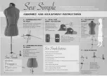
Sew Simple
Brand: Adjustoform Pages: 2
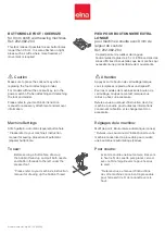
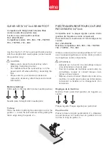
202-082-204
Brand: ELNA Pages: 2
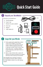
Skeinminder
Brand: Alpenglow Yarn Pages: 4
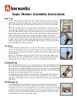
Super Skeiner
Brand: Akerworks Pages: 2
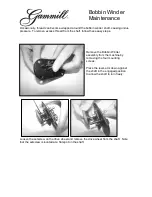
Bobbin Winder
Brand: Gammill Pages: 3
202-239-002
Brand: ELNA Pages: 2

ULTRAFEED 120931
Brand: Sailrite Pages: 24

MDK 60 Series
Brand: Racing Pages: 3
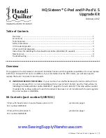
Sixteen C-Pod
Brand: handi quilter Pages: 11
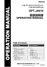
OPT-J0410
Brand: MIMAKI Pages: 5
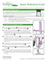
HQ Simply Sixteen
Brand: handi quilter Pages: 2
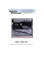
Quilter's Cruise Control Voyager 17
Brand: Hinterberg Design Pages: 3
H-TYPE CLASSIC
Brand: DURKOPP ADLER Pages: 18
4234DT
Brand: Brother Pages: 80


