background image

Y11-001 Jun.2012 <MEE>

TECHNICAL MANUAL FOR NORTH AMERICA

June.2012

Models

Lossnay  Unit

Lossnay  Remote Controller

PZ-60DR-E
PZ-41SLB-E
PZ-52SF-E

LGH-F300RX

5

-E

LGH-F470RX

5

-E

LGH-F600RX

5

-E

LGH-F1200RX

5

-E

Summary of Contents for Lossnay LGH-F1200RX5-E

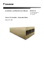
Page 1: ...TECHNICAL MANUAL FOR NORTH AMERICA June 2012 Models Lossnay Unit Lossnay Remote Controller PZ 60DR E PZ 41SLB E PZ 52SF E LGH F300RX5 E LGH F470RX5 E LGH F600RX5 E LGH F1200RX5 E ...

Page 2: ...Y11 001 Jun 2012 MEE ...

Page 3: ... Fire retardant property U 30 6 Lossnay Core Sound Reducing Properties Test U 31 7 Changes in the Lossnay Core U 32 8 Comparing Energy Recovery Techniques U 34 CHAPTER 4 Characteristics 1 How to Read the Characteristic Curves U 38 2 Calculating Static Pressure Loss U 38 3 How to Obtain Efficiency from Characteristic Curves U 41 4 Sound U 42 5 NC Curves U 48 CHAPTER 5 System Design Recommendations ...

Page 4: ...lection Efficiency for Each Lossnay Filter U 77 4 Comparing Dust Collection Efficiency Measurement Methods U 78 5 Calculating Dust Concentration Levels U 80 CHAPTER 9 Service Life and Maintenance 1 Service Life U 82 2 Cleaning the Lossnay Core and Pre filter U 82 CHAPTER 10 Ventilation Standards in Each Country 1 Ventilation Standards in Each Country U 86 2 United States of America U 87 3 United K...

Page 5: ...nally when CO2 sensor or other equipment is connected C 28 5 10 When switching By pass externally C 29 5 11 When using the remote local switching and the ON OFF input level signal C 29 5 12 When connecting to the City Multi Lossnay remote controller PZ 52SF E or Mitsubishi Electric Air Conditioner Network System MELANS C 30 6 Precautions When Designing M NET Systems 6 1 M NET Transmission Cable Po...

Page 6: ...ial operation C 76 12 Lossnay Remote Controller PZ 60DR E 12 1 Parts Names C 78 12 2 Setting the Day of the Week and Time C 79 12 3 Using the Remote Controller C 79 12 4 Care and Maintenance C 83 12 5 Servicing C 83 12 6 How to Install C 84 12 7 Test Run C 85 12 8 Function Selection C 86 13 Lossnay Remote Controller PZ 41SLB E C 91 14 Lossnay M NET Remote Controller PZ 52SF E C 92 15 Appendix 15 1...

Page 7: ......

Page 8: ...Lossnay Unit ...

Page 9: ......

Page 10: ...CHAPTER 1 Ventilation for Healthy Living ...

Page 11: ...2 or more as buildings Law maintenance and ventilation water supply discharge management according to the Environmental Sanitation Management Standards is obligatory The following table gives a specific account of buildings in Tokyo Tokyo Food and Environment Guidance Center Report Specific Account of Buildings in Tokyo March 2003 Note Excludes buildings with an expanded floor space of 32 300 to 5...

Page 12: ...of CO will increase rapidly due to incomplete combustion 18 Industrial Safety and Health Act Hypoxia prevention regulations 16 Normal concentration in exhaled air 16 12 Increase in pulse and breathing resulting in dizziness and headaches 15 Flame in combustion devices will extinguish 12 Short term threat to life 7 Fatal Concentration ppm Effect of Concentration Changes 0 01 0 2 Standard atmosphere...

Page 13: ...amination estimated when the physical and chemical properties of the air deteriorate in proportion to the increase of CO2 0 10 General tolerable concentration The Building Standard Law of Japan Law for Maintenance of Sanitation in Buildings 0 15 Tolerable concentration used for ventilation calculations 0 2 0 5 Relatively poor 0 5 or more Very poor 0 5 Long term safety limits U S Labor Sanitation A...

Page 14: ...tion Method Mainly used in small to medium sized buildings with areas being ventilated using ventilation air intake via independent ventilation devices The use of this method has recently increased as independent control is becoming more feasible Centralized Ventilation Method Independent Zoned Ventilation Method Air intake ventilation air Filters Air exhaust stale air Cassette type indoor units o...

Page 15: ...f ventilation is required even for a few occupants The user in each zone can operate the ventilator without restrictions The ventilator can be operated even during off peak hours Comfort An ideal supply air diffuser and return grille position can be selected as the supply air diffuser and return grille can be positioned without restrictions The only noise in the room is the sound of air movement A...

Page 16: ...be blown away The force that blows the paper away is called wind pressure and is normally expressed in inH2O Wind pressure is divided into the following three types 4 2 1 Static Pressure The force that effects the surroundings when the air is contained such as in an automobile tyre or rubber balloon For example in a water gun the hydraulic pressure increases when pressed by a piston If there is a ...

Page 17: ... D are obtained Finally the throttle device is completely opened and the auxiliary fan is operated until the static pressure in the chamber reaches 0 The maximum point of the air volume Point E the air volume at this point is called the fully opened air volume is obtained The points are connected as shown below and are expressed as air volume static pressure curves Q H curve Connection Wind disper...

Page 18: ...r occupant table below iO Ventilation air enthalpy Btu lb iR Indoor enthalpy Btu lb Floor Space per Occupant ft2 According to the Japan Federation of Architects and Building Engineers Associations Required Ventilation Air Intake Volume Per Occupant CFM per occupant Caution The amount of smoking that could be present in each type of room must be carefully considered when obtaining the required vent...

Page 19: ...entilation air enthalpy kJ kg iR Indoor enthalpy kJ kg Floor Space per Occupant m2 According to the Japan Federation of Architects and Building Engineers Associations Required Ventilation Air Intake Volume Per Occupant m3 h occupant Caution The amount of smoking that could be present in each type of room must be carefully considered when obtaining the required ventilation volume shown in the table...

Page 20: ... ft2 4 9 W ft2 SI unit When the load per floor area of 1 m2 with a ventilation volume of 25 m3 h occupant is calculated with the air conditions detailed above the following is obtained Ventilation air load 1 2 kg m3 Specific gravity of air 0 2 occupant m2 number of occupants per 1 m2 25 m3 h occupants ventilation air volume 31 8 kJ kg air enthalpy difference indoor outdoor 190 8 kJ h m2 53 0 W m2 ...

Page 21: ...ccupant in the office Sensible heat SH 63 0 W person W occupant Latent heat LH 69 0 W person W occupant Total heat TH 132 0 W person W occupant The heat generated per 1 ft2 m2 of floor space Heat generated from occupants 132 0 W person 132 0 W occupant 0 0186 person ft2 0 2 occupant m2 2 5W ft2 26 4 W m2 2 Heat generated from electrical equipment lighting The approximate value of the lighting and ...

Page 22: ...ulated with the air conditions detailed above the following is obtained Ventilation air load 0 749 Ib ft3 0 0186 occupants ft2 15 CFM occupant 14 4 Btu Ib 0 30 Btu min ft2 5 2 W ft2 SI unit When the load per 1 m2 of floor area with a ventilation volume of 25 m3 h occupant is calculated with the air conditions detailed above the following is obtained Ventilation air load 1 2 kg m3 0 2 occupants m2 ...

Page 23: ......

Page 24: ...CHAPTER 2 Lossnay Construction and Technology ...

Page 25: ...re Construction and Technology Simple Construction The Lossnay core is a cross air passage total energy recovery unit constructed from specially treated membrane with a corrugated structure The fresh air and exhaust air passages are totally separated allowing the fresh air to be introduced without mixing with the exhaust air Principle The Lossnay Core uses the heat transfer properties and moisture...

Page 26: ...m the high temperature to low temperature side 2 As shown in the diagram at right the energy recovery efficiency is affected by the resistance of the partition plate For Lossnay there is little difference when compared to materials such as copper or aluminium that also have high thermal conductivity Heat Resistance Coefficients t1 t2 Ra1 Ra2 Rp Partition plate Ra1 Ra2 Rp 2 Humidity Latent Heat Rec...

Page 27: ...nergy recovery efficiency is low if the exhaust volume is lower and high if the exhaust volume is higher SA Fresh air exhaust Fresh heating cooling air RA Stale air induction Dirty heating cooling air Indoors Outdoors EA Exhaust air Stale air OA Fresh air induction Fresh air Calculation of Supply Air Condition After Passing Through Lossnay If the Lossnay energy recovery efficiency and the conditio...

Page 28: ...ill balance at an equal state and the wet bulb temperature is obtained 3 Absolute Humidity x Ib Ib kg kg Weight Ib kg of the water vapor that corresponds to the weight Ib kg of the dry air in the humid air 4 Relative Humidity ϕ Ratio of the water vapor pressure Pw in the humid air and the water vapor pressure Pws in the saturated air at the same temperature Relative humidity is obtained with the f...

Page 29: ...ay Core can be calculated with the formula below Total heat recovered qT γ Q iOA iSA W γ Q iOA iRA ηi Where V e n t i l a t i o n l o a d L o s s n a y C o r e e n e r g y r e c o v e r y V e n t i l a t i o n l o a d L o s s n a y C o r e e n e r g y r e c o v e r y Outdoor air condition in winter Supply air condition of the Lossnay Supply air condition of the Lossnay Room air condition in summer...

Page 30: ...CHAPTER 3 General Technical Considerations ...

Page 31: ... 530 3 100 14 Conventional Ventilator Unit If a conventional ventilator unit is used the energy recovered will be 0 as the supply air diffuser is equal to the outdoor air The ventilation load is 36 4 22 7 0 0749 600 620 2 Btu min 10 9 kW Calculation Example Summer Conditions Supply air Room air Indoor Unit of Air Conditioner Lossnay Unit Sensible HRV Unit Conventional Ventilator Unit Dry bulb temp...

Page 32: ...0749 600 391 0 Btu min 6 9 kW Calculated enthalpy recovery efficiency 265 1 265 1 391 0 100 40 Conventional Ventilator Unit If a conventional ventilator is used the supply air diffuser is the same as the outdoor air and the exhaust is the same as the room air Thus the energy recovered is 0 kcal and the Ventilation load is 16 6 2 1 0 0749 600 651 6 Btu min 11 5 kW Calculation Example Winter Conditi...

Page 33: ...lpy enthalpy recovery efficiency outdoor air enthalpy Outdoor air enthalpy outdoor air enthalpy indoor enthalpy enthalpy recovery efficiency Data obtained from above equation and psychrometric chart Dry bulb temperature Wet bulb temperature Relative humidity Absolute humidity Enthalpy F C F C Ib Ib kg kg Btu Ib kg kg Dry bulb temperature Wet bulb temperature Relative humidity Absolute humidity Ent...

Page 34: ...lume indoor enthalpy indoor blow enthalpy Ventilation load q1 1 enthalpy recovery efficiency or Air specific gravity ventilation volume indoor blow enthalpy indoor enthalpy Energy recovery q3 q1 q2 or Ventilation load q1 enthalpy recovery efficiency q1 q2 or Ventilation load q1 enthalpy recovery efficiency Ventilation load Ventilation load W Ventilation load with Lossnay W Energy recovered W Venti...

Page 35: ...U 26 CHAPTER 3 General Technical Considerations 3 Psychrometric Chart 3 1 US unit AEX 120 99 page 2 Figure 2 A psychrometric chart ...

Page 36: ... 0 5 0 4 5 4 0 3 5 1 1 1 0 9 8 7 6 4 5 3 2 1 0 1 2 4 5 5 0 5 1 0 9 0 8 0 7 0 6 0 5 0 4 0 3 0 2 5 6 0 5 5 6 5 7 0 7 5 8 0 8 5 9 5 9 0 8 5 8 0 7 5 7 0 6 5 6 0 5 5 5 0 5 0 4 5 4 0 4 0 4 5 3 5 3 0 2 5 2 0 1 5 1 0 5 3 5 3 0 2 5 2 0 1 5 2 0 10 5 1 5 1 5 2 5 3 0 2 0 8 1 0 5 0 1 5 2 0 2 5 3 0 1 2 1 3 1 4 1 5 1 6 1 7 40000 40000 200 00 150 00 10 00 0 7 0 0 0 6 0 0 0 5 0 0 0 4 5 0 0 4 2 0 0 4 0 0 0 3 8 0 0 ...

Page 37: ... outlet ducts so that the openings are directly against the air flow and then connected to the impingers outside the ducts The impingers are filled with 100 mL physiological salt solution The airborne bacteria in the duct air are sampled at the rate of 10L air minute for three minutes 5 Test Bacteria The bacteria used in this test are as followed Bacillus subtilis IFO 3134 Pseudomonas diminuta IFO...

Page 38: ...r filtered by the HEPA filter and Location D on the inlet side Because the number of bacteria in Location A is substantially equal to one in Location B it is estimated that only a few bacteria are present in the Lossnay Core on the outlet side Also no test bacteria are detected at Location D The conclusion is therefore that the bacteria present in the outlet side will not pass through the inlet si...

Page 39: ...as also tested at General Building Research Corporation of Japan according to the fire retardancy test methods of thin materials for construction as set forth by JIS A 1322 The material was evaluated as a Class 2 flame retardant 5 Lossnay Core Fire retardant property ...

Page 40: ...ir Energy Recovery Ventilator May 18 2001 W1231 H398 D1521 ANNEXED DRAWINGS No 1 2 show details Test Specimen Test Results Test method was determined according to JIS A 1416 1994 Method for laboratory measurement of sound transmission loss and Architectural Institute of Japan Standard Measurement method on sound transmission loss of small building elements Notes 1 The graph shows level difference ...

Page 41: ...ment 1 Air Handling Method 4 fan coil units perimeter zone per floor Chilling Unit Absorption type 250 kT 1 unit turbo 250 kT 2 units Gas Direct Heating Cooling Boiler 340 kT heating 1 630 kW 2 Ventilation Method Air air total energy recovery unit Lossnay LS 200 18 units installed in penthouse Outdoor air treatment volume 27 211 CFM 46 231 CMH Exhaust air treatment volume 31 980 CFM 54 335 CMH 3 L...

Page 42: ... CFM 200 m3 hr of that value 0 70 80 90 300 180 100 0 40 200 0 80 300 1 20 500 300 700 420 CMH CFM 7 5 Conclusion 1 Changes in the the Lossnay Core after approximately 11 years of use and an estimated 28 000 operation hours were not found The static pressure loss was 0 60 to 0 64 in H2O at 300 CFM 150 to 160 Pa at 500 m3 hr which was a 0 04 in H2O 10 Pa increase The exchange efficiencies had decre...

Page 43: ...re and high humidity ventilation air passes through the rotor with the heat and humidity being absorbed by the rotor When the rotor rotates it moves into the exhaust air passage and the heat and humidity is discharged to the outdoors because the exhaust is cool and has low humidity The rotor rotates and returns to the ventilation air passage to absorb the heat and humidity again Function of the pu...

Page 44: ...oss air volume approx 10 on the exhaust side with the fan position to the core Gas transmission Ammonia approx 2 9 In certified EATR on AHRI Mitsubishi core EATR is 0 Wheel types EATR are 0 04 7 7 Purged air volume occurs To prevent exhaust leaking to the air intake side a purge air volume 6 to 14 leak is created on the exhaust side Thus there are problems in the purge sector operation conditions ...

Page 45: ......

Page 46: ...U 37 CHAPTER 4 Characteristics CHAPTER 4 Characteristics ...

Page 47: ... distribution If the static pressure increases the air volume will decrease The air volume static pressure curve Q H curve example shows the percentage at the decrease A static pressure of 0 08 in H2O 19 6 Pa is applied to Point A and the air volume is 300 CFM 500 m3 h The duct resistivity curve shows how the static pressure is applied when a duct is connected to the Lossnay Thus the L 32 7 ft 9 9...

Page 48: ... kg m3 v Velocity m s 180 160 140 120 100 80 60 40 20 2 4 6 8 101214 16 18 Outdoor air pressure Pa Velocity m s Reference Pressure loss caused by outdoor air wind velocity inH2O 0 003019 r V2 r Air weight 0 0749 Ib ft3 v Velocity ft s 0 0 1 0 2 0 3 0 4 0 5 0 6 0 7 0 10 20 30 40 50 60 Outdoor air ft s Outdoor air pressure loss inH 2 O ...

Page 49: ...ion 9 45 Smooth Elbow With or without vanes rectangular or round 1 2 times value for similar 90 10 Expansion a 5 10 20 30 40 Loss is for hV1 hV2 0 17 0 28 0 45 0 59 0 73 10D 17D 27D 36D 43D 11 Contraction a 30 45 60 Loss is for V2 0 02 0 04 0 07 1D 2D 4D No Duct Area Outline Diagram Conditions C Value Length of Equivalent Round Pipe 12 Transformer 0 15 9D 13 Short Entrance 0 50 30D 14 Short Exit 1...

Page 50: ...1 0 1 1 1 4 1 2 1 3 80 70 60 50 40 Efficiency obtained from supply side air volume Energy recovery efficiency Air volume ratio Exhaust air volume Supply air volume Corrected energy recovery efficiency Recovery efficiency Static pressure outside unit Temperature recovery efficiency Enthalpy recovery efficiency heating Enthalpy recovery efficiency cooling Static pressure loss related parts straight ...

Page 51: ...re called units of phons for example the point on the 60 curve is perceived as 60 phons On average the human detects sounds that are less than 1 000 Hz as rather weak and sounds between 2 000 to 5 000 Hz as strong 4 2 How to Measure Sound Levels A sound level meter JIS C 1502 IEC 651 is used to measure sound levels and has three characteristics A 1 C 2 and Flat as shown on the right These represen...

Page 52: ...and loud frequency These sounds are low during product design stages but sounds may become very disturbing if resonating on ceilings walls etc Example Continuous Frequency Analysis NC Curve Tolerable Sound Levels and NC Values According to Room Application Frequency band Hz Level dB Frequency Hz SPL dB Min audible limit Room Application dB NC Value Room Application dB NC Value Broadcasting studio ...

Page 53: ...u is overhead tracks not possible 80 Conversation is not Train passing through possible unless voice is shopping district raised 70 Voice is raised Shopping district with intentionally to converse heavy traffic 60 Loud but normal In busy office conversation is possible 50 Sound is audible and Among quiet group disturbing of pedestrians 40 Quiet but not peaceful In quiet group of people 30 Peaceful...

Page 54: ...iling embedded type Lossnay unit and supply air diffuser with return grille is the direct sound from the supply air diffuser return grille and is the echo sound to is the direct sound emitted from the unit and duct that can be detected through the finished ceiling is the echo sound of 3 Position of Sound Source and Sound Value SPL dB PWL 10 log II i ii SPL Sound pressure level at reception point d...

Page 55: ...unit using the following specifications if disturbing sound could be emitted from large units Refer to Fig 4 a Decrease in diameters in the ductwork Ex 10 dia ø 250 6 dia ø 150 8 dia ø 200 4 dia ø 100 b Curves in aluminum flexible ducts etc Especially if immediately installed after unit outlet c Opening in ceiling panels d Hanging the unit on materials that cannot support the wight B The following...

Page 56: ...with a small diameter is more effective 3 When supply air diffuser and return grille is the source of the sound Part 2 A If the main unit and supply air diffuser and return grille are integrated as shown in Fig 8 or if the measures taken in 2 A and B are inadequate add soundproofing material that has a high sound absorbency as shown in Fig 8 a This is not however very effective with direct sounds ...

Page 57: ...8 V 60 Hz Power supply 230 V 60 Hz 10 15 20 25 30 35 40 45 50 55 60 65 70 75 80 85 90 Overall 62 5 125 250 500 1K 2K 4K 8K Octave band frequency near center Hz Octave band sound pressure level dB 1 5 m below Measurement point NC 10 NC 20 NC 30 NC 40 NC 50 NC 60 Extra high High Low Extra Low NC 70 10 15 20 25 30 35 40 45 50 55 60 65 70 75 80 85 90 Overall 62 5 125 250 500 1K 2K 4K 8K Octave band fr...

Page 58: ...e 25 dB or less A range Background noise 25 dB or less A range Measurement site Anechoic chamber Measurement site Anechoic chamber Operation conditions Lossnay ventilation Operation conditions Lossnay ventilation Power supply 208 V 60 Hz Power supply 230 V 60 Hz 10 15 20 25 30 35 40 45 50 55 60 65 70 75 80 85 90 Overall 62 5 125 250 500 1K 2K 4K 8K Octave band frequency near center Hz Octave band ...

Page 59: ......

Page 60: ...CHAPTER 5 System Design Recommendations ...

Page 61: ...snay units should not be used in these types of applications 1 4 Other Special Conditions A A C C B S a t u r a t i o n c u r v e Dry bulb temperature F C Absolute humidity kg kg Lossnay units cannot be installed in locations where toxic gases and corrosive elements such as acids alkalis organic solvents oil mist or paints exist Cannot be installed where heat is recovered from odiferous air and su...

Page 62: ... water from going into the system Do not use standard vent caps or round hoods where those may come into direct contact with rain water A deep hood is recommended 5 Bypass Ventilation Do not operate bypass ventilation when heating during winter Frost or condensation may form on the main unit 6 Night purge function Do not use the night purge function if fog or heavy rain is expected Rain water may ...

Page 63: ... Nitric acid HNO3 Mist Toxic 180 180 10 Phosphoric acid H3PO4 Mist Toxic 41 41 0 1 Acetic acid CH3COOH Mist Bad odor 2 115 2 115 25 Hydrogen chloride HCl Gas Toxic 427 58 427 58 5 Hydrogen fluoride HF Gas Toxic 90 90 0 6 Sulfur dioxide SO2 Gas Toxic 32 8 32 8 0 25 Hydrogen sulfide H2S Gas Toxic 2 3 2 3 10 Ammonia NH3 Gas Bad odor 635 40 635 40 50 Phosphine PH3 Gas Toxic 0 26 0 26 0 1 Methanol CH3O...

Page 64: ...ing Using Outdoor Air During cooler seasons such as between spring and summer or between summer and fall if the occupants in a room cause the temperature of the room to rise bypass ventilation will draw in the cool outside air and use it as is to cool the room 3 Night Purge Bypass ventilation can be used to release hot air from inside the building that has accumulated during the hot summer season ...

Page 65: ...llation for Lossnay 10 1 Top bottom Reverse Installation All LGH RX5 models can be installed in top bottom reverse 10 2 Vertical and Slanted Installation All LGH RX5 models should not be used in both vertical and slanted installation to avoid any problems motor noise water incoming etc ...

Page 66: ...ation avoid undue stress on the fan motors Referring to the diagrams below Lossnay with extra fans should be used at the point of left side from A Q H for Lossnay Without Extra Fan Q H for Lossnay With Extra Fan Static pressure generating component Additional fan EA OA Lossnay Lossnay fan SA RA H H1 H H1 H2 H1 H2 Q1 Q1 Q1 Lossnay with static pressure increasing component Lossnay with static pressu...

Page 67: ......

Page 68: ...CHAPTER 6 Examples of Lossnay Applications ...

Page 69: ...by conference room 2nd to 7th floor Offices salons board room Air conditioning system Package air conditioning Ventilation Ceiling embedded type Lossnay straight centrifugal fan 1 2 System Requirements 1 Operation system that answers individual needs was required Free independent operation system Simple control 2 Effective use of floor space Eliminating the equipment room 3 Application to Building...

Page 70: ...of the ceiling The supply air would be discharged into the ceiling where after mixing with the return air from the air conditioner it was supplied to the air conditioner The air in the toilet kitchenette and elevator hall etc would be exhausted with a straight centrifugal fan The OA supply would use the air supplied from the Lossnay unit The OA volume would be obtained by setting the Lossnay suppl...

Page 71: ...or units of air conditioner system layout Lossnay Air cooling heat pump air conditioner Air cooling heat pump air conditioner Additional room Additional room Women s dressing room Additional rooms Machine room Office machine room Men s dressing room Kitchenette Machine room Kitchenette Men s dressing room Office machine room Women s dressing room Additional rooms Machine room Office Office ...

Page 72: ... added to the air conditioning system to allow adequate humidification Installing of a filter on each air circulation system in the room was effective for dust removal but if the outdoor air inlet was near a source of dust such as a road a filter should also be installed on the ventilation system 1 4 Outcome 1 Air conditioning and ventilation needs were met on an individual room or were basis 2 Op...

Page 73: ...portant and because the building was surrounded by other buildings the intake and exhaust ports must be placed as far apart as possible 2 Small Scale Urban Building 2 1 System Design Challenges The system was designed effectively using limited available air conditioner and ventilator installation space For this application air flow must be considered for the entire floor and the ventilator was ins...

Page 74: ...e and the air conditioned room was ventilated with ceiling embedded type Lossnay units The toilet and kitchenette etc were ventilated with a straight centrifugal fan System Design Building specification RC Reinforced Concrete Total floor space 10 000 ft2 931 m2 GF to 3F Application per floor GF Waiting room diagnosis rooms surgery theater director room kitchen 2F Patient rooms nurse station rehabi...

Page 75: ...f air conditioner after the air flow was reduced Kitchen Exhaust with negative pressure ventilation fan or straight centrifugal fan Outdoor air was supplied with the straight centrifugal fan Machine room Exhaust with positive pressure ventilation fan 3 4 Outcome 1 The following outcomes were possible by independently ventilating the air conditioned rooms with Lossnay units Disease transmission cou...

Page 76: ...of overall comfort saving space and energy an air conditioning and ventilation system with a ceiling embedded type fan coil unit and ceiling embedded type Lossnay was installed 2 Automatic operation using a weekly program timer was used operating when the general classrooms and special classrooms were used 3 By using a ventilation system with a total energy recovery unit energy was saved and sound...

Page 77: ...increased and the CO2 concentration reached a set level for example 1 000 ppm in the Building Management Law a separate centrifugal fan turned on automatically The system could also be operated manually to rapidly remove smoke and odors B Convention and banquet halls The system included several outdoor air introduction type package air conditioners and straight centrifugal fans for ventilation How...

Page 78: ...ecial knowledge was required for operation and there were problems in response to the users needs 2 When the centralized method was used the air even in rooms that were not being used was conditioned increasing operation costs 3 Machine room space was necessary 4 Duct space was necessary 6 3 Details 1 Air conditioning Facilities 1 Small rooms Air cooling heat pump chiller and fan coil unit combina...

Page 79: ......

Page 80: ...CHAPTER 7 Installation Considerations ...

Page 81: ...air Duct incline Over 1 30 toward the wall to prevent entry of rainwater Air supply grille user supplied user supplied Air supply grille Air supply grille 18 24 Inspection port user supplied user supplied A OA Outside air EA Exhaust air OA Outside air EA Exhaust air 16 5 16 16 5 16 Suspension bolt position Suspension bolt position Suspension bolt position Exhaust air grille B Supply air grille 23 ...

Page 82: ...ype A MELANS centralized controller can also be used 1 3 Installation Applications 1 Installing Two Units to One Outside Air Duct The main unit s supply outlet and suction inlet and the room side and outdoor side positions cannot be changed However the unit can be installed upside down and installed as shown below This is applicable when installing two units in one classroom etc 2 System Operation...

Page 83: ......

Page 84: ...CHAPTER 8 Filters ...

Page 85: ...by JIS Z 8901 for performance test particles are employed 3 Dust generated in rooms where there is no smoking has approximately the same diameter as outdoor air 4 Smoking in general offices Japan Percentage of smokers Approx 70 adult men Average number of cigarettes Approx 1 person h including non smokers Length of cigarette tobacco section Approx 1 6 inch 4 cm Amount of dust generated by one ciga...

Page 86: ...ommercial Lossnay LGH 82 8 12 Protection of heat recovery element Tested dust Measurement method Filter type Effectiveness of the filters used in the Lossnay units are shown below expressed in terms of collection ratio 20 40 60 80 100 Collection ratio Colourimetric method 90 filter NP 400 Particle diameter mil 7 9 10 3 1 2 10 2 1 6 10 2 2 4 10 2 3 1 10 2 3 9 10 2 7 9 10 2 1 1 10 1 1 6 10 1 2 4 10 ...

Page 87: ...tational method Synthetic Regulated air cleaner fine particles 72 Morocco Black 23 Cotton linter 5 Dust weight measured beforehand Filter passage air volume measured Weigh the dust remaining on the filter and compare Gravitational ratio Pre filter Filter for air conditioning for coarse dust ASHRAE Colorimetric method Atmospheric dust Degree of contamination of white filter paper Degree of contamin...

Page 88: ...s the same and the results are determined by the sampled air volume ratios on both sides Dust collection ratio Out flow side sampling amount In flow side sampling amount 100 Out flow side sampling amount Orifice Dust supply device Manometer Motor Dust container Mixing blades Dust supply outlet Unit inch mm Rectifying grid Air volume adjustment plate Air feed fan Window Specimen Performance test de...

Page 89: ...system using Lossnay units is shown below Dust concentration levels can be easily determined using this diagram Dust Concentration Study Diagram Qo Outdoor air intake amount CFM m3 h Qi Indoor unit of air conditioner air volume Total air volume of indoor unit CFM m3 h ηo Filtering efficiency of humidifier with high efficiency filter colorimetric method ηi Efficiency of the filter for the indoor un...

Page 90: ...CHAPTER 9 Service Life and Maintenance ...

Page 91: ...NG are indicated on the remote controller Clean the Lossnay cores once two year Clean the Lossnay cores once a year If possible Frequency should be increased depending on the extent of dirt Models LGH F300 to F600RX5 Models LGH F1200RX5 Hinge Hinge bracket Maintenance cover Maintenance cover Hinge Lossnay core Handle Handle Lossnay core Main unit Hinge bracket Air filter Main unit Air filter 3 Air...

Page 92: ...Lossnay unit Note If FILTER and CLEANING are indicated on the remote controller turn off the indication after maintenance CAUTION Never wash the filters in very hot water and never wash them by rubbing them Do not dry the filters by exposing them to a flame 2 Lossnay cores Use a vacuum cleaner to suck up the dust and dirt on the exposed surfaces of the Lossnay cores Use a soft brush only to clean ...

Page 93: ......

Page 94: ...CHAPTER 10 Ventilation Standards in Each Country ...

Page 95: ...ement system ventilation capacity and characteristics Effective ventilation capacity V 20Af N m3 Af Floor space m2 N Floor space occupied by one person Impurity Volume of Particles Less than 0 15 mg per 1 m3 of air CO Rate Less than 10 ppm CO2 Rate Less than 1 000 ppm Temperature 1 Between 17 C and 28 C 2 When making the room temperature cooler than the outside temperature do not make the differen...

Page 96: ... Computer lab 10 5 0 12 0 6 25 15 7 4 1 Media center 10 5 0 12 0 6 A 25 15 7 4 1 Music theater dance 10 5 0 06 0 3 35 12 5 9 1 Multi use assembly 7 5 3 8 0 06 0 3 100 8 4 1 1 Food and beverage Service Restaurant dining rooms 7 5 3 8 0 18 0 9 70 10 5 1 2 Cafeteria fast bood dining 7 5 3 8 0 18 0 9 100 9 4 7 2 Bars cocktail lounges 7 5 3 8 0 18 0 9 100 9 4 7 2 Kitchen cooking 7 5 3 8 0 12 0 6 20 14 ...

Page 97: ... 8 0 18 0 9 120 9 4 6 1 Game arcades 7 5 3 8 0 18 0 9 20 17 8 3 1 Stages studios 10 5 0 06 0 3 D 70 11 5 4 1 GENERAL NOTES FOR TABLE 6 1 1 Related requirements The rates in this table are based on all other applicable requirements of this standard being met 2 Environmental Tobacco Smoke This table applies to ETS free areas Refer to Section 5 17 for requirements for buildings containing ETS areas a...

Page 98: ...on 1 7 l s m2 Heavy Laboratories 12 l s person 8 l s person Some Offices private 12 l s person 8 l s person 1 3 l s m2 Heavy Residences average 12 l s person 8 l s person Heavy Restaurant cafeteria 12 l s person 8 l s person Heavy Cocktail bars 18 l s person 12 l s person Heavy Conference rooms average 18 l s person 12 l s person Some Residence 18 l s person 12 l s person Heavy Restaurant 18 l s p...

Page 99: ......

Page 100: ...CHAPTER 11 Lossnay Q and A ...

Page 101: ...imilar to the phenomenon during heating in winter where the window pane is wet but the paper blinds are dry humidity is transferred through the plate 4 When is the forced simultaneous air intake exhaust type more efficient When a building is sealed and normal ventilation is used accurate exhaust is not possible unless a suction inlet is created Forced simultaneous air intake exhoust is possible be...

Page 102: ...nded cassette type air conditioner PLZ J140KA9G9 One unit With Lossnay PLZ J112KA9G9 One unit Operation time Cooling 10 hours day 26 days month 4 months year operation ratio 0 7 Heating 10 hours day 26 days month 5 months year operation ratio 0 7 Power costs Tokyo Power special industrial power 6 kV supply Summer 16 15 yen kWh Other 14 65 kWh There are also savings in maintenance costs ventilation...

Page 103: ...but for both suction or both forced the rate is 2 to 3 LGH type fan position is both forced For using LU type if the difference in static pressure between SA and RA and EA and OA is 2 0 inH2O the air leakage rate will be 2 5 and 3 4 respectively This value is not a problem for actual use However the single suction or single forced methods will have a leakage rate of 10 or higher and should be avoi...

Page 104: ...e exhaust air outlet The Lossnay unit uses the forced simultaneous supply exhaust method so insufficient ventilation found in standard ventilators without air intake is found Caution 1 The fresh outdoor air supplied to the room should not short circulate and be drawn back into the return grille should flow through the entire room 2 The relation of the supply and suction air flows must be also cons...

Page 105: ...e false ceiling so an inspection hole is required to access the Core and filter section and for fan maintenance Refer to the installation manual for details 18 What must be performed during maintenance Periodic inspection and cleaning of the Lossnay Core and air filter is necessary Refer to Chapter 9 Service Life and Maintenance for details 19 Can the Lossnay be used in factories Do not install in...

Reviews: