background image

WORKSHOP MANUAL

EVOLUTION-VII

Pub. No. S0105CT9A

Summary of Contents for Lancer Evolution-VII

Page 1: ...WORKSHOP MANUAL EVOLUTION VII Pub No S0105CT9A ...

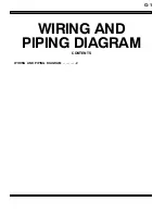
Page 2: ...G 1 WIRING AND PIPING DIAGRAM CONTENTS WIRING AND PIPING DIAGRAM 2 ...

Page 3: ...e antennas are routed in some parts of closed section structures of the body construction These pole antennas must be removed before body panels in these areas can be replaced 1 1 Pole antenna Vehicles with pole antennas A Antenna feeder line Vehicles with pole antennas A RJAK104003 378 ...

Page 4: ...F 1 BODY COLOUR CONTENTS BODY COLOUR CODE 2 BODY COLOUR CHARTS 2 NEW COLOUR NUMBERS 3 BODY COLOURING 3 BUMPER 3 BLACK PAINT 3 ...

Page 5: ...nt supplier from which the colour be purchased Colour Body colour d Colour number Body colour name Composition of film Engine compartment and luggage compartment colour code Colour number Colour name SILVER A69 AC11169 Satellite Silver Metallic AC10595 GRAY BRIGHT BLUE T10 CMT10010 French Blue Solid CMB17004 BRIGHT BLUE BLACK X42 AC11342 Amethyst Black Interference Pearl AC10903 BLACK WHITE W83 AC...

Page 6: ...ring Center 3 System colour code W N White H A U Silver Gray X J Black R P Red Y C S E M K Brown Yellow including Orange Maroon and Gold G F L Green Olive B T D Blue V Purple Codes within the parenthesis can be also used 4 Colour classification code From 10 to 16 The body colour is indicated 17 The body inner panel colour is indicated 5 Specific number Serial number numbering management BODY COLOU...

Page 7: ...BODY COLOUR Body Colouring F 4 BLACK PAINT Headlamp support Black AC10657 Door sash Rear door Front door Black AC10790 Wheel house Black AC10657 ...

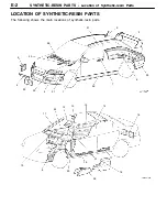
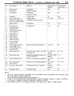
Page 8: ...E 1 SYNTHETIC RESIN PARTS CONTENTS LOCATION OF SYNTHETIC RESIN PARTS 2 ...

Page 9: ...ocation of Synthetic resin Parts E 2 LOCATION OF SYNTHETIC RESIN PARTS The following shows the main locations of synthetic resin parts 1 1 17 27 28 25 29 7 18 23 19 24 16 9 22 2 26 10 1 21 5 14 13 15 12 11 20 4 6 8 3 30 31 24 ...

Page 10: ...plate garnish Front door trim Rubber denatured polypropylene PP E P 80 25 Rear bumper face With talc added rubber denatured polypropylene PP E P TD HMPP 80 100 26 Side sill extension With 20 talc added rubber dena tured polypropylene PP E P TD20 HMPP 110 27 Center pillar trim lower With 10 talc added polypropylene PP TD10 PPF 110 120 28 29 Front deck garnish Floor console With 20 talc added polypr...

Page 11: ...NOTES ...

Page 12: ...D 1 CORROSION PROTECTION CONTENTS BODY SEALING LOCATIONS 2 FLOOR 2 UPPER BODY 2 SIDE BODY 2 UNDERCOAT APPLICATION LOCATIONS 5 ...

Page 13: ...faces such as the drip rails pillars or clinch and where the appearance of the paint surface is important apply sealant or wipe away sealant after application to make the amount of sealant even Be careful not to cover the drain hole bold dotted line indicates the application location at the back FLOOR 2 1 3 4 UPPER BODY 2 2 2 6 5 7 SIDE BODY 11 12 9 8 10 ...

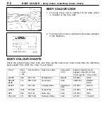
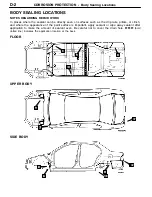
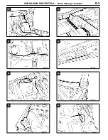
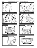
Page 14: ...CORROSION PROTECTION Body Sealing Locations 1 2 3 4 5 6 7 8 D 3 ...

Page 15: ...CORROSION PROTECTION Body Sealing Locations 9 10 11 12 Hood Front door Rear door Trunk lid D 4 ...

Page 16: ... resistance to rust corrosion chipping and vibration an undercoat is applied to certain areas of the underbody After completing body repairs restore this undercoat if necessary Mark the areas indicated with asterisks to make sure no undercoat adheres to these areas Undercoat Film thickness of at least 0 5 mm ...

Page 17: ...NOTES ...

Page 18: ...LACEMENT CONTENTS HEADLAMP SUPPORT 3 FENDER SHIELD 4 FRONT PILLAR 7 CENTER PILLAR 9 SIDE SILL 12 QUARTER OUTER 14 ROOF 17 REAR END PANEL 18 REAR FLOOR 19 QUARTER INNER 21 FRONT DOOR OUTER PANEL 23 REAR DOOR OUTER PANEL 24 ...

Page 19: ...C 2 NOTES ...

Page 20: ...pot welding MIG plug welding J indicates two panels to be welded Y indicates three panels to be welded MIG spot welding MIG arc welding continuous Braze welding Anti corrosion agent application locations Use access holes to apply liberally to butt welded joints A A B B B REPAIR WELDS Right side ...

Page 21: ...tes two panels to be welded Y indicates three panels to be welded MIG spot welding MIG arc welding continuous Braze welding Anti corrosion agent application locations Use access holes to apply liberally to butt welded joints A A F REPAIR WELDS NOTE For the weld points for the headlamp support refer to P C 3 Headlamp Support ...

Page 22: ...WELDED PANEL REPLACEMENT Fender Shield C 5 C D B C B E D With the upper frame extension outer removed ...

Page 23: ...WELDED PANEL REPLACEMENT Fender Shield C 6 G H I F E G H 17 points left side only 4 points left side only RHD Right side RHD LHD H 5 points left side only ...

Page 24: ... MIG spot welding MIG arc welding continuous Braze welding Anti corrosion agent application locations Use access holes to apply liberally to butt welded joints 2point passenger s side B C B C 180 20 mm 60 10 mm A A D D REPAIR WELDS Foam acoustic material With the upper frame extension outer removed RS II Caution Do not use heat at areas using foam material as the foam material may burn ...

Page 25: ...ont pillar outer install a front pillar silencer protector filling up the gap with butyl tape RS II and then apply body sealant and structural adhesive on the area shown in the illustration Body sealant Adhesive Adhesive Type BRAND Epoxyayresin adhesive 3M DP 460 3M DP 420 or equivalent The following service procedures are only applied to RS II 4 After attaching the front pillar outer seal the hol...

Page 26: ...ates three panels to be welded MIG spot welding MIG arc welding continuous Braze welding Anti corrosion agent application locations Use access holes to apply liberally to butt welded joints 125 10 mm 290 10 mm 125 10 mm A B C D D B A C Foam acoustic material REPAIR WELDS RS II Caution Do not use heat at areas using foam material as the foam material may burn ...

Page 27: ... side sill outer reinforcement center side sill bulkhead and side sill reinforcement support from the new center pillar 2 To ensure the strength of the cut area of the front pillar cut the side outer panel 30 mm above the cut area Cut the new center pillar at the same positions 3 To prevent damage of the center pillar seatbelt reinforcement align the new center pillar reinforcement only to the bod...

Page 28: ...ith butyl tape 6 After attaching the center pillar outer seal the holes and flanges with bolts and plate tape fill the foam material through the holes as shown in the illustration Foam material Type Brand Used Foam acoustic material Two part ex panded urethane 3M ULTRAPRO Panel foam Yellow 7 About two hours after filling the foam material remove the bolts and plate tape and solder the sealed holes...

Page 29: ...es three panels to be welded MIG spot welding MIG arc welding continuous Braze welding Anti corrosion agent application locations Use access holes to apply liberally to butt welded joints 290 mm A B C D E A B C D F E 70 mm 70 mm F REPAIR WELDS Foam acoustic material RS II Caution Do not use heat at areas using foam material as the foam material may burn ...

Page 30: ...cement apply adhesive to the areas indicated in the illustration Adhesive Adhe sive Type BRAND sive Epoxyayresin adhesive 3M DP 460 3M DP 420 or equivalent 3 When attaching the side outer panel apply body sealant to the areas indicated in the illustration Body sealant Reference Depending on the damaged range it is advisable to replace the side outer panel and side sill outer reinforcement parts Cu...

Page 31: ... to be welded MIG spot welding MIG arc welding continuous Braze welding Anti corrosion agent application locations Use access holes to apply liberally to butt welded joints B D C A B 160 50mm A E 500 50 mm C REPAIR WELDS Foam acoustic material RS II Foam acoustic material 3 pointsLeft side RS II Caution Do not use heat at areas using foam material as the foam material may burn ...

Page 32: ...REPAIR WORK INSTALLATION 1 When attaching the quarter outer apply sealant to the areas indicated in the illustration For RS II attach the rear pillar silencer protector and fill the gaps with butly tape Body sealant Rear pillar silencer protector Left side only ...

Page 33: ...le shown in the illustration Foam material Type Brand Used Foam acoustic material Two part expanded wretane 3M ULTRAPRO Panel foam Yellow 3 After two hours after filling the foam material remove the bolts and plate tape and solder the sealed holes until a clip etc can be inserted completely Reference Parts replacement is advised depending on the damaged range Cuttable range Caution Avoid the fuel ...

Page 34: ...tes two panels to be welded Y indicates three panels to be welded MIG spot welding MIG arc welding continuous Braze welding Anti corrosion agent application locations Use access holes to apply liberally to butt welded joints REPAIR WELDS A C C A B B D D Adhesive Adhesive Type Chloroprene base drying sealant ...

Page 35: ...ription Spot welding MIG plug welding J indicates two panels to be welded Y indicates three panels to be welded MIG spot welding MIG arc welding continuous Braze welding Anti corrosion agent application locations Use access holes to apply liberally to butt welded joints REPAIR WELDS ...

Page 36: ... welding MIG plug welding J indicates two panels to be welded Y indicates three panels to be welded MIG spot welding MIG arc welding continuous Braze welding Anti corrosion agent application locations Use access holes to apply liberally to butt welded joints A D C B A B E F REPAIR WELDS ...

Page 37: ...ith the rear end panel refer to REAR END PANEL on P C 18 NOTE ON REPAIR WORK REMOVAL 1 Cut the rear floor panel 320 10 mm from the back of the rear seat back reinforcement Cut the rear floor pan 200 50 mm from the back of the rear seat back reinforcement as shown in the illustration Rear seat back reinforcement 200 50 mm ...

Page 38: ... to be welded MIG spot welding MIG arc welding continuous Braze welding Anti corrosion agent application locations Use access holes to apply liberally to butt welded joints A B C A B D E G H F I Vehicles with ACD REPAIR WELDS 9 points on left side With the quarter outer removed 6 points on right side Right side only NOTE For the weld points to the quarter outer refer to P C 14 ...

Page 39: ...WELDED PANEL REPLACEMENT Quarter Inner C 22 C E D F G H I Left side Vehicles with ACD With the side sill outer reinforcement rear removed ...

Page 40: ...es three panels to be welded MIG spot welding MIG arc welding continuous Braze welding Anti corrosion agent application locations Use access holes to apply liberally to butt welded joints REPAIR WELDS A B B 50 mm C C A Adhesive Adhesive Type Chloroprene base drying sealant NOTE After hemming the door outer panel MIG spot weld the flange overlap section at a pitch of approx 50 mm ...

Page 41: ...es three panels to be welded MIG spot welding MIG arc welding continuous Braze welding Anti corrosion agent application locations Use access holes to apply liberally to butt welded joints A B B C C A REPAIR WELDS 50 mm Adhesive Adhesive Type Chloroprene base drying sealant NOTE After hemming the rear door outer panel MIG spot weld the flange overlap section at a pitch of 50 mm ...

Page 42: ...ENSIONS AND MEASUREMENT METHODS 2 TYPE A PROJECTED DIMENSIONS 4 UNDER BODY 4 INSTALLATION OF SUSPENSION 6 TYPE B ACTUAL MEASUREMENT DIMENSIONS 8 UNDER BODY 8 INSTALLATION OF SUSPENSION 10 FRONT BODY 12 SIDE BODY 14 REAR BODY 15 INTERIOR 16 ...

Page 43: ...e probes the same A A D Do not bend or twist the measuring tape 3 Insert the tracking gauge probes securely into the measurement holes 4 When the standard dimensions in the illustration are enclosed by this indicates that the symmetrical left and right positions have the same dimensions 5 When using a notch for dimension measurement set the measuring point at the centre of the notch 6 When measuri...

Page 44: ...BODY DIMENSIONS Body Dimensions and Measurement Methods B 3 NOTES ...

Page 45: ...ns B 4 EVOLUTION Ⅶ TYPE A PROJECTED DIMENSIONS UNDER BODY mm 750 713 810 1 232 1 010 940 247 982 1 641 1 028 786 722 1 232 1 461 905 909 1 157 1 225 544 1 239 340 338 153 161 715 756 848 872 1 2 3 4 5 6 7 8 9 10 11 1 2 3 4 5 6 7 8 9 10 11 714 ...

Page 46: ...nt edge of center bearing mounting bolt 2 Notch of front sidemember inner 8 Front edge of center bearing mounting bolt 3 Centre of crossmember mounting hole 18 9 Centre of rear seat crossmember positioning hole 22 38 4 Centre of front fioor sidemember positioning hole 25 10 Centre of crossmember mounting hole 14 5 Front edge of center bearing mounting bolt 11 Centre of rear floor sidemember extens...

Page 47: ...ALLATION OF SUSPENSION mm 1 1 713 902 906 882 1 110 1 186 765 86 852 779 1 025 1 073 713 700 370 372 290 288 857 888 851 469 375 190 100 322 876 852 721 1 127 3 3 12 13 14 15 16 17 18 19 20 21 22 23 14 15 16 17 18 20 22 858 827 810 857 10 10 999 480 417 ...

Page 48: ...le 18 17 Trailing arm mounting position 4 Centre of front fioor sidemember positioning hole 25 18 Control link mounting position 10 Centre of crossmember mounting hole 14 19 Centre of upper link mounting hole 14 12 Centre of strut insulator 110 20 Front edge of differential support mounting bolt 13 Centre of rear shock absorber mounting hole 68 21 Centre of upper link mounting hole 14 14 Front edg...

Page 49: ...nsions B 8 TYPE B ACTUAL MEASUREMENT DIMENSIONS UNDER BODY mm 1 1 750 713 810 1 232 1 010 714 940 291 982 806 737 544 1 250 1 649 1 028 1 241 1 463 918 911 1 170 1 225 873 848 340 718 340 756 172 177 1 2 3 4 5 6 7 8 9 10 11 1 2 3 4 5 6 7 8 9 10 11 ...

Page 50: ...ter bearing mounting bolt 2 Notch of front sidemember inner 8 Front edge of center bearing mounting bolt 3 Centre of crossmember mounting hole 18 9 Centre of rear seat crossmember positioning hole 22 38 4 Centre of front fioor sidemember positioning hole 25 10 Centre of crossmember mounting hole 14 5 Front edge of center bearing mounting bolt 11 Centre of rear floor sidemember extension drain hole...

Page 51: ...Dimensions B 10 INSTALLATION OF SUSPENSION mm 1 1 713 810 906 1 186 713 852 700 387 389 295 293 890 190 857 777 1 025 1 075 859 895 853 104 381 357 469 741 111 871 1 137 902 876 780 437 3 14 15 16 17 18 20 22 23 3 14 15 16 17 18 20 22 10 10 498 ...

Page 52: ...ssmember mounting hole 18 17 Trailing arm mounting position 10 Centre of crossmember mounting hole 14 18 Control link mounting position 14 Front edge of crossmember mounting bolt Left side 20 Front edge of differential support mounting bolt 15 Front edge of crossmember mounting bolt Right side 22 Centre of upper arm mounting hole 13 16 Centre of crossmember mounting hole 11 23 Centre of crossmembe...

Page 53: ...al measurement Dimensions B 12 FRONT BODY mm 1 390 1 437 1 091 25 26 27 28 1 040 1 382 Body centre point 894 749 29 901 314 782 30 873 691 872 894 328 665 870 885 1 508 730 543 732 1 050 547 590 700 1 532 31 32 33 34 35 36 753 24 ...

Page 54: ...ing hole 9 25 Centre of harness clip mounting hole 7 12 32 Corner of roof panel 26 Centre of intercooler pipe mounting hole 9 33 Centre of front end crossmember outer positioning hole 20 27 Centre of front fender mounting hole 6 6 34 Centre of front bumper reinforcement mounting hole 9 28 Centre of front strut mounting hole 11 5 35 Centre of headlamp mounting hole 6 6 29 Notch of front deck Body c...

Page 55: ...ront pillar positioning notch Lower section 46 Quarter panel positioning notch Lower section 39 Side roof rail positioning notch Front section 47 Centre of front door hinge mounting hole Upper section 11 40 Side sill positioning notch Front section 48 Centre of front door hinge mounting hole Lower section 11 41 Centre pillar positioning notch Upper section 49 Centre of rear door hinge mounting hol...

Page 56: ... 52 653 No Standard measurement point Hole Size shape mm No Standard measurement point Hole Size shape mm 52 Corner of roof panel 56 Centre of rear combination lamp mounting hole 10 53 Centre of rear window moulding mounting hole 7 11 57 Centre of rear end trim mounting hole 8 5 54 Rear shelf body centre point 58 Centre of rear end outer panel positioning hole 16 55 Corner of side outer panel ...

Page 57: ...sions B 16 INTERIOR mm 1 112 1 235 1 379 580 1 289 1 145 1 388 38 39 1 297 1 407 1 368 1 395 Body centre point 1 100 1 016 40 683 809 1 136 1 041 807 1 106 706 848 1 072 1 085 41 42 43 44 38 39 40 41 42 43 44 60 61 62 45 46 45 46 59 57 37 37 985 940 ...

Page 58: ...ion 59 Centre of front seat rail mounting hole 14 40 Side sill positioning notch Front section 60 Centre of floor carpet mounting hole Body centre point 6 41 Centre pillar positioning notch Upper section 61 Centre of rear shock absorber mounting hole 12 42 Centre pillar positioning notch Lower section 62 Centre of rear end crossbar mounting hole 16 43 Side roof rail positioning notch Rear section ...

Page 59: ...NOTES ...

Page 60: ...VIEWS 4 MAINTENANCE SERVICEABILITY 6 BODY CONSTRUCTION CHARACTERISTICS 8 FRONT BODY 8 SIDE BODY 13 REAR BODY 15 ROOF 16 UNDER BODY 17 DOOR 20 SILENCER APPLICATION LOCATIONS 21 LOCATIONS USING URETHANE FOAM AND FOAM MATERIAL 22 STIFFENER AND DUMP SHEET APPLICATION LOCATIONS 24 ...

Page 61: ... 9 10 11 12 13 14 15 16 17 18 19 21 20 22 23 24 25 26 27 28 29 30 31 32 33 35 36 37 38 39 40 41 42 43 44 45 46 47 48 49 50 51 52 53 54 55 56 58 57 59 60 61 62 63 64 65 66 70 71 72 73 74 68 69 High tensile steel panels Anticorrosion steel plates 67 75 34 76 77 78 79 80 81 ...

Page 62: ...id hinge 40 Quarter inner extension rear 41 Quarter corner panel 42 Rear combination lamp housing 43 Side roof rail inner 44 Front pillar inner upper 45 Front pillar inner lower 46 Center pillar inner 47 Side outer panel 48 Rear wheel house inner panel 49 Quarter inner panel 50 Rear floor side brace 51 Quarter outer extension lower 52 Fuel filler door 53 Rear license plate bracket 54 Rear end pane...

Page 63: ... upper panel Cowl top inner panel Cowl top lower panel Front end crossmember reinforcement Front end cross member inner Front end crossmember outer D E Front pillar reinforcement lower Front pillar inner lower Side outer panel F Side outer panel Front floor side sill inner Side sill reinforcement support Side sill outer reinforce ment cen ter A 4 BODY MAIN CROSS SECTIONAL VIEWS C A B D E F ...

Page 64: ...Side outer panel H Rear roof rail Roof panel I Center pillar reinforcement Center pillar seatbelt reinforcement Center pillar inner Side outer panel Rear pillar inner J Side outer panel K Rear wheel house inner panel Side outer panel Quarter inner panel Rear end panel outer L Rear end panel inner A 5 G H I J K L ...

Page 65: ...N Maintenance Serviceability A 6 MAINTENANCE SERVICEABILITY Fender Shield Positioning holes marks and notches have been provided at the following overlapped areas to improve operation performance when replacing panels ...

Page 66: ...d at the door opening section to improve operation performance when replacing panels Panel positioning notch Side Outer Panel Spare parts are provided in the following cut form with the adoption of the pillar integral type side outer panel Front pillar outer Center pillar outer Quarter outer Side sill outer ...

Page 67: ...side of the vehicle has been increased to improve safety in collision and body rigidity NOTE Steel sheets with different thickness welded to formone steel sheet 1 2 3 4 10 9 8 7 6 5 1 Front end upper bar 2 Headlamp support panel 3 Hood lock stay 4 Front end crossmember inner reinforcement 5 A C condenser bracket 6 Radiator bracket 7 Front end crossmember inner 8 Front end crossmember outer 9 Shipp...

Page 68: ...ide Left side 10 10 1 2 4 5 6 7 8 9 A 11 1 Headlamp support panel side 2 Front fender shied 3 Engine mount reinforcement 4 Upper frame bulkhead front 5 Front upper frame inner 6 Upper frame bulkhead 7 Upper frame bulkhead rear 8 Spring house bracket reinforcement 9 Spring house bracket 10 Spring house panel 11 Front sidemember 12 Transmission mount reinforcement outer 2 The spring house panel has ...

Page 69: ...head A 3 Front sidemember outer 4 Engine mount bracket 5 Front sidemember inner reinforcement lower 6 Front sidemember gusset rear 7 Front sidemember inner reinforcement rear 8 Dash panel extension 9 Pipe support rear 10 Pipe nut 11 Front sidemember rear 12 Dash crossmember extension 13 Suspension crossmember support bracket 14 Suspension crossmember bracket inner 15 Pipe 16 Square head bolt 17 Re...

Page 70: ... support rear 6 Dash panel extension 7 Front sidemember inner 8 Front sidemember inner reinforcement rear 9 Front sidemember gusset rear 10 Front sidemember bulkhead rear 11 Front sidemember inner reinforcement 12 Front sidemember outer 13 Front sidemember bulkhead A 14 Pipe 15 Square head bolt 16 Retainer 17 Pipe support front 18 Suspension crossmember bracket inner 19 Transmission mount reinforc...

Page 71: ...et RHD 11 Upper frame extension outer 12 Upper frame to front pillar brace 13 Cowl top upper reinforcement 14 Cowl top lower bracket 15 Upper frame extension inner 16 Strut house gusset Dash Panel 1 A dash panel crossmember has been added and the thickness of the dash panel lower has been increased to improve collision stability 2 A silencer steel sheet binding type vibration damping material has ...

Page 72: ...ner 18 Quarter inner panel 19 Oil tank bracket Vehicles with ACD Left side 20 Rear pillar reinforcement 21 Rear floor side brace 22 Rear floor brace reinforcement Vehicles with ACD Left side 23 Fuel filler neck bracket Left side 24 Quarter inner extension rear 25 Quarter corner panel 26 Rear combination lamp housing 27 Rear bumper bracket 28 Quarter outer extension lower 29 Striker reinforcement 3...

Page 73: ...sill has been made thin by employing a variable thickness steel sheet for the center pillar reinforcement to improve safety in collision and realize lightweight 4 The cross section of the side sill outer reinforcement has been made large to improve safety in collision and body rigidity 5 A rear pillar reinforcement has been added and the rear shelf and rear wheel house have been joined to improve ...

Page 74: ...ined to improve the torsion rigidity of the seat back plate 1 2 3 4 5 6 7 1 Seat back plate 2 Rear seat back panel 3 Rear shelf extension 4 Rear shelf panel 5 Rear shelf reinforcement 6 Trunk lid hinge reinforcement 7 Seat belt reinforcement Europe and General Export spec models Rear end panel 1 2 3 4 1 Rear end panel inner 2 Rear end panel outer 3 Rear license plate bracket 4 Bumper bracket lower...

Page 75: ...ruction Characteristics A 16 ROOF The cross section of the roof bow has been made large to improve safety in collision 1 2 3 4 5 6 1 Roof panel 2 Rear roof rail 3 Rear roof bow 4 Front roof bow 5 Map lamp bracket 6 Front roof rail ...

Page 76: ...r bracket reinforcement 2 Front floor crossmember front 3 Front floor crossmember rear 4 Front floor extension panel rear 5 Front floor pan 6 Front floor side sill inner 7 Front floor sidemember reinforcement rear LHD Left side 8 Front floor sidemember 9 Front floor sidemember reinforcement front LHD Left side 10 Front floor sidemember reinforcement 11 Backbone crossmember rear 12 Backbone crossme...

Page 77: ... 7 Crossmember center support 8 Rear floor crossmember 9 Rear floor seatbelt reinforcement 10 Differential fuel support bracket rear Vehicles with mechanical LSD 11 Rear floor sidemember 12 Fuel tank rear bracket Vehicles with AYC 13 Differential fuel support bracket front Vehicles with mechanical LSD 14 Rear seat crossmember 15 Seat crossmember reinforcement 16 Fuel tank front reinforcement 17 Fr...

Page 78: ...5 Rear floor crossmember extension 6 Differential mount bulkhead 7 Differential mount reinforcement 8 Pipe 9 Square head bolt 10 Retainer 11 Rear suspension bracket 12 Muffler hanger center 13 Rear floor sidemember reinforcement front 14 Muffler hanger rear 15 Rear floor sidemember reinforcement rear 16 Bumper stay reinforcement RS 17 Rear floor sidemember extension 18 Rear floor sidemember reinfo...

Page 79: ...or side door beam 4 Front door outer panel 5 Front door outside handle reinforcement 6 Front door beltline reinforcement outer 7 Front door window sash 8 Front door beltline reinforcement inner 9 Front door latch reinforcement 10 Front door inner panel 11 Rear door hinge panel 12 Rear door side door beam upper 13 Rear door outer panel 14 Rear door beltline reinforcement outer 15 Rear door beltline...

Page 80: ...s NOTE MD 12 is a high performance sheet composed of asphalt applied with mica and thermosetting resin for improving anti vibration performance 1 6 mm thick melting sheet 3 2 mm thick melting sheet Place two 1 6 mm melting sheets one on top of another 4 0 mm thick MD 12 Place three 1 6 mm melting sheets one on top of another RS RS II NOTE The number in the parentheses indicates the number of melti...

Page 81: ...am may burn when heated observe the following precautions 1 Do not perform heating work using gas burners at locations using foam material 2 When cutting locations using foam material use tools air saw etc which do not generate heat 3 If leftover foam material is present at the area to be cut body side remove the foam around the area to be welded before proceeding with welding A B C A B C Front pi...

Page 82: ...oor hinge reinforcement upper Side sill outer reinforcement center Center pillar reinforcement Front floor side sill inner Center pillar inner Side outer panel G Foam acoustic material Foam acoustic material Urethane foam Rear door hinge reinforcement lower D D Roof panel Side roof rail inner Foam acoustic material RS II RS II RS II RS II ...

Page 83: ...el and dump sheets are pasted on the inside of the front doors to increase surface rigidity thus improving soundproof qualities with the anti vibration effects NOTE The stiffener comes in sheet form and is composed mainly of epoxy resin glass fibers and fillers It hardens when heated It is used to improve the rigidity of outer panels Stiffener Dump sheet Right side RS II ...

Page 84: ...BODY REPAIR CONTENTS BODY CONSTRUCTION A BODY DIMENSIONS B WELDED PANEL REPLACEMENT C CORROSION PROTECTION D SYNTHETIC RESIN PARTS E BODY COLOUR F WIRING AND PIPING DIAGRAM G ...

Page 85: ...NOTES ...

Page 86: ... 106 107 111 115 124 127 131 133 136 140 186 187 190 191 B 6 8 A 12 Front wiring harness LH and control wiring harness combination ABS B 198 206 B 6 8 A 13 Front wiring harness LH and control wiring harness combination LHD B 86 90 102 176 178 186 252 B 6 A 16 Headlamp HI LH B 103 106 B 6 8 A 21 Fan controller B 102 176 182 B 7 8 A 23 Horn HI B 146 B 7 8 A 25 Horn LO B 146 B 7 9 A 28 Headlamp HI RH...

Page 87: ...X No connection B 73 B 10 14 B 09X Ignition coil relay RHD or no connection LHD B 73 83 B 10 14 B 10X No connection B 73 B 10 14 B 11X Engine control relay B 73 86 94 252 254 B 10 14 B 12X A C compressor relay B 73 178 184 B 10 14 B 14 Control wiring harness and battery wiring harness combination B 79 84 91 99 157 B 10 14 B 18 Starter B 79 B 11 15 B 19 Starter B 79 B 11 15 B 20 Oil pressure switch...

Page 88: ... 17 B 140 Fuel pump relay 3 B 93 101 B 13 17 B 141 Fuel pump resistor B 93 101 B 13 17 B 142 Secondary air control solenoid valve B 91 99 B 13 17 C C 01 Combination meter B 84 87 95 103 106 118 122 126 129 135 139 148 149 152 153 156 157 198 206 214 222 230 240 248 250 256 258 B 18 24 C 02 Combination meter B 110 115 118 122 126 129 135 139 148 149 152 153 156 157 198 206 248 250 256 258 B 18 24 C...

Page 89: ... J C 5 RHD B 66 100 108 117 123 141 164 172 173 189 205 227 247 254 B 25 C 29 J C 5 LHD B 60 84 87 104 112 125 137 149 150 157 187 194 197 198 214 230 248 256 B 19 C 32 A C ECU or heater control unit B 175 181 185 B 19 25 C 34 No connection RHD B 25 C 35 Instrument panel wiring harness and instrument panel wiring harness com bination RHD B 76 78 100 108 117 123 128 141 154 164 165 172 180 185 189 ...

Page 90: ...arness and front door wiring harness RH com bination B 159 168 169 170 171 172 192 193 196 B 20 26 C 111 Front wiring harness RH and instru ment panel wiring harness combination B 103 106 135 139 157 178 184 203 211 217 225 233 243 B 20 26 C 112 Instrument panel wiring harness and floor wiring harness RH combination B 111 120 134 142 143 144 145 159 160 165 166 171 186 190 197 249 251 B 20 26 C 11...

Page 91: ...ination B 76 82 87 93 95 101 103 104 106 107 110 111 114 115 118 122 124 127 128 130 131 132 133 134 135 136 138 139 140 144 145 146 148 149 152 153 156 158 164 170 172 175 177 181 183 185 186 187 190 191 194 195 196 197 198 206 212 214 220 222 228 230 238 240 256 257 258 B 21 27 C 136 Front wiring harness LH and control wiring harness combination RHD B 83 84 94 98 102 182 183 184 190 211 225 243 ...

Page 92: ...bination B 54 55 78 92 100 105 108 113 117 119 123 125 128 137 141 150 154 158 164 170 172 174 180 185 188 189 204 205 219 227 237 247 248 250 252 254 B 22 28 C 213 Instrument panel wiring harness and J B combination B 54 55 78 82 83 84 87 92 95 100 104 105 107 108 110 112 113 115 116 117 119 120 121 123 125 126 128 129 135 136 137 139 140 141 149 150 153 154 157 158 164 170 171 172 173 174 180 18...

Page 93: ...n B 160 166 171 173 B 30 32 D 03 Room lamp B 118 122 B 30 32 D 04 Wheel speed sensor Rear RH ABS ACD B 203 211 217 225 233 243 B 30 32 D 05 Rear room lamp B 118 122 B 30 32 D 06 Door switch Rear RH B 120 121 B 30 32 D 08 Door switch Rear LH B 120 121 B 30 32 D 09 Fuel pump and fuel gauge unit Main B 93 101 148 152 156 B 30 32 D 10 Wheel speed sensor Rear LH ABS ACD B 203 211 217 225 233 243 B 30 3...

Page 94: ...in switch B 162 163 168 169 B 34 36 E 08 Door lock actuator Front LH B 170 173 B 34 36 E 10 Power window motor Rear LH B 161 167 B 34 36 E 11 Power window sub switch Rear LH B 161 167 B 34 36 E 12 Door lock actuator Rear LH B 171 173 B 34 36 E 13 Remote controlled mirror RH B 192 193 B 34 36 E 16 Door lock key cylinder switch RH B 170 B 35 E 17 Door lock key cylinder switch LH B 172 B 37 E 18 Door...

Page 95: ...ring harness combination B 110 114 B 38 39 F 16 Rear combination lamp LH B 110 114 126 134 138 143 144 145 B 38 39 F 19 Defogger B 185 B 38 39 F 21 Windshield washer motor B 186 190 B 38 39 F 23 Electric pump ACD B 216 224 234 244 B 38 39 F 24 Floor wiring harness LH and 4WD wiring harness combination ACD B 216 224 234 235 244 245 B 38 39 F 25 Direction valve LH ACD B 235 245 B 38 39 F 26 Directio...

Page 96: ...242 243 B 13 17 ACD mode changeover switch C 142 B 214 222 230 240 B 21 27 Air bag module squib Driver s side C 207 B 248 250 B 22 28 Air bag module squib Passenger s side C 109 B 249 251 B 20 26 Air flow sensor B 31 B 90 98 B 11 15 Alternator B 21 B 84 B 11 15 Alternator B 22 B 84 B 11 15 Ashtray illumination lamp D 20 B 195 B 31 33 B Back up lamp switch B 108 B 142 143 B 12 16 Blower motor C 14 ...

Page 97: ... harness LH combination ACD RHD C 46 B 224 244 B 25 Crank angle sensor B 121 B 88 96 B 13 16 D Defogger F 06 B 185 B 38 39 Defogger F 19 B 185 B 38 39 Defogger relay C 214 B 54 55 78 185 B 23 29 Detonation sensor B 122 B 89 97 B 13 17 Diagnosis connector C 22 B 92 100 105 108 113 117 119 123 125 128 137 141 150 154 158 164 170 172 188 189 204 205 219 227 237 247 248 250 252 254 B 18 24 Diagnosis c...

Page 98: ...256 257 B 20 26 Engine ECU C 126 B 82 83 86 88 89 90 91 93 94 96 97 98 99 101 102 178 184 B 20 26 ETACS ECU C 226 B 54 55 105 108 112 113 116 117 118 119 120 121 122 123 125 126 128 129 134 136 137 138 140 141 158 164 165 170 171 172 173 188 189 B 23 29 ETACS ECU C 227 B 125 128 170 172 B 23 29 ETACS ECU C 228 B 105 108 112 113 116 117 118 119 122 123 125 126 128 129 136 137 140 141 158 159 164 16...

Page 99: ...132 B 74 78 92 100 105 108 113 117 119 123 125 128 137 141 150 154 158 159 164 165 170 172 174 180 185 188 189 204 205 219 227 237 247 248 250 252 254 B 21 27 Front wiring harness LH and instru ment panel wiring harness combination C 135 B 76 82 87 93 95 101 103 104 106 107 110 111 114 115 118 122 124 127 128 130 131 132 133 134 135 136 138 139 140 144 145 146 148 149 152 153 156 158 164 170 172 1...

Page 100: ... 09X B 73 83 B 10 14 Ignition switch C 201 B 76 B 22 28 Injector 1 B 27 B 89 97 B 11 15 Injector 2 B 26 B 89 97 B 11 15 Injector 3 B 25 B 89 97 B 11 15 Injector 4 B 24 B 89 97 B 11 15 Instrument panel wiring harness and A C wiring harness combination C 107 B 175 181 B 20 26 Instrument panel wiring harness and console wiring harness combination D 15 B 195 B 31 32 Instrument panel wiring harness and...

Page 101: ...7 225 233 243 B 21 27 Instrument panel wiring harness and front door wiring harness LH combina tion C 24 B 162 163 165 170 172 173 192 193 196 B 18 24 Instrument panel wiring harness and front door wiring harness RH com bination C 110 B 159 168 169 170 171 172 192 193 196 B 20 26 Instrument panel wiring harness and instrument panel wiring harness com bination RHD C 35 B 76 78 100 108 117 123 128 1...

Page 102: ... 104 107 111 112 115 116 118 122 124 125 127 128 131 133 136 137 140 141 148 152 153 156 158 164 170 172 175 181 185 187 191 194 195 196 197 212 214 220 222 228 230 238 240 257 B 18 24 J C 2 C 102 B 57 63 87 92 104 105 107 111 113 115 119 124 126 127 131 136 140 143 154 158 163 169 170 175 181 187 188 191 192 202 204 210 218 219 226 236 237 246 248 252 256 258 B 20 26 J C 3 C 08 B 58 64 95 104 105...

Page 103: ...ter C 10 B 175 181 B 18 24 Oxygen sensor B 34 B 88 96 B 11 15 Oxygen sensor Rear D 22 B 88 96 B 31 33 P Parking brake switch D 23 B 157 201 209 213 221 232 242 B 31 33 Power steering oil pressure switch A 48 B 90 98 B 7 9 Power window main switch E 07 B 162 163 168 169 B 34 36 Power window motor Front LH E 05 B 162 165 B 34 36 Power window motor Front RH E 20 B 159 168 B 35 37 Power window motor R...

Page 104: ...B 196 B 21 27 Roof wiring harness RH and J B combination C 218 B 54 55 118 119 122 123 B 23 29 Room lamp D 03 B 118 122 B 30 32 S Seat belt pretensioner LH D 28 B 249 251 B 31 33 Seat belt pretensioner RH D 26 B 249 251 B 31 33 Secondary air control solenoid valve B 142 B 91 99 B 13 17 Side turn signal lamp LH A 02 B 134 138 B 6 8 Side turn signal lamp RH A 01 B 135 139 B 6 8 Spare connector for f...

Page 105: ...97 215 223 231 241 B 10 14 Trunk lid latch switch F 10 B 119 123 B 38 39 V Vehicle speed sensor B 03 B 92 100 150 154 197 B 10 14 W Waste gate solenoid valve B 36 B 91 99 B 11 15 Wheel speed sensor Front LH A 03 B 203 211 217 225 233 243 B 6 8 Wheel speed sensor Front RH A 37 B 203 211 217 225 233 243 B 7 9 Wheel speed sensor Rear LH ABS ACD D 10 B 203 211 217 225 233 243 B 30 32 Wheel speed senso...

Page 106: ...ve vehicles 24 FLOOR AND ROOF L H drive vehicles 30 R H drive vehicles 32 DOOR L H drive vehicles 34 R H drive vehicles 36 LUGGAGE COMPARTMENT L H drive vehicles 38 R H drive vehicles 39 SINGLE PART INSTALLATION POSITION 40 RELAY 40 ECU 41 SENSOR 43 SOLENOID VALVE 46 INSPECTION CONNECTOR AND SPARE CONNECTOR 47 FUSIBLE LINK AND FUSE 48 EARTH CABLE 49 EARTH 50 CIRCUIT DIAGRAMS 54 J B 54 J C L H driv...

Page 107: ...AND HAZARD WARNING LAMP L H drive vehicles 134 R H drive vehicles 138 BACK UP LAMP L H drive vehicles 142 R H drive vehicles 143 STOP LAMP L H drive vehicles 144 R H drive vehicles 145 HORN 146 METER AND GAUGE L H drive vehicles 148 R H drive vehicles 152 FUEL WARNING LAMP 156 OIL PRESSURE WARNING LAMP 157 BRAKE WARNING LAMP 157 POWER WINDOWS L H drive vehicles 158 R H drive vehicles 164 CENTRAL D...

Page 108: ...YC R H drive vehicles 220 ACD AND AYC L H drive vehicles 228 R H drive vehicles 238 SUPPLEMENTAL RESTRAINT SYSTEM SRS AND SEAT BELT PRETENSIONER L H drive vehicles 248 R H drive vehicles 250 IMMOBILIZER SYSTEM L H drive vehicles 252 R H drive vehicles 254 INTERCOOLER WATER SPLAY 256 SPARE CONNECTOR FOR FRONT FOG LAMP 258 ...

Page 109: ...ness RH Control wiring harness Instrument panel wiring harness Roof wiring harness Floor wiring harness RH Battery wiring harness Front wiring harness LH Front door wiring harness Floor wiring harness LH Fuel wiring harness Rear door wiring harness NOTE 1 This illustration shows only major wiring harness 2 also equipped at the right side ...

Page 110: ...Front wiring harness RH Controlwiring harness Instrument panel wiring harness Roof wiring harness Floor wiring harness RH Battery wiring harness Front wiring harness LH Front door wiring harness Floor wiring harness LH Fuel wiring harness Rear door wiringharness ...

Page 111: ...urn signal lamp RH A 02 2 GR Side turn signal lamp LH A 03 2 B Wheel speed sensor Front LH A 04X 4 Spare connector for front fog lamp relay A 05X 4 Horn relay A 06X 4 Condenser fan relay LO A 07X 4 Condenser fan relay HI A 08X 4 No connection A 09X 4 Radiator fan relay A 10X 11 Front ECU A 11X 11 Front ECU A 12 2 B Front wiring harness LH and control wiring harness combination ABS A 13 8 B Front w...

Page 112: ...mp HI RH A 31 1 Spare connector for front fog lamp A 36 2 BR Dual pressure switch A 37 2 B Wheel speed sensor Front RH A 39 8 B Front combination lamp LH A 40 8 B Front combination lamp RH A 43 8 B Front wiring harness LH and control wiring harness combination A 44 2 Intercooler water spray motor A 45 2 B Condenser fan motor A 46 2 GR Condenser fan motor A 47 1 B A C compressor A 48 1 B Power stee...

Page 113: ... vehicles A 01 2 GR Side turn signal lamp RH A 02 2 GR Side turn signal lamp LH A 03 2 B Wheel speed sensor Front LH A 04X 4 Spare connector for front fog lamp relay A 05X 4 Horn relay A 06X 4 Condenser fan relay LO A 07X 4 Condenser fan relay HI A 08X 4 No connection A 09X 4 Radiator fan relay A 10X 11 Front ECU A 11X 11 Front ECU A 12 2 B Front wiring harness LH and control wiring harness combin...

Page 114: ...B Headlamp HI RH A 31 1 Spare connector for front fog lamp A 34 2 No connection A 36 2 BR Dual pressure switch A 37 2 B Wheel speed sensor Front RH A 39 8 B Front combination lamp LH A 40 8 B Front combination lamp RH A 44 2 Intercooler water spray motor A 45 2 B Condenser fan motor A 46 2 GR Condenser fan motor A 47 1 B A C compressor A 48 1 B Power steering oil pressure switch ...

Page 115: ...D TRANSMISSION L H drive vehicles B 01 5 GR Windshield wiper motor B 02 4 B Throttle position sensor B 03 3 B Vehicle speed sensor B 04 2 GR Brake fluid level switch B 05X 1 Engine speed detection connector B 06X 5 No connection B 07X 4 No connection B 08X 4 No connection B 09X 4 No connection B 10X 4 No connection B 11X 4 Engine control relay B 12X 4 A C compressor relay B 14 10 B Control wiring ...

Page 116: ...12 B 11 B 18 1 Starter B 19 1 B Starter B 20 1 B Oil pressure switch B 21 1 Alternator B 22 4 GR Alternator B 23 2 B Purge control solenoid valve B 24 2 B Injector 4 B 25 2 B Injector 3 B 26 2 B Injector 2 B 27 2 B Injector 1 B 31 7 B Air flow sensor B 34 4 B Oxygen sensor B 36 2 GR Waste gate solenoid valve B 37 2 B Fuel pressure solenoid valve ...

Page 117: ...ellow L Blue G Green R Red BR Brown V Violet O Orange GR Gray None Milk white B 12 L H drive vehicles B 108 2 B Back up lamp switch B 110 1 B Engine coolant temperature gauge unit B 112 2 BR EGR solenoid valve B 114 3 GR Ignition coil 1 B 115 6 B Idle speed control servo B 116 3 B Camshaft position sensor B 118 2 B Engine coolant temperature sensor B 119 3 GR Ignition coil 2 ...

Page 118: ...108 B 116 B 110 4 11 12 B 13 B 121 3 B Crank angle sensor B 122 2 GR Detonation sensor B 123 34 B ABS ECU B 138 6 B Resistor B 139 5 B Electric pump relay ACD B 140 4 Fuel pump relay 3 B 141 2 B Fuel pump resistor B 142 2 B Secondary air control solenoid valve ...

Page 119: ...RANSMISSION R H drive vehicles B 01 5 GR Windshield wiper motor B 02 4 B Throttle position sensor B 03 3 B Vehicle speed sensor B 04 2 GR Brake fluid level switch B 05X 1 Engine speed detection connector B 06X 5 No connection B 07X 4 No connection B 08X 4 No connection B 09X 4 Ignition coil relay B 10X 4 No connection B 11X 4 Engine control relay B 12X 4 A C compressor relay B 14 10 B Control wiri...

Page 120: ...12 B 15 B 18 1 Starter B 19 1 B Starter B 20 1 B Oil pressure switch B 21 1 Alternator B 22 4 GR Alternator B 23 2 B Purge control solenoid valve B 24 2 B Injector 4 B 25 2 B Injector 3 B 26 2 B Injector 2 B 27 2 B Injector 1 B 31 7 B Air flow sensor B 34 4 B Oxygen sensor B 36 2 GR Waste gate solenoid valve B 37 2 B Fuel pressure solenoid valve ...

Page 121: ...Green R Red BR Brown V Violet O Orange GR Gray None Milk white B 16 R H drive vehicles B 108 2 B Back up lamp switch B 110 1 B Engine coolant temperature gauge unit B 112 2 BR EGR solenoid valve B 114 3 GR Ignition coil 1 B 115 6 B Idle speed control servo B 116 3 B Camshaft position sensor B 118 2 B Engine coolant temperature sensor B 119 3 GR Ignition coil 2 ...

Page 122: ... B 118 B 139 B 140 B 138 B 141 4 11 12 B 17 B 121 3 B Crank angle sensor B 122 2 GR Detonation sensor B 123 34 B ABS ECU B 138 6 B Resistor B 139 5 B Electric pump relay ACD B 140 4 Fuel pump relay 3 B 141 2 B Fuel pump resistor B 142 2 B Secondary air control solenoid valve ...

Page 123: ...s C 01 21 Combination meter C 02 21 L Combination meter C 03 4 Hazard warning switch C 04 4 Clock C 05 22 GR J C 1 C 08 22 GR J C 3 C 10 7 Outside Inside air selection damper control motor and potentiometer C 14 2 Blower motor C 16 4 Resistor C 21 20 Y SRS ECU C 22 16 B Diagnosis connector C 23 12 Diagnosis connector C 24 20 Instrument panel wiring harness and front door wiring harness LH combinat...

Page 124: ...None Milk white C 44 C 43 B 19 C 26 22 B J C 4 C 29 22 B J C 5 C 32 16 B A C ECU or heater control unit C 36 6 GR Headlamp leveling switch C 41 22 Y SRS ECU C 42 1 Instrument panel wiring harness and control wiring harness combination ACD C 43 22 Y 4WD ECU ACD C 44 26 Y 4WD ECU ACD C 45 1 Instrument panel wiring harness and floor wiring harness LH combination ...

Page 125: ... C 104 14 Spare connector for radio C 107 7 Instrument panel wiring harness and A C wiring harness combination C 108 33 J C 6 C 109 2 R Air bag module squib Passenger s side C 110 16 Instrument panel wiring harness and front door wiring harness RH combination C 111 25 Front wiring harness RH and instrument panel wiring harness combination C 112 13 Instrument panel wiring harness and floor wiring h...

Page 126: ...l wiring harness and control wiring harness combination C 131 6 Blower switch C 132 3 Front wiring harness LH and instrument panel wiring harness combination C 133 13 Instrument panel wiring harness and floor wiring harness LH combination C 134 11 GR Instrument panel wiring harness and floor wiring harness LH combination C 135 25 Front wiring harness LH and instrument panel wiring harness combinat...

Page 127: ...ion switch C 202 7 Key reminder switch C 203 10 Column switch C 204 2 Y Clock spring SRS C 205 4 Clock spring SRS C 206 1 Horn switch SRS C 207 2 Air bag module squib Driver s side C 208 13 Instrument panel wiring harness and J B combination C 209 14 Instrument panel wiring harness and J B combination C 210 6 Instrument panel wiring harness and J B combination C 211 1 B Instrument panel wiring har...

Page 128: ...Defogger relay C 215 5 Blower relay C 216 15 Floor wiring harness LH and J B combination C 218 3 Roof wiring harness RH and J B combination C 219 4 Rear fog lamp relay C 220 4 No connection C 221 4 Fuel pump relay 2 C 222 4 Intercooler water spray relay C 223 4 Fuel pump relay 1 C 224 5 Power window relay C 225 2 No connection C 226 20 ETACS ECU C 227 24 ETACS ECU C 228 24 GR ETACS ECU C 230 5 Ste...

Page 129: ... 01 21 Combination meter C 02 21 L Combination meter C 03 4 Hazard warning switch C 04 4 Clock C 05 22 GR J C 1 C 08 22 GR J C 3 C 10 7 Outside Inside air selection damper control motor and potentiometer C 14 2 Blower motor C 16 4 Resistor C 21 20 Y SRS ECU C 22 16 B Diagnosis connector C 23 12 Diagnosis connector C 24 16 Instrument panel wiring harness and front door wiring harness LH combination...

Page 130: ... Gray None Milk white B 25 C 26 22 B J C 4 C 28 13 J C 5 C 32 12 B A C ECU or heater control unit C 34 2 No connection C 35 3 Instrument panel wiring harness and instrument panel wiring harness com bination C 36 6 GR Headlamp leveling switch C 41 22 Y SRS ECU C 43 22 4WD ECU ACD C 44 26 4WD ECU ACD C 46 1 GR Control wiring harness and floor wiring harness LH combination ACD ...

Page 131: ...nd A C wiring harness combination C 108 33 J C 6 C 109 2 R Air bag module squib Passenger s side C 110 20 Instrument panel wiring harness and front door wiring harness RH combination C 111 25 Front wiring harness RH and instrument panel wiring harness combination C 112 13 Instrument panel wiring harness and floor wiring harness RH combination C 115 22 Y Engine ECU C 118 12 Y Engine ECU C 122 16 Y ...

Page 132: ... C 133 13 Instrument panel wiring harness and floor wiring harness LH combination C 134 11 GR Instrument panel wiring harness and floor wiring harness LH combination C 135 25 Front wiring harness LH and instrument panel wiring harness combination C 136 16 Front wiring harness LH and control wiring harness combination C 137 6 Fog lamp switch C 138 11 GR Remote controlled mirror switch C 141 1 Roof ...

Page 133: ...ion switch C 202 7 Key reminder switch C 203 10 Column switch C 204 2 Y Clock spring SRS C 205 4 Clock spring SRS C 206 1 Horn switch SRS C 207 2 Air bag module squib Driver s side C 208 13 Instrument panel wiring harness and J B combination C 209 14 Instrument panel wiring harness and J B combination C 210 6 Instrument panel wiring harness and J B combination C 211 1 B Instrument panel wiring har...

Page 134: ...Defogger relay C 215 5 Blower relay C 217 15 Floor wiring harness RH and J B combination C 218 3 Roof wiring harness RH and J B combination C 219 4 Rear fog lamp relay C 220 4 No connection C 221 4 Fuel pump relay 2 C 222 4 Intercooler water spray relay C 223 4 Fuel pump relay 1 C 224 5 Power window relay C 225 2 No connection C 226 20 ETACS ECU C 227 24 ETACS ECU C 228 24 GR ETACS ECU C 230 5 Ste...

Page 135: ...and rear door wiring harness RH combination D 03 2 Room lamp D 04 2 B Wheel speed sensor Rear RH ABS ACD D 05 2 GR Rear room lamp D 06 3 Door switch Rear RH D 08 3 Door switch Rear LH D 09 5 GR Fuel pump and fuel gauge unit Main D 10 2 B Wheel speed sensor Rear LH ABS ACD D 12 8 Floor wiring harness LH and rear door wiring harness LH combination D 13 3 Door switch Front LH D 15 4 Instrument panel ...

Page 136: ... B Ashtray illumination lamp D 21 2 B Cigarette lighter illumination lamp D 22 4 Oxygen sensor Rear D 23 1 B Parking brake switch D 26 2 R Seat belt pretensioner RH D 27 2 Fuel gauge unit Sub D 28 2 R Seat belt pretensioner LH D 29 1 Floor wiring harness RH and fuel wiring harness combination D 30 8 Floor wiring harness RH and fuel wiring harness combination D 32 3 B G sensor Longitudinal D 33 3 B...

Page 137: ...and rear door wiring harness RH combination D 03 2 Room lamp D 04 2 B Wheel speed sensor Rear RH ABS ACD D 05 2 GR Rear room lamp D 06 3 Door switch Rear RH D 08 3 Door switch Rear LH D 09 5 GR Fuel pump and fuel gauge unit Main D 10 2 B Wheel speed sensor Rear LH ABS ACD D 12 8 Floor wiring harness LH and rear door wiring harness LH combination D 13 3 Door switch Front LH D 15 4 Instrument panel ...

Page 138: ... B Ashtray illumination lamp D 21 2 B Cigarette lighter illumination lamp D 22 4 Oxygen sensor Rear D 23 1 B Parking brake switch D 26 2 R Seat belt pretensioner RH D 27 2 Fuel gauge unit Sub D 28 2 R Seat belt pretensioner LH D 29 1 Floor wiring harness RH and fuel wiring harness combination D 30 8 Floor wiring harness RH and fuel wiring harness combination D 32 3 B G sensor Longitudinal D 33 3 B...

Page 139: ...ve vehicles E 02 3 Remote controlled mirror LH E 04 2 Spare connector for front door speaker LH E 05 6 GR Power window motor Front LH E 07 10 Power window main switch E 08 6 B Door lock actuator Front LH E 10 6 GR Power window motor Rear LH E 11 8 Power window sub switch Rear LH E 12 6 B Door lock actuator Rear LH E 13 3 Remote controlled mirror RH ...

Page 140: ... BR Brown V Violet O Orange GR Gray None Milk white B 35 E 16 3 B Door lock key cylinder switch RH E 18 6 B Door lock actuator Front RH E 19 8 Power window sub switch Passenger s side E 20 6 GR Power window motor Front RH E 21 2 Spare connector for front door speaker RH E 23 6 B Door lock actuator Rear RH E 24 8 Power window sub switch Rear RH E 25 6 GR Power window motor Rear RH ...

Page 141: ... B 36 DOOR R H drive vehicles E 02 3 Remote controlled mirror LH E 04 2 Spare connector for front door speaker LH E 05 6 GR Power window motor Front LH E 07 10 Power window main switch E 08 6 B Door lock actuator Front LH E 10 6 GR Power window motor Rear LH E 11 8 Power window sub switch Rear LH E 12 6 B Door lock actuator Rear LH ...

Page 142: ... O Orange GR Gray None Milk white B 37 E 13 3 Remote controlled mirror RH E 17 3 B Door lock key cylinder switch LH E 18 6 B Door lock actuator Front RH E 19 8 Power window sub switch Passenger s side E 20 6 GR Power window motor Front RH E 21 2 Spare connector for front door speaker RH E 23 6 B Door lock actuator Rear RH E 24 8 Power window sub switch Rear RH E 25 6 GR Power window motor Rear RH ...

Page 143: ...RH F 09 6 B Rear combination lamp RH F 10 1 B Trunk lid latch switch F 12 2 GR Licence plate lamp RH F 13 2 GR Licence plate lamp LH F 14 2 GR Floor wiring harness LH and bumper wiring harness combination F 16 6 B Rear combination lamp LH F 19 1 Defogger F 21 2 Windshield washer motor F 23 2 B Electric pump ACD F 24 8 GR Floor wiring harness LH and 4WD wiring harness combination ACD F 25 2 B Direc...

Page 144: ... RH F 09 6 B Rear combination lamp RH F 10 1 Trunk lid latch switch F 12 2 GR Licence plate lamp RH F 13 2 GR Licence plate lamp LH F 14 2 GR Floor wiring harness LH and bumper wiring harness combination F 16 6 B Rear combination lamp LH F 19 1 Defogger F 21 2 Windshield washer motor F 23 2 B Electric pump ACD F 24 8 GR Floor wiring harness LH and 4WD wiring harness combination ACD F 25 2 B Direct...

Page 145: ...ION POSITION RELAY Name Symbol Name Symbol A C compressor relay C Fuel pump relay 2 D Blower relay D Fuel pump relay 3 L H drive vehicles A Condenser fan relay HI C R H drive vehicles B Condenser fan relay LO C Horn relay C Defogger relay D Ignition coil relay R H drive vehicles C Electric pump relay ACD L H drive vehicles A Intercooler water spray relay D ACD R H drive vehicles B Power window rel...

Page 146: ... L Front ECU C R H drive vehicles K Heater control unit without manual A C H A C ECU H Immobilizer ECU G ABS ECU L H drive vehicles A Power window main switch incorporating ECU M R H drive vehicles B incorporating ECU Column switch incorporating column ECU F Power window motor incorporating ECU Front N ETACS ECU E incorporating ECU Rear O Engine ECU I SRS ECU J Fan controller D NOTE also equipped ...

Page 147: ... ABS ECU B ABS ECU C Front ECU D Fan controller E ETACS ECU J B F Column switch incorporating column ECU G Ignition key cylinder Immobilizer ECU H Heater control unit without manual A C or A C ECU with manual A C I Engine ECU J SRS ECU B 42 ...

Page 148: ... incorporating ECU B 43 SENSOR Name Symbol Name Symbol Air flow sensor G Oxygen sensor E Air thermo sensor A C J Oxygen sensor rear L Camshaft position sensor F Pressure sensor ACD N Crank angle sensor D Steering wheel sensor ACD H Detonation sensor A Throttle position sensor B Engine coolant temperature sensor F Vehicle speed sensor C G sensor longitudinal ACD I Wheel speed sensor Front K G senso...

Page 149: ...GLE PART INSTALLATION POSITION Sensor A Intake manifold Detonationsensor B Throttleposition sensor C Vehicle speed sensor Transfer D Crank angle sensor Crankshaft sprocket B 44 A B C D E F G H I J K L M N ...

Page 150: ...on sensor Engine coolant temperature sensor G Airflowsensor H Steering wheel sensor I G sensor Lateral Parking brake lever G sensor Longitudinal J Air thermo sensor K Wheel speed sensor front L Oxygen sensor rear M Wheel speed sensor rear N Pressure sensor Hydraulic unit B 45 ...

Page 151: ...orating solenoid valve D Air cleaner Waste gate solenoid valve B 46 SOLENOID VALVE Name Symbol Name Symbol EGR solenoid valve B Hydraulic unit incorporating solenoid valve ACD E Fuel pressure solenoid valve A incorporating solenoid valve ACD Hydraulic unit incorporating solenoid valve ABS C Purge control solenoid valve A ABS Secondary air control solenoid valve B Waste gate solenoid valve D A B C ...

Page 152: ...ion valve RH LH A Engine speed detection connector Spare connector for front fog lamp relay B Spare connector for front fog lamp B 47 INSPECTION CONNECTOR AND SPARE CONNECTOR Name Symbol Name Symbol Diagnosis connector D Spare connector for front fog lamp relay A Engine speed detection connector A Spare connector for front fog lamp switch C Spare connector for front fog lamp B A B C D ...

Page 153: ...ch C R H drive vehicles Spare connector for front fog lamp switch 10029AU D Diagnosis connector A Fusible links No 6 7 B Fusible links No 4 5 Fusible links No 1 Fusible links No 2 3 B 48 FUSIBLE LINK AND FUSE Name Symbol Name Symbol Dedicated fuses No 1 19 25 B Fusible links No 6 7 A Dedicated fuses No 21 C Multi purpose fuses C Fusible links No 1 5 B A B C ...

Page 154: ...ON POSITION Fusible Link and Fuse Earth Cable B Dedicated fuses No 1 19 25 C L H drive vehicles Dedicated fuses No 21 Multi purposefuses J B C R H drive vehicles Multi purpose fuses Dedicated fuses No 21 J B B 49 EARTH CABLE ...

Page 155: ...ART INSTALLATION POSITION Earth B 50 EARTH L H drive vehicles 1 2 3 4 5 6 7 9 10 11 12 14 15 16 17 R H drive vehicles 1 2 3 4 5 6 7 9 10 11 12 14 15 16 17 NOTE Same earth numbers are used in the circuit diagram ...

Page 156: ...ITION Earth 1 2 Door check front door RH side 3 Front deck crossmember 4 5 L H drive vehicles 6 L H drive vehicles R H drive vehicles 5 6 5 6 7 Windshieldwiper driver s side 9 Rear seat back hook RH 10 Rear seat back hook LH B 51 ...

Page 157: ...SINGLE PART INSTALLATION POSITION Earth 11 Heat protector Transmission assembly Air duct 12 14 15 L H drive vehicles 15 R H drive vehicles 16 17 B 52 ...

Page 158: ...B 53 NOTES ...

Page 159: ...CIRCUIT DIAGRAMS B 54 CIRCUIT DIAGRAMS J B H1J00X08AA ...

Page 160: ... To instrument panel wiring harness Blower relay Defogger relay Fuse box multi purpose fuse No 1 to20 To floor wiring harness ETACS ECU NOTE 1 L H drive vehicles 2 R H drive vehicles C 208 C 210 C 211 C 209 C 225 C 213 C 223 C 224 C 215 C 214 C 222 C 221 C 220 C 219 C 218 C 216 1 C 217 2 1 2 3 4 5 6 7 8 9 10 11 12 13 14 15 16 17 18 19 20 C 226 Inter cooler water spray relay ...

Page 161: ...CIRCUIT DIAGRAMS H1J00X06AA B 56 J C L H drive vehicles ...

Page 162: ...CIRCUIT DIAGRAMS H1J00X06AB B 57 ...

Page 163: ...CIRCUIT DIAGRAMS H1J00X06BA B 58 J C L H drive vehicles CONTINUED ...

Page 164: ...CIRCUIT DIAGRAMS H1J00X06BB B 59 ...

Page 165: ...CIRCUIT DIAGRAMS H1J00X06CA B 60 J C L H drive vehicles CONTINUED ...

Page 166: ...CIRCUIT DIAGRAMS H1J00X06CB B 61 ...

Page 167: ...CIRCUIT DIAGRAMS H1J00X09AA B 62 J C R H drive vehicles ...

Page 168: ...CIRCUIT DIAGRAMS H1J00X09AB B 63 ...

Page 169: ...CIRCUIT DIAGRAMS H1J00X09BA B 64 J C R H drive vehicles CONTINUED ...

Page 170: ...CIRCUIT DIAGRAMS H1J00X09BB B 65 ...

Page 171: ...CIRCUIT DIAGRAMS H1J00X09CA B 66 J C R H drive vehicles CONTINUED ...

Page 172: ...CIRCUIT DIAGRAMS H1J00X09CB B 67 ...

Page 173: ...3 ABS circuit Connector type Yellow 60 4 Ignition switch Connector type Green 40 5 Power window circuit Connector type Pink 30 6 Battery fusible links No 1 2 3 4 and 5 dedicated fuses No 1 2 3 4 5 6 7 8 9 10 18 starting system front ECU Screwed type 100 7 ACD Screwed type 60 Relay box in engine compartment Front of vehicle Connected directly to battery positive terminal Vehicles without ACD Vehicl...

Page 174: ...d Front combination lamp Headlamp relay LO 14 10 Red Front combination lamp Front ECU Tail lamp relay 15 7 5 Brown Heater control unit or A C ECU clock combination meter fog lamp switch hazard warning switch radio rear combination lamp headlamp leveling switch front combination lamp cigarette lighter illumination lamp ashtray illumination lamp ACD mode changeover switch and inter cooler water spla...

Page 175: ...CIRCUIT DIAGRAMS B 70 Relay box in engine compartment Front of vehicles in junction block L H drive vehicles R H drive vehicles 1 2 3 4 12 13 14 15 5 6 7 8 16 17 18 19 9 10 11 21 23 24 22 21 23 24 22 25 ...

Page 176: ...t ECU 4WD ECU steering wheel sensor and inter cooler water splay relay Multi purpose fuse No 20 Defogger relay 6 Ignition switch ACC 7 20 Yellow Front ECU and windshield wiper motor switch IG1 8 7 5 Brown Engine ECU and fuel pump relay 1 and fuel pump relay 2 ACC 9 15 Blue Cigarette lighter 10 11 7 5 Brown A C ECU and remote controlled mirror switch IG2 12 7 5 Brown ABS ECU G sensor longitudinal a...

Page 177: ...CIRCUIT DIAGRAMS B 72 1 2 3 4 5 6 7 8 9 10 11 12 13 14 15 16 17 18 19 20 ...

Page 178: ... connector A 05X Horn relay B 06X A 06X Condenser fan relay LO B 07X A 07X Condenser fan relay HI B 08X A 08X B 09X Ignition control relay A 09X Radiator fan relay B 10X A 10X Front ECU B 11X Engine control relay A 11X Front ECU B 12X A C compressor relay Front of vehicle Frontof vehicle A 04X A 05X A 06X A 07X A 08X A 09X A 10X A 11X B 05X B 06X B 07X B 08X B 09X B 10X B 11X B 12X ...

Page 179: ...CIRCUIT DIAGRAMS H1J01X08AA B 74 POWER DISTRIBUTION SYSTEM ...

Page 180: ...CIRCUIT DIAGRAMS H1J01X08AB B 75 ...

Page 181: ...CIRCUIT DIAGRAMS H1J01X08BA B 76 POWER DISTRIBUTION SYSTEM CONTINUED ...

Page 182: ...CIRCUIT DIAGRAMS H1J01X08BB B 77 ...

Page 183: ...CIRCUIT DIAGRAMS H1J01X08CA B 78 POWER DISTRIBUTION SYSTEM CONTINUED ...

Page 184: ...CIRCUIT DIAGRAMS H1J02X06AA B 79 STARTING SYSTEM ...

Page 185: ...he ST position the starter contacts magnet switch turns ON and the starter motor starts turning over TROUBLESHOOTING HINTS 1 Starter motor does not turn over at all D Check starter coil D Check battery terminals for proper contact 2 Starter motor does not stop rotating D Check starter magnet switch ...

Page 186: ...CIRCUIT DIAGRAMS B 81 NOTES ...

Page 187: ...CIRCUIT DIAGRAMS H1J03X08AA B 82 IGNITION SYSTEM L H drive vehicles ...

Page 188: ...CIRCUIT DIAGRAMS H1J03X07AA B 83 IGNITION SYSTEM R H drive vehicles ...

Page 189: ...CIRCUIT DIAGRAMS H1J04X04AA B 84 CHARGING SYSTEM ...

Page 190: ...s monitored by the voltage regulator Therefore the amount of electricity produced by the alternator is controlled by allowing and cutting off the current flowing to the field coil D The alternator B terminal supplies power to each load TROUBLESHOOTING HINTS 1 Charging indicator lamp does not illuminate when the ignition switch is turned to ON position before the engine starts D Check multi purpose...

Page 191: ...CIRCUIT DIAGRAMS B 86 ENGINE CONTROL SYSTEM L H drive vehicles ...

Page 192: ...CIRCUIT DIAGRAMS H1J05X17AB B 87 ...

Page 193: ...CIRCUIT DIAGRAMS B 88 ENGINE CONTROL SYSTEM L H drive vehicles CONTINUED ...

Page 194: ...CIRCUIT DIAGRAMS B 89 ...

Page 195: ...CIRCUIT DIAGRAMS B 90 ENGINE CONTROL SYSTEM L H drive vehicles CONTINUED ...

Page 196: ...CIRCUIT DIAGRAMS B 91 ...

Page 197: ...CIRCUIT DIAGRAMS B 92 ENGINE CONTROL SYSTEM L H drive vehicles CONTINUED ...

Page 198: ...CIRCUIT DIAGRAMS H1J05X17DB B 93 ...

Page 199: ...CIRCUIT DIAGRAMS B 94 ENGINE CONTROL SYSTEM R H drive vehicles ...

Page 200: ...CIRCUIT DIAGRAMS B 95 ...

Page 201: ...CIRCUIT DIAGRAMS B 96 ENGINE CONTROL SYSTEM R H drive vehicles CONTINUED ...

Page 202: ...CIRCUIT DIAGRAMS B 97 ...

Page 203: ...CIRCUIT DIAGRAMS B 98 ENGINE CONTROL SYSTEM R H drive vehicles CONTINUED ...

Page 204: ...CIRCUIT DIAGRAMS B 99 ...

Page 205: ...CIRCUIT DIAGRAMS B 100 ENGINE CONTROL SYSTEM R H drive vehicles CONTINUED ...

Page 206: ...CIRCUIT DIAGRAMS H1J05X16DB B 101 ...

Page 207: ...CIRCUIT DIAGRAMS H1J06X03AA B 102 COOLING SYSTEM ...

Page 208: ...CIRCUIT DIAGRAMS H1J08X20AA B 103 HEADLAMP L H drive vehicles ...

Page 209: ...CIRCUIT DIAGRAMS B 104 HEADLAMP L H drive vehicles CONTINUED ...

Page 210: ...CIRCUIT DIAGRAMS B 105 ...

Page 211: ...CIRCUIT DIAGRAMS H1J08X19AA B 106 HEADLAMP R H drive vehicles ...

Page 212: ...CIRCUIT DIAGRAMS H1J08X19AB B 107 ...

Page 213: ...CIRCUIT DIAGRAMS H1J08X19BA B 108 HEADLAMP R H drive vehicles CONTINUED ...

Page 214: ...CIRCUIT DIAGRAMS B 109 NOTES ...

Page 215: ...CIRCUIT DIAGRAMS H1J08X23AA B 110 TAIL LAMP POSITION LAMP LICENCE PLATE LAMP AND LIGHTING MONITOR BUZZER L H drive vehicles ...

Page 216: ...CIRCUIT DIAGRAMS H1J08X23AB B 111 ...

Page 217: ...CIRCUIT DIAGRAMS H1J08X23BA B 112 TAIL LAMP POSITION LAMP LICENCE PLATE LAMP AND LIGHTING MONITOR BUZZER L H drive vehicles CONTINUED ...

Page 218: ...CIRCUIT DIAGRAMS H1J08X23BB B 113 ...

Page 219: ...CIRCUIT DIAGRAMS H1J08X21AA B 114 TAIL LAMP POSITION LAMP LICENCE PLATE LAMP AND LIGHTING MONITOR BUZZER R H drive vehicles ...

Page 220: ...CIRCUIT DIAGRAMS H1J08X21AB B 115 ...

Page 221: ...CIRCUIT DIAGRAMS H1J08X21BA B 116 TAIL LAMP POSITION LAMP LICENCE PLATE LAMP AND LIGHTING MONITOR BUZZER R H drive vehicles CONTINUED ...

Page 222: ...CIRCUIT DIAGRAMS H1J08X21BB B 117 ...

Page 223: ...CIRCUIT DIAGRAMS H1J08X26AA B 118 ROOM LAMP AND LUGGAGE COMPARTMENT LAMP L H drive vehicles ...

Page 224: ...CIRCUIT DIAGRAMS H1J08X26AB B 119 ...

Page 225: ...CIRCUIT DIAGRAMS H1J08X26BA B 120 ROOM LAMP AND LUGGAGE COMPARTMENT LAMP L H drive vehicles CONTINUED ...

Page 226: ...CIRCUIT DIAGRAMS H1J08X24AA B 121 ROOM LAMP AND LUGGAGE COMPARTMENT LAMP R H drive vehicles ...

Page 227: ...CIRCUIT DIAGRAMS H1J08X24BA B 122 ROOM LAMP AND LUGGAGE COMPARTMENT LAMP R H drive vehicles CONTINUED ...

Page 228: ...CIRCUIT DIAGRAMS H1J08X24BB B 123 ...

Page 229: ...CIRCUIT DIAGRAMS H1J08X28AA B 124 REAR FOG LAMP L H drive vehicles ...

Page 230: ...CIRCUIT DIAGRAMS H1J08X28AB B 125 ...

Page 231: ...CIRCUIT DIAGRAMS H1J08X28BA B 126 REAR FOG LAMP L H drive vehicles CONTINUED ...

Page 232: ...CIRCUIT DIAGRAMS H1J08X29AA B 127 REAR FOG LAMP R H drive vehicles ...

Page 233: ...CIRCUIT DIAGRAMS B 128 REAR FOG LAMP R H drive vehicles CONTINUED ...

Page 234: ...CIRCUIT DIAGRAMS B 129 ...

Page 235: ...CIRCUIT DIAGRAMS B 130 HEADLAMP LEVELING SYSTEM L H drive vehicles ...

Page 236: ...CIRCUIT DIAGRAMS B 131 ...

Page 237: ...CIRCUIT DIAGRAMS B 132 HEADLAMP LEVELING SYSTEM R H drive vehicles ...

Page 238: ...CIRCUIT DIAGRAMS B 133 ...

Page 239: ...CIRCUIT DIAGRAMS H1J09X15AA B 134 TURN SIGNAL LAMP AND HAZARD WARNING LAMP L H drive vehicles ...

Page 240: ...CIRCUIT DIAGRAMS H1J09X15AB B 135 ...

Page 241: ...CIRCUIT DIAGRAMS H1J09X15BA B 136 TURN SIGNAL LAMP AND HAZARD WARNING LAMP L H drive vehicles CONTINUED ...

Page 242: ...CIRCUIT DIAGRAMS H1J09X15BB B 137 ...

Page 243: ...CIRCUIT DIAGRAMS H1J09X13AA B 138 TURN SIGNAL LAMP AND HAZARD WARNING LAMP R H drive vehicles ...

Page 244: ...CIRCUIT DIAGRAMS H1J09X13AB B 139 ...

Page 245: ...CIRCUIT DIAGRAMS H1J09X13BA B 140 TURN SIGNAL LAMP AND HAZARD WARNING LAMP R H drive vehicles CONTINUED ...

Page 246: ...CIRCUIT DIAGRAMS H1J09X13BB B 141 ...

Page 247: ...CIRCUIT DIAGRAMS B 142 BACK UP LAMP L H drive vehicles ...

Page 248: ...CIRCUIT DIAGRAMS B 143 BACK UP LAMP R H drive vehicles ...

Page 249: ...CIRCUIT DIAGRAMS H1J09X17AA B 144 STOP LAMP L H drive vehicles ...

Page 250: ...CIRCUIT DIAGRAMS H1J09X18AA B 145 STOP LAMP R H drive vehicles ...

Page 251: ...CIRCUIT DIAGRAMS B 146 HORN ...

Page 252: ...activated D When the engine coolant temperature is high the unit s resistance is low and there is a great flow of current in the circuit so the gauge s indicator indicates in the H area D When the engine coolant temperature is low the unit s resistance is high and there is a small flow of current in the circuit so the gauge s indicator indicates in the C area TROUBLESHOOTING HINTS 1 Fuel gauge doe...

Page 253: ...CIRCUIT DIAGRAMS B 148 METER AND GAUGE L H drive vehicles ...

Page 254: ...CIRCUIT DIAGRAMS B 149 ...

Page 255: ...CIRCUIT DIAGRAMS H1J10X08BA B 150 METER AND GAUGE L H drive vehicles CONTINUED ...

Page 256: ...CIRCUIT DIAGRAMS B 151 NOTES ...

Page 257: ...CIRCUIT DIAGRAMS B 152 METER AND GAUGE R H drive vehicles ...

Page 258: ...CIRCUIT DIAGRAMS B 153 ...

Page 259: ...CIRCUIT DIAGRAMS H1J10X06BA B 154 METER AND GAUGE R H drive vehicles CONTINUED ...

Page 260: ...is low Oil pressure warning lamp D When the lubrication system fails after engine starting resulting in the oil pressure failing to build up the oil pressure switch turns on causing the oil pressure warning lamp to illuminate Brake warning lamp D When the brake fluid level goes down below a predetermined level with the ignition switch in the ON position the brake fluid level switch is activated or...

Page 261: ...CIRCUIT DIAGRAMS H1J10X10AA B 156 FUEL WARNING LAMP ...

Page 262: ...CIRCUIT DIAGRAMS H1J10X10AB B 157 OIL PRESSURE WARNING LAMP BRAKE WARNING LAMP ...

Page 263: ...CIRCUIT DIAGRAMS H1J11X10AA B 158 POWER WINDOWS L H drive vehicles ...

Page 264: ...CIRCUIT DIAGRAMS H1J11X10AB B 159 ...

Page 265: ...CIRCUIT DIAGRAMS H1J11X10BA B 160 POWER WINDOWS L H drive vehicles CONTINUED ...

Page 266: ...CIRCUIT DIAGRAMS H1J11X10BB B 161 ...

Page 267: ...CIRCUIT DIAGRAMS H1J11X10CA B 162 POWER WINDOWS L H drive vehicles CONTINUED ...

Page 268: ...CIRCUIT DIAGRAMS H1J11X10CB B 163 ...

Page 269: ...CIRCUIT DIAGRAMS H1J11X14AA B 164 POWER WINDOWS R H drive vehicles ...

Page 270: ...CIRCUIT DIAGRAMS H1J11X14AB B 165 ...

Page 271: ...CIRCUIT DIAGRAMS H1J11X14BA B 166 POWER WINDOWS R H drive vehicles CONTINUED ...

Page 272: ...CIRCUIT DIAGRAMS H1J11X14BB B 167 ...

Page 273: ...CIRCUIT DIAGRAMS H1J11X14CA B 168 POWER WINDOWS R H drive vehicles CONTINUED ...

Page 274: ...CIRCUIT DIAGRAMS H1J11X14CB B 169 ...

Page 275: ...CIRCUIT DIAGRAMS H1J11X12AA B 170 CENTRAL DOOR LOCKING SYSTEM L H drive vehicles ...

Page 276: ...CIRCUIT DIAGRAMS H1J11X12AB B 171 ...

Page 277: ...CIRCUIT DIAGRAMS H1J11X15AA B 172 CENTRAL DOOR LOCKING SYSTEM R H drive vehicles ...

Page 278: ...CIRCUIT DIAGRAMS H1J11X15AB B 173 ...

Page 279: ...CIRCUIT DIAGRAMS B 174 HEATER AND MANUAL AIR CONDITIONER L H drive vehicles ...

Page 280: ...CIRCUIT DIAGRAMS B 175 ...

Page 281: ...CIRCUIT DIAGRAMS B 176 HEATER AND MANUAL AIR CONDITIONER L H drive vehicles CONTINUED ...

Page 282: ...CIRCUIT DIAGRAMS B 177 ...

Page 283: ...CIRCUIT DIAGRAMS B 178 HEATER AND MANUAL AIR CONDITIONER L H drive vehicles CONTINUED ...

Page 284: ...ed ON LO ML MH or HI position in this condition the blower is activated through the circuit via resistor at a speed corresponding to the blower switch position TROUBLESHOOTING HINTS Blower motor control 1 Blower motor is energized at one switch position and not energized at another D Check resistor D Check blower switch 2 Blower motor is energized only when switch is positioned in HI D Check resis...

Page 285: ...CIRCUIT DIAGRAMS B 180 HEATER AND MANUAL AIR CONDITIONER R H drive vehicles ...

Page 286: ...CIRCUIT DIAGRAMS B 181 ...

Page 287: ...CIRCUIT DIAGRAMS B 182 HEATER AND MANUAL AIR CONDITIONER R H drive vehicles CONTINUED ...

Page 288: ...CIRCUIT DIAGRAMS B 183 ...

Page 289: ...CIRCUIT DIAGRAMS B 184 HEATER AND MANUAL AIR CONDITIONER R H drive vehicles CONTINUED ...

Page 290: ...CIRCUIT DIAGRAMS H1J13X19AA B 185 DEFOGGER ...

Page 291: ...CIRCUIT DIAGRAMS B 186 WINDSHIELD WIPER AND WASHER L H drive vehicles ...

Page 292: ...CIRCUIT DIAGRAMS B 187 ...

Page 293: ...CIRCUIT DIAGRAMS H1J13X17BA B 188 WINDSHIELD WIPER AND WASHER L H drive vehicles CONTINUED ...

Page 294: ...CIRCUIT DIAGRAMS H1J13X16AA B 189 WINDSHIELD WIPER AND WASHER R H drive vehicles ...

Page 295: ...CIRCUIT DIAGRAMS B 190 WINDSHIELD WIPER AND WASHER R H drive vehicles CONTINUED ...

Page 296: ...CIRCUIT DIAGRAMS B 191 ...

Page 297: ...CIRCUIT DIAGRAMS H1J13X22AA B 192 REMOTE CONTROLLED MIRROR L H drive vehicles ...

Page 298: ...CIRCUIT DIAGRAMS H1J13X21AA B 193 REMOTE CONTROLLED MIRROR R H drive vehicles ...

Page 299: ...CIRCUIT DIAGRAMS H1J14X12AA B 194 CLOCK ...

Page 300: ...CIRCUIT DIAGRAMS H1J14X13AA B 195 CIGARETTE LIGHTER AND ASHTRAY ILLUMINATION LAMP ...

Page 301: ...CIRCUIT DIAGRAMS B 196 AUDIO SYSTEM ...

Page 302: ...CIRCUIT DIAGRAMS B 197 ...

Page 303: ...CIRCUIT DIAGRAMS B 198 ABS L H drive vehicles ...

Page 304: ...CIRCUIT DIAGRAMS B 199 ...

Page 305: ...CIRCUIT DIAGRAMS B 200 ABS L H drive vehicles CONTINUED ...

Page 306: ...CIRCUIT DIAGRAMS B 201 ...

Page 307: ...CIRCUIT DIAGRAMS H1J15X28CA B 202 ABS L H drive vehicles CONTINUED ...

Page 308: ...CIRCUIT DIAGRAMS H1J15X28CB B 203 ...

Page 309: ...CIRCUIT DIAGRAMS B 204 ABS L H drive vehicles CONTINUED ...

Page 310: ...CIRCUIT DIAGRAMS B 205 ABS R H drive vehicles ...

Page 311: ...CIRCUIT DIAGRAMS B 206 ABS R H drive vehicles CONTINUED ...

Page 312: ...CIRCUIT DIAGRAMS B 207 ...

Page 313: ...CIRCUIT DIAGRAMS B 208 ABS R H drive vehicles CONTINUED ...

Page 314: ...CIRCUIT DIAGRAMS B 209 ...

Page 315: ...CIRCUIT DIAGRAMS H1J15X42DA B 210 ABS R H drive vehicles CONTINUED ...

Page 316: ...CIRCUIT DIAGRAMS H1J15X42DB B 211 ...

Page 317: ...CIRCUIT DIAGRAMS B 212 ACD Vehicles without AYC L H drive vehicles ...

Page 318: ...CIRCUIT DIAGRAMS B 213 ...

Page 319: ...CIRCUIT DIAGRAMS B 214 ACD Vehicles without AYC L H drive vehicles CONTINUED ...

Page 320: ...CIRCUIT DIAGRAMS B 215 ...

Page 321: ...CIRCUIT DIAGRAMS B 216 ACD Vehicles without AYC L H drive vehicles CONTINUED ...

Page 322: ...CIRCUIT DIAGRAMS H1J15X30CB B 217 ...

Page 323: ...CIRCUIT DIAGRAMS H1J15X30DA B 218 ACD Vehicles without AYC L H drive vehicles CONTINUED ...

Page 324: ...CIRCUIT DIAGRAMS H1J15X30DB B 219 ...

Page 325: ...CIRCUIT DIAGRAMS B 220 ACD Vehicles without AYC R H drive vehicles ...

Page 326: ...CIRCUIT DIAGRAMS B 221 ...

Page 327: ...CIRCUIT DIAGRAMS B 222 ACD Vehicles without AYC R H drive vehicles CONTINUED ...

Page 328: ...CIRCUIT DIAGRAMS B 223 ...

Page 329: ...CIRCUIT DIAGRAMS B 224 ACD Vehicles without AYC R H drive vehicles CONTINUED ...

Page 330: ...CIRCUIT DIAGRAMS B 225 ...

Page 331: ...CIRCUIT DIAGRAMS H1J15X43DA B 226 ACD Vehicles without AYC R H drive vehicles CONTINUED ...

Page 332: ...CIRCUIT DIAGRAMS H1J15X43DB B 227 ...

Page 333: ...CIRCUIT DIAGRAMS B 228 ACD AND AYC L H drive vehicles ...

Page 334: ...CIRCUIT DIAGRAMS B 229 ...

Page 335: ...CIRCUIT DIAGRAMS B 230 ACD AND AYC L H drive vehicles CONTINUED ...

Page 336: ...CIRCUIT DIAGRAMS B 231 ...

Page 337: ...CIRCUIT DIAGRAMS H1J15X32CA B 232 ACD AND AYC L H drive vehicles CONTINUED ...

Page 338: ...CIRCUIT DIAGRAMS H1J15X32CB B 233 ...

Page 339: ...CIRCUIT DIAGRAMS H1J15X32DA B 234 ACD AND AYC L H drive vehicles CONTINUED ...

Page 340: ...CIRCUIT DIAGRAMS H1J15X32DB B 235 ...

Page 341: ...CIRCUIT DIAGRAMS B 236 ACD AND AYC L H drive vehicles CONTINUED ...

Page 342: ...CIRCUIT DIAGRAMS B 237 ...

Page 343: ...CIRCUIT DIAGRAMS B 238 ACD AND AYC R H drive vehicles ...

Page 344: ...CIRCUIT DIAGRAMS B 239 ...

Page 345: ...CIRCUIT DIAGRAMS B 240 ACD AND AYC R H drive vehicles CONTINUED ...

Page 346: ...CIRCUIT DIAGRAMS B 241 ...

Page 347: ...CIRCUIT DIAGRAMS H1J15X44CA B 242 ACD AND AYC R H drive vehicles CONTINUED ...

Page 348: ...CIRCUIT DIAGRAMS H1J15X44CB B 243 ...

Page 349: ...CIRCUIT DIAGRAMS H1J15X44DA B 244 ACD AND AYC R H drive vehicles CONTINUED ...

Page 350: ...CIRCUIT DIAGRAMS H1J15X44DB B 245 ...

Page 351: ...CIRCUIT DIAGRAMS B 246 ACD AND AYC R H drive vehicles CONTINUED ...

Page 352: ...CIRCUIT DIAGRAMS B 247 ...

Page 353: ...CIRCUIT DIAGRAMS B 248 SUPPLEMENTAL RESTRAINT SYSTEM SRS AND SEAT BELT PRETENSIONER L H drive vehicles ...

Page 354: ...CIRCUIT DIAGRAMS B 249 ...

Page 355: ...CIRCUIT DIAGRAMS B 250 SUPPLEMENTAL RESTRAINT SYSTEM SRS AND SEAT BELT PRETENSIONER R H drive vehicles ...

Page 356: ...CIRCUIT DIAGRAMS B 251 ...

Page 357: ...CIRCUIT DIAGRAMS H1J15X26AA B 252 IMMOBILIZER SYSTEM L H drive vehicles ...

Page 358: ...CIRCUIT DIAGRAMS H1J15X26AB B 253 ...

Page 359: ...CIRCUIT DIAGRAMS H1J15X25AA B 254 IMMOBILIZER SYSTEM R H drive vehicles ...

Page 360: ...CIRCUIT DIAGRAMS H1J15X25AB B 255 ...

Page 361: ...CIRCUIT DIAGRAMS B 256 INTERCOOLER WATER SPLAY ...

Page 362: ...CIRCUIT DIAGRAMS B 257 ...

Page 363: ...CIRCUIT DIAGRAMS H1J15X47AA B 258 SPARE CONNECTOR FOR FRONT FOG LAMP ...

Page 364: ...HE WIRING DIAGRAMS CONTENTS COMPOSITION AND CONTENTS OF WIRING DIAGRAMS 2 HOW TO READ CONFIGURATION DIAGRAMS 3 HOW TO READ CIRCUIT DIAGRAMS 4 MARKING FOR CONNECTOR EARTHING 6 WIRE COLOUR CODES 9 ABBREVIATION SYMBOLS 10 ...

Page 365: ... main division into power circuits and circuits classified by system The circuits classified by system also include operation and troubleshooting hints D Junction block The entire circuit for the junction block is described because only the part of the junction block needed is normally shown in each circuit diagram D Joint connectors The internal circuits for all joint connectors are described bec...

Page 366: ...earth number is used throughout circuit diagrams to facilitate search of earth point Refer to SINGLE PART INSTALLATION POSITION EARTH MOUNTING LOCATIONS for details of earth points Indicates the device to which the connector is to be connected A 39 2 B Headlamp LO RH A 40 1 Horn LO A 41 1 Horn HI A 42 2 B Windshield washer motor The number of connector pins and the connectorcolour exceptmilkwhite ...

Page 367: ...r another system It corresponds to the junction point No indicated on the destination system circuit diagram Indicates the circuit name to be connected The arrow indicates the current flow direction An X at the end of a connector No indicatesthattheconnectorisconnected to a centralized junction that is shown in the section CENTRALIZED JUNC TION Indicates the operatingcondi tions of the engine cool...

Page 368: ...nected Indicates representative vehicle body earth point Same No as that of earth point in wiring harness diagram and installation locations of individual parts Indicates that the terminal is a spare one if the device sensors in this case is not provided Indicates terminal No Indicates that the diagram comes from A which belongs to the block in the same circuit 1 A broken line indicates that these...

Page 369: ...HOW TO READ THE WIRING DIAGRAMS Markings for Connector Earthing A 6 MARKINGS FOR CONNECTOR EARTHING 6 5 3 4 3 8 2 7 1 ...

Page 370: ...tour line Female connec tor Female terminal Female terminal Female connector Connector symbol marking 2 Device The symbol indicates the vehicle connector as viewed from the illustrated direction At the connec tion with a device the connector symbol on the device side is shown and for an intermediate connector a male connector sym bol is shown For spare connectors Intermediate connector bol is show...

Page 371: ...ct insertion in the device direct connection type or by connection with a harness connector on the device side furnished harness connection type The two types are indicated 4 Harness connection type type The two types are indicated as illustrated 5 Intermediate connector Earth markings 6 Body earth Earth is either by body earth device earth or control unit interior earth These are indicated as ill...

Page 372: ...let LG Light green W White O Orange Y Yellow If a cable has two colours the first of the two colour code characters indicates the basic colour colour of the cable coating and the second indicates the marking colour No Meaning 1 F Flexible wire T Twisted wire 2 Wire size mm2 3 Basic colour colour of the cable coating 4 Marking colour NOTE No code indicates 0 5 mm2 Cable colour code in parentheses i...

Page 373: ...mp SRS Supplemental restraint system warning lamp CHECK ENGINE Check engine warning lamp TARMAC Active center differential mode indicator lamp CHG Charging warning lamp T GA Engine coolant temperature gauge DOOR Door ajar warning lamp TACHO Tachometer F GA Fuel gauge TAIL Tail position and licence plate indicator lamp FRONT FOG Front fog indicator lamp lamp FUEL Low fuel warning lamp TRIP Tripmete...

Page 374: ...t will start IG2 When at the ST START position the power circuit will not start functioning Intercooler water spray switch MANUAL Water is sprayed while the switch is being pressed switch AUTO Water is sprayed automatically according to driving conditions Lighting switch TAIL Position tail licence plate and illumination lamps ON HEAD Headlamps ON Others OFF Switched OFF ON Switched ON Power window...

Page 375: ...rates intermittently LO Wiper operates at low speed HI Wiper operates at high speed 4 Other abbreviation symbols Abbreviation symbols Meaning Abbreviation symbols Meaning ECU Electronic control unit LCD Liquid crystal display GND Earth LH Left hand ILL Illumination lamp LHD L H drive vehicles IND Indicator lamp RH Right hand J B Junction block RHD R H drive vehicles J C Joint connector ...

Page 376: ...ELECTRICAL WIRING CONTENTS HOW TO READ THE WIRING DIAGRAMS A ELECTRICAL WIRING B INDEX C ...

Page 377: ...NOTES ...

Page 378: ...used 18 Discharging System 19 Refilling of Oil in the A C System 19 Performance Test 20 Refrigerant Leak Repair 21 Blower Relay Continuity Check 22 A C Compressor Relay Continuity Check 22 Condenser Fan Relay LO Check 23 Condenser Fan Relay HI Check 23 Idle up Operation Check 24 HEATER CONTROL ASSEMBLY A C ECU AND A C SWITCH 25 HEATER UNIT AND BLOWER ASSEMBLY 28 REGISTOR BLOWER MOTOR AND INSIDE OU...

Page 379: ...0 6 Air conditioner compressor air gap mm 0 3 0 5 Refrigerant temperature switch operating temperature _C Continuity Slightly below 150 g p p g p No continuity 150 or higher until tempera ture falls to 120 when OFF NOTE When disconnected the compressor connector at A C ON LUBRICANTS Items Specified lubricants Quantity Compressor oil mL SUN PAG 56 130 10 Pipe coupling SUN PAG 56 As required Refrige...

Page 380: ...ng at all Probable cause The A C ECU power supply system including earth may be defective D Harness or connector fault D A C ECU fault NG Repair NG Check the harness between the Ignition switch IG2 and the A C ECU and repair if necessary NG Repair NG Check the harness between the A C ECU and body earth and repair if necessary NG Replace manual air conditioner control panel A C ECU OK Check the tro...

Page 381: ...tween the blower relay and body earth and repair if necessary OK Check the trouble symptoms Check the following connectors L H D C 215 C 213 R H D C 215 C 213 C 08 3 NG OK OK 1 NG Check the following connectors C 215 C 210 NG Check the harness between the Ignition switch IG2 and the blower relay and between fusible link No 1 and the blower relay and repair if necessary OK Check the trouble symptom...

Page 382: ...14 Inspection procedure 3 Air cannot be switched between inside and outside Probable cause If the air cannot be switched between the inside and outside even though the inside outside switch is ON the inside outside changeover damper motor system may be defective D Inside outside air changeover damper motor fault D Harness or connector fault D A C ECU fault NG Replace NG Repair OK OK Check the foll...

Page 383: ... R H D C 214 C 211 C 35 C 132 2 NG NG Repair NG Check the harness between the defogger relay and the choke coil and repair if necessary OK Check the trouble symptoms Check the following connectors L H D C 214 C 216 F 19 R H D C 214 C 217 F 19 NG Repair Check the following connectors F 06 OK OK Measure at the choke coil connector F 19 D Disconnect the connector and measure at the harness side D Ign...

Page 384: ...e OK OK OK NG Check the harness between the battery and the A C compressor relay and repair if necessary OK Check the trouble symptoms Check the following connectors L H D B 12X A 43 R H D B 12X C 136 1 NG Repair NG 2 NG OK Check the dual pressure switch OK NG Repair Check the harness between the A Compressor relay and the A Compressor NG Repair Check the following connectors B 12X C 126 OK Check ...

Page 385: ... switch and the Engine ECU Check the following connectors C 32 C 111 A 36 OK NG OK NG Check the harness between the dual pressure switch and the A C ECU From the previous page Check the trouble symptoms Repair NG Inspection procedure 6 Magnet clutch not working normally Probable cause If the magnet clutch does not work normally the field core or the compressor may be defective D Compressor fault D...

Page 386: ... 209 C 210 OK Measure at the condenser fan relay LO A 06X D Disconnect the connector and measure at the harness side D Ignition switch ON D Voltage between terminal 2 and body earth OK Battery voltage NG Check the harness betweenthe condenser fan motor and body earth and repair if necessary OK Check the trouble symptoms Repair NG Check the following connectors A 46 NG OK Measure at the condenser f...

Page 387: ...oms Repair Check the following connectors A 06X NG NG OK Check the trouble symptoms Repair NG Check the following connectors L H D A 06X A 43 C 122 R H D A 06X C 136 C 122 Replace the Engine ECU OK Repair NG Check the harness betweenthe condenser fan relay LO and the Engine ECU 2 NG Measure at the condenser fan relay LO A 06X D Disconnect the connector and measure at the junction box side D Igniti...

Page 388: ... the fusible link 2 and between R H D the condenser fan relay HI and the battery and repair if necessary OK Check the trouble symptoms Repair Check the following connectors A 07 NG NG OK Check the trouble symptoms Repair NG Check the following connectors L H D A 07X A 43 C 122 R H D A 07X C 136 C 122 Replace the Engine ECU OK Repair NG Check the harness betweenthe condenser fan relay HI and the En...

Page 389: ... or lower 1V or more 45 A C ECU input A C1 A C ON When dual pressure switch is ON Battery voltage CHECK AT THE A C ECU TERMINAL L H drive vehicles Termi nal no Check item Check when Normal state 1 Rear defogger switch Defogger switch ON 0 V gg Defogger switch OFF Battery voltage 2 Inside outside air changeover d t t id i When damper moved to inside circulation position 0 V g damper motor outside a...

Page 390: ... load 0 V 3 Earth Any time 0 V 4 Air thermo sensor earth Any time 0 V 5 Illumination power supply Lighting switches ON Battery voltage 6 Air thermo sensor When temperature around sensor 25_C 1 5kΩ 2 2 V 7 Ignition switch IG2 power supply Ignition switch ON Battery voltage 8 Blower switch LO Blower switch LO Battery voltage 9 Rear defogger switch Defogger switch ON 0 V gg Defogger switch OFF Batter...

Page 391: ...nish 100g of refrigerant 2 If excessive replenish the refrigerant as follows a Drain the refrigerant until bubbles can be seen through the sight glass b Replenish until bubbles disappear from the sight glass c After the bubbles disappear from the sight glass replenish 100g of refrigerant MAGNETIC CLUTCH TEST 1 Disconnect the connector to the magnetic clutch 2 Connect battery voltage directly to th...

Page 392: ...ted on the harness side as shown in the illustration 2 Install a gauge manifold to the high pressure side service valve of the refrigerant line Refer to 55 42 3 When the high low pressure sides of the dual pressure switch are at operation pressure ON and there is continuity between the respective terminals then the condition is normal If there is no continuity replace the switch Dualpressureswitch...

Page 393: ... ensure that there are no bends in the hose 5 Close the high and low pressure valves of the gauge manifold 6 Install the vacuum pump adaptor to the vacuum pump 7 Connect the vacuum pump plug to the vacuum pump adaptor 8 Connect the charging hose yellow to the R 134a connection port of the vacuum pump adaptor 9 Tighten the adaptor valve handle valve open 10 Open the low pressure valve of the gauge ...

Page 394: ...d install the service can 18 Tighten the handle of the charging valve valve closed to puncture the service can 19 Turn the handle of the charging valve back valve open and tighten the handle of the adaptor valve valve open to charge the system with refrigerant Caution If the service can is inverted liquid refrigerant may be drawn into the compressor damaging it by liquid compression Keep the servi...

Page 395: ...g valve and adaptor valve closed for the next charging CORRECTING LOW REFRIGERANT LEVEL IN CASE THE SERVICE CAN IN USED 1 Install the charge valve with the handle turned all the way back valve open to the service can 2 Install the adaptor valve with the handle turned all the way back valve close to the charging valve 3 Connect the charging hose blue to the adaptor valve 4 Connect the charging hose...

Page 396: ...next use with the charge value and the valve of the adaptor valve being closed DISCHARGING SYSTEM Use the refrigerant recovery unit to discharge refrigerant gas from the system NOTE Refer to the Refrigerant Recovery and Recycling Unit Instruction Manual for operation of the unit REFILLING OF OIL IN THE A C SYSTEM Too little oil will provide inadequate compressor lubrication and cause a compressor ...

Page 397: ...en connecting run your hand along the hose while pressing to ensure that there are no bends in the hose 6 Start the engine 7 Set the controls to the A C as follows D A C switch A C ON position D Mode selection Face position D Temperature control Max cooling position D Air selection Recirculation position D Blower switch HI Fast position 8 Keep engine speed to idling speed with A C clutch engaged 9...

Page 398: ...ible hose lines is keep the radius of all bends at least 10 times the diameter of the hose Sharper bends will reduce the flow of refrigerant The flexible hose lines should be routed so that they are at least 80 mm from the exhaust manifold It is good practice to inspect all flexible hose lines at least once a year to make sure they are in good condition and properly routed Unified plumbing connect...

Page 399: ... voltage Terminal No y g 1 3 4 5 When current is not supplied When current is supplied A C COMPRESSOR RELAY CONTINUITY CHECK System voltage Terminal No y g 3 2 1 4 When current is not supplied When current is supplied Blower fan relay Blower relay L H drive vehicle R H drive vehicle A Ccompressorrelay ...

Page 400: ...N RELAY LO CHECK System voltage Terminal No y g 2 3 1 4 When current is not supplied When current is supplied CONDENSER FAN RELAY HI CHECK System voltage Terminal No y g 2 3 1 4 When current is not supplied When current is supplied Condenser fan relay LO Condenser fan relay HI ...

Page 401: ...e 80 90 _C Lamps electric cooling fan and all accessories OFF 2 Check that the idle speed is within the standard value Standard value 850 50 r min NOTE The idle speed is controlled by the ISC system and should not be adjusted 3 The idle speed should be within the standard value when the A C switch is turned on and the A C is operating Standard value 850 50 r min ...

Page 402: ...nter panel 7 Control panel assembly INSTALLATION SERVICE POINTS AA BLOW VENT SWITCHING DAMPER CABLE CONNECTION 1 Set the heater control assembly s blow vent switching knob to the DEF position 2 Set the heater unit s blow vent switching damper lever to the DEF position turn the damper lever as the left sketch and install the cable 3 Set the I type postion of cable to the heater unit case and secure...

Page 403: ...or lever to the MAX HOT position turn the damper lever as the left sketch and attach the cable 3 Set the I type postion of cable to the heater unit case and secure with a clip INSPECTION Blower switch continuity check Switch position Terminal no p 1 2 4 5 6 0 OFF 1 2 3 4 MAX HOT posirion MAX HOT posirion Air mix door cable connection R H drive vehicles L H drive vehicles MAX COOL posirion Air mix ...

Page 404: ...outside air changeover switch AA 5 Blow vent changeover damper cable AA 6 Air mix damper cable 7 Blower switch assembly 8 Manual air conditioner control panel A C ECU ASSEMBLY SERVICE POINTS AA BLOW VENT CHANGEOVER DAMPER CABLE AND AIR MIX DAMPER CABLE REMOVAL Insert a flat tipped screwdriver into the clip through the inside of the control base and prise out the clip claw to disconnect the cables ...

Page 405: ...OUP 52A Floor Console D Floor Carpet Removal and Installation 1 3 5 6 2 12 2 N m Pipe coupling O ring A C compressor oil SUN PAG 56 4 5 9 7 4 8 Heater unit and blower assembly removal steps 1 Steering shaft attachment bolt 2 Front deck crossmember 3 Heater hose connection AA 4 Suction pipe connection AA 5 Liquid pipe B connection 6 Center duct 7 Heater unit 8 Intake duct 9 Blower assembly REMOVAL ...

Page 406: ...LY AND REASSEMBLY L H DRIVE VEHICLES 3 7 1 6 5 4 8 9 10 2 11 Disassembly steps 1 Right hand foot duct 2 Left hand foot duct 3 Evaporator cover 4 Heater core 5 Expansion valve 6 Expansion valve adapter 7 Evaporator 8 Air thermo sensor clip 9 Air thermo sensor 10 Drain plug 11 Heater case ...

Page 407: ... 10 11 12 Disassembly steps 1 Right hand foot duct 2 Left hand foot duct 3 Left hand foot duct Rear duct mounted vehicle 4 Rear heater duct A upper LH Rear duct mounted vehicle 5 Evaporator cover 6 Heater core 7 Expansion valve 8 Evaporator 9 Air thermo sensor clip 10 Air thermo sensor 11 Drain plug 12 Heater case ...

Page 408: ...ONER AND VENTILATION Heater Unit and Blower Assembly 55 31 DISASSEMBLY AND REASSEMBLY 1 2 3 4 5 6 Disassembly steps 1 Joint duct 2 Resister 3 Inside outside air changeover damper motor 4 Hose 5 Blower motor 6 Blower case ...

Page 409: ...s D Glove box Refer to GROUP 52A Instrument Panel D Engine ECU Refer to GROUP 14 1 Resister Blower motor removal steps AA 2 Blower motor Inside outside air changeover damper motor removal steps D Glove box Refer to GROUP 52A Instrument Panel D Engine ECU Refer to GROUP 14 3 Inside outside air changeover damper motor REMOVAL SERVICE POINTS AA BLOWER MOTOR REMOVAL NOTE Use of commercially available ...

Page 410: ...ng when the battery voltage is applied between the terminals Check that the motor is not producing any abnormal noise at that time Inside Outside Air Changeover Damper Motor Check L H DRIVE VHEICLES Battery connection terminal lever operation Operating the lever 4 6 7 Turn to cabin air side Turn to outside air side R H DRIVE VHEICLES Battery connection terminal lever operation Operating the lever ...

Page 411: ...anel D Engine ECU Refer to GROUP 14 AA 1 Suction pipe connection AA 2 Liquid pipe B connection AA 3 Expansion valve 4 Expansion valve adapter 5 Joint duct 6 Evaporator cover AB AA 7 Evaporator 8 Air thermo sensor clip 9 Air thermo sensor REMOVAL SERVICE POINTS AA WHEN DISCONNECTING THE SUCTION PIPE LIQUID PIPE B AND THE EXPANSION VALVE To prevent the entry of dust or other foreign bodies plug the ...

Page 412: ...side of the pad INSTALLATION SERVICE POINTS AA EVAPORATOR INSTALLATION After installing the evaporator glue the cut dashboard panel pad with an adhesive agent INSPECTION Air thermo sensor inspection Measure the resistance between connector terminals 4 and 5 under at least two different temperatures The resistance values should generally match those in the graph NOTE The temperature at the check sh...

Page 413: ...C compressor oil SUN PAG 56 1 2 5 3 Removal steps AA 1 Flexible suction hose connection AA 2 Flexible discharge hose connection AB 3 Drive belt AC AA 4 Compressor 5 Compressor bracket REMOVAL SERVICE POINTS AA DISCONNECTION OF FLEXIBLE SUCTION HOSE AND FLEXIBLE DISCHARGE HOSE To prevent the entry of dust or other foreign bodies plug the dismantled hoses and compressor nipples Caution As the compre...

Page 414: ...MPRESSOR REMOVAL Take care not to spill any compressor oil when removing the compressor INSTALLATION SERVICE POINTS AA COMPRESSOR INSTALLATION When installing a new compressor first adjust the oil level as follows 1 Measure the oil in the compressor you removed X cm3 2 Drain the amount of oil calculated by the following formula from the new compressor Now install the compressor 130 cm3 X cm3 Y cm3...

Page 415: ...mperature switch Magnetic clutch dismantling procedure DA D Air gap adjustment AA CA 3 Self locking nut 4 Armature 5 Shim BA 6 Snap ring 7 Rotor 8 Snap ring AA 9 Field core ASSEMBLY SERVICE POINT AA DISMANTLING OF SELF LOCKING NUT ASSEMBLY SERVICE POINTS AA FIELD CORE ATTACHMENT Line up the pin hole on the compressor unit with the field core projection and attach MB991386 MB991367 Compressor unit ...

Page 416: ...e 0 3 0 5 mm NOTE The shims are available in 0 05 mm steps across the thickness range 0 35 0 70 mm and in 0 1 mm steps of thickness INSPECTION Cooling temperature switch 1 Dip the metal part of the cooling temperature switch into engine oil and increase the oil temperature using a gas burner or similar Caution Do not heat more than necessary 2 When the oil temperature reaches the type value check ...

Page 417: ...SUN PAG 56 5 6 5 4 9 0 9 N m 7 9 8 6 Fan motor assembly removal steps AA 1 Fan motor and shroud assembly 2 Fan 3 Motor assembly 4 Fan shroud Condenser assembly removal steps D Air cleaner Refer to GROUP 15 D Refrigerant draining and refilling Refer to P55A 16 19 AB 5 Flexible discharge hose connection AB 6 Liquid pipe A connection 7 Condenser assembly 8 Clamp 9 Receiver REMOVAL SERVICE POINTS AA F...

Page 418: ...y of dust or other foreign objects plug the dismantled hose and condenser assembly nipples Caution As the compressor oil and receiver are highly moisture absorbent use a non porous material to plug the hose and nipples INSPECTION CONDENSER FAN CHECK Battery connection terminal Condenser fan Connector A Connector B 1 2 1 2 LO rotation HI rotation Connector A Connector B ...

Page 419: ...AG 56 3 4 5 6 5 4 13 1 N m O ring 6 12 2 N m 4 9 0 9 N m High pressure side service valve 4 9 0 9 N m 6 3 12 2 N m Low pressure side service valve 12 2 N m Removal steps 1 Dual pressure switch AA 2 Flexible discharge hose AA 3 Flexible suction hose AA 4 Suction pipe AA 5 Liquid pipe A AA 6 Liquid pipe B REMOVAL SERVICE POINTS AA REMOVAL OF HOSES AND PIPES To prevent the entry of dust or other fore...

Page 420: ...3 4 5 6 6 5 13 1 N m Low pressure side service valve O ring 6 12 2 N m 4 9 0 9 N m High pressure side service valve 4 9 0 9 N m 4 12 2 N m 12 2 N m Removal steps 1 Dual pressure switch AA 2 Flexible discharge hose AA 3 Flexible suction hose AA 4 Suction pipe AA 5 Liquid pipe A AA 6 Liquid pipe B REMOVAL SERVICE POINTS AA REMOVAL OF HOSES AND PIPES To prevent the entry of dust or other foreign bodi...

Page 421: ... outlet panel 2 Center air outlet 3 Side air outlet Defroster nozzle and distribution duct removal steps D Instrument panel Refer to GROUP 52A 4 Side defroster duct 5 Defroster nozzle 6 Distribution duct Foot duct removal step D Console cover and glove box Refer to GROUP 52A Instrument Panel 7 Right hand foot duct D Under cover Refer to GROUP 52A Instrument Panel 8 Left hand foot duct ...

Page 422: ...on 55 45 VENTILATION REMOVAL AND INSTALLATION Pre removal and Post installation Operations Rear Bumper Removal and Installation Refer to GROUP 51 A B Claw Claw Cross section A A Cross section B B A A 1 1 1 A B 1 Rear ventilation duct RJAK104003 1094 ...

Page 423: ...NOTES ...

Page 424: ...CHASSIS ELECTRICAL 54A SMART WIRING SYSTEM SWS 54B 54A 1 CHASSIS ELECTRICAL CONTENTS ...

Page 425: ...NG 15 ON VEHICLE SERVICE 19 Speedometer Check 19 Tachometer Check 20 Fuel Gauge Unit Check 20 Engine Coolant Temperature Gauge Unit Check 21 COMBINATION METER 22 HEADLAMP ASSEMBLY 24 SERVICE SPECIFICATIONS 24 TROUBLESHOOTING 24 ON VEHICLE SERVICE 24 Headlamp Aiming 24 Headlamp Intensity Measurement 28 Headlamp Bulb low beam Replacement 28 Headlamp Bulb high beam Replacement 29 Position Lamp Bulb R...

Page 426: ...4 HIGH MOUNTED STOP LAMP 34 LICENCE PLATE LAMP 35 ON VEHICLE SERVICE 35 License Plate Lamp Replacement 35 LICENCE PLATE LAMP 35 HAZARD WARNING LAMP SWITCH 36 SPECIAL TOOL 36 HAZARD WARNING LAMP SWITCH 36 HORN 37 CIGARETTE LIGHTER 37 COLUMN SWITCH 38 SPECIAL TOOL 38 COLUMN SWITCH 38 CLOCK 40 SPECIAL TOOL 40 CLOCK 40 POLE ANTENNA 41 ROOF ANTENNA 42 DEFOGGER 42 TROUBLESHOOTING 42 ON VEHICLE SERVICE 4...

Page 427: ...e to determine whether or not the specific gravity is satisfactory D20 t 20 0 0007 Dt D20 Specific gravity of the battery fluid calculated for 20_C Dt Actually measured specific gravity t Actually measured temperature CHARGING 1 Remove the battery from the vehicle 2 The normal charging current is a value in amperes which is 1 10th of the battery capacity If the battery needs to be charged rapidly ...

Page 428: ... charging BATTERY TESTING PROCEDURE TEST STEP 1 Turn headlamps on for 15 seconds 2 Turn headlamps off for 2 minutes to allow battery voltage to stabilize 3 Disconnect cables OK Read open circuit voltage OK Open circuit voltage is more than 12 4 V NG Charge battery at 5 amps Refer to LOAD TEST RATE CHART Retest OK 1 Connect a load tester to the battery 2 Loadthebatteryattherecommendeddischargerate ...

Page 429: ...n be read using the MUT II or by using the Simple Check Diagnosis mode Refer to GROUP 00 How to Use Troubleshooting Inspection Service Points NOTE Connect the MUT II to the 16 pin diagnosis connector black DIAGNOSIS CODE MEMORY ERASING PROCEDURE Refer to GROUP 00 How to Use Troubleshooting Inspection Service Points INSPECTION USING SIMPLE CHECK DIAGNOSIS MODE 1 Change to Simple Check Diagnosis mod...

Page 430: ...mmobilizer ECU Register the ignition key If code No 11 is output Code No 12 Ignition key is not registered or encrypted code from ignition key does not match Probable cause The ignition key has not been registered with the immobilizer ECU D The ignition key has not been registered with the immobilizer ECU D Malfunction of immobilizer ECU OK NG Replace the immobilizer ECU Check the trouble symptoms...

Page 431: ... ignition key D The ignition key has not been registered with the immobilizer ECU OK Immobilizer ECU power supply and earth circuit system check Refer to Inspection Procedure 4 OK Check the trouble symptoms NG Repair NG Check the following connectors C 202 1 C 202 C 130 C 118 Repair NG Check the harness between the engine ECU or and the immobilizer ECU and repair if necessary NG Replace the immobi...

Page 432: ...does not start The engine cranks but does not fire Probable cause If the fuel injection does not operate the cause is probably a problem with the immobilizer ECU or it could also be a problem with the MPI system If an attempt has been made to start the engine with a key that has not been properly registered the above symptom is a sign of normal operation D Malfunction of MPI system D Malfunction o...

Page 433: ...terminal 1 and body earth OK System voltage 2 Voltage between terminal 4 and body earth OK Continuity 1 NG Check the following connectors L H drive vehicles C 202 1 C 202 C 129 D 108 R H drive vehicles C 202 1 C 202 C 130 D 108 NG NG OK Check the trouble symptoms Repair NG Check the following connectors C 202 1 C 202 C 08 Check the harness between the immobilizer ECU and body earth and repair if n...

Page 434: ...rument Panel 3 Steering Wheel Refer to GROUP 37A 4 Clock spring column switch assembly Refer to GROUP 37A Steering Shaft AA 5 Steering lock cylinder 6 Ignition switch 7 Key reminder switch 8 Immobilizer ECU REMOVAL SERVICE POINT AA STEERING LOCK CYLINDER REMOVAL 1 Insert key into steering lock cylinder to turn ignition key to ACC position 2 Insert locking pin with small plus screwdriver etc and re...

Page 435: ...onnector for inspection Ignition key status Terminal No g y 4 6 Remove Insert ENCRYPTED CODE REGISTRATION METHOD AND RESETTING THE CODE TO THE FACTORY SETTING Register the encrypted code in the immobilizer ECU and then reset the code to the factory setting after parts have been replaced Replacement part Encrypted code Ignition key Necessary Immobilizer ECU Necessary Engine ECU Necessary NOTE If th...

Page 436: ...he ignition keys that have already been registered 1 Connect the MUT II to the diagnosis connector Caution Turn the ignition switch to LOCK OFF position before connecting or disconnecting the MUT II 2 Check that diagnosis code No P1160 is not being generated by the each engine ECU If it is being generated check according to the Troubleshooting Procedures Refer to GROUP 13A Troubleshooting 3 Use th...

Page 437: ...00 rpm 100 150 Engine Speed 3 000 rpm 100 225 Engine Speed 4 000 rpm 125 275 Engine Speed 5 000 rpm 125 325 Engine Speed 6 000 rpm 125 375 Engine Speed 7 000 rpm 100 400 Engine Speed 8 000 rpm 400 Basic resistance of fuel gauge unit M i SUb Ω Position F 2 1 2 1 g g Main SUb Ω Position E 41 1 69 1 Float height of fuel gauge unit M i SUb Position F 33 3 10 7 g g g Main SUb mm Position E 121 9 138 6 ...

Page 438: ...er MB990784 Ornament remover Meter bezel removal TROUBLESHOOTING DIAGNOSIS FUNCTION INPUT SIGNAL INSPECTION PROCEDURE Connect MUT II or voltmeter to diagnostic connector to perform input inspection Refer to GROUP 00 How to Use Troubleshooting and Inspection Procedure INSPECTION CHART FOR DIAGNOSIS CODES Trouble symptom Inspection procedure No Reference page Speedometer inoperative other meters are...

Page 439: ...embly OK Check for input signal from ETACS ECU with MUT II D Vehicle speed signal engine ECU NG Replace engine ECU NOTE When vehicle speed signal is checked with MUT II in the ETACS ECU input signal test drive the vehicle with MUT II connected to diagnostic connector When the buzzer sounds this test is evaluated OK Inspection procedure 2 Tachometer inoperative other meters are operated Probable ca...

Page 440: ... connect test lamp 12V 3 4W Refer to Fig 1 D Ignition switch ON 1 Is test lamp ON OK Illuminated 2 Is fuel gauge pointer swinging to the haft range OK Swinging 1 NG Fig 1 MB991219 Earth Fuel gauge Test lamp 12V 3 4W Repair Check trouble symptom Check the following connectors C 02 D 26 C 146 D 30 D 27 D 09 Earth Test lamp 12V 3 4W Fuel gauge MB991219 Fig 2 Sub fuel gauge circuit check D Disconnect ...

Page 441: ...lt OK Replace water temperature gauge unit NG Repair NG OK Check trouble symptom Check water temperature gauge circuit D Disconnect water temperature gauge unit connector B 110 D Connect test lamp 12V 5 2W 12V 7 0W to connector at the harness side Refer to Fig 2 D Ignition switch ON D Is test lamp ON OK Illuminated Check the following connectors C 02 C 130 B 110 NG Repair NG OK Check trouble sympt...

Page 442: ...RVICE SPEEDOMETER CHECK 1 Ensure that tire pressure indicates the value of tire pressure label 2 Place the vehicle on speedometer tester 3 4 For prevention of front wheel lateral runout install extension fittings on front towing eye and tie down hook and install both ends on anchor plate 5 For prevention of vehicle from starting out install chain or wire the other end of which is tightly fixed on ...

Page 443: ...125 325 6 000 125 375 7 000 100 400 8 000 400 FUEL GAUGE UNIT CHECK Remove fuel gauge unit from fuel tank BASIC RESISTANCE OF FUEL GAUGE UNIT 1 When float of fuel gauge unit is in Position F and E ensure that resistance between fuel gauge unit terminal and earth terminal is within standard value Standard Value Float Position Main fuel gauge unit Sub fuel gauge unit Position F 2 1 Ω 2 1 Ω Position ...

Page 444: ...olant Refer to GROUP 14 On vehicle Service 2 Remove water temperature gauge unit 3 Put water temperature gauge unit into the hot water in specified temperature and ensure that basic resistance is within standard value Standard value 70_C 104 13 5 Ω Reference value Temperature Resistance Ω 50_C 230 60_C 155 80_C 73 4 After inspection apply specified sealant at threads of water temperature gauge uni...

Page 445: ...ezel 2 Instrument panel ornament 3 Combination meter INSPECTION COMBINATION METER INTERNAL RESISTANCE CHECK Use circuit tester to measure combination meter internal resistance Standard Value Measuring terminal No Terminal name Standard value Ω 1 50 Water temperature gauge to earth 233 3 1 51 Fuel gauge to earth 181 2 ...

Page 446: ...CHASSIS ELECTRICAL Combination Meter 54A 23 DISASSEMBLY AND REASSEMBLY 1 2 4 5 3 Disassembly step 1 Glass 2 Window plate 3 Circuit board cover 4 Bulb 5 Meter assembly ...

Page 447: ...lens are equipped with headlamp assembly For handling care should be taken for the following items D Headlamps should not be illuminated for more than 3 minutes with scratch preventive protectors etc covered on them D Masking such as taping should not be attached on outer lens D Outer lens surface should not be rubbed with a sharp edged tool etc D Specified wax remover should be used for insistent...

Page 448: ...creen or wall 1 Position a vertical tape or mark so that it is aligned with the vehicle centre line 2 Measure the distance from the centre marks on the low beam headlamp lens to the floor Transfer the measurement to the screen Horizontal tape or mark on the screen is for reference of vertical adjustment 3 Measure the distance from the centre line of the vehicle to the centre of each low beam headl...

Page 449: ...rk so that it is aligned with the vehicle centre line 2 Measure the distance from the centre marks on the high beam headlamp lens to the floor Transfer the measurement to the screen Horizontal tape or mark on the screen is for reference of vertical adjustment 3 Measure the distance from the centre line of the vehicle to the centre of each high beam headlamp Transfer the measurement to the screen V...

Page 450: ...rew to adjust the headlamp high beam aiming Caution Be sure to adjust the aiming adjustment screw in the tightening direction USING A BEAM SETTING EQUIPMENT 1 The headlamps should be aimed with the proper beam setting equipment and in accordance with the equipment manufacture s instructions NOTE If there are any regulations pertinent to the aiming of headlamps in the area where the vehicle is to b...

Page 451: ...e I intensity cd E illumination lux r distance m from headlamps to illuminometer Caution 1 On the headlamp not yet adjusted perform aiming with connector removed and the lamps switched off if applicable In addition care should be taken to prevent a change of optical axis when connector is reconnected 2 Plastic outer lens are equipped with headlamps When lens surface is covered with materials for n...

Page 452: ...ately use alcohol or thinner to remove dirt and install the bulb after well dried FRONT TURN SIGNAL LAMP BULB REPLACEMENT 1 Remove the splash shield 2 Disconnect the connector and remove the socket of the front turn signal lamp by turning to left Caution Do not touch bulb surface bare handed or with dirty gloves If dirt is attached on glass surface of the bulb immediately use alcohol or thinner to...

Page 453: ...MOVAL AND INSTALLATION 2 3 1 AY2103AU 1 Headlamp leveling switch Headlamp removal steps D Front bumper Refer to GROUP 51 2 Air guide panel 3 Headlamp assembly INSPECTION HEADLAMP LEVELING SWITCH CONTINUITY CHECK Switch Position Resistance between the termi nal 4 and 5 Ω 0 120 1 300 2 620 3 1 1 k 4 2 k ...

Page 454: ...OINT Use special tool etc to press and deflect hook to vehicle front from fender and unhook the pawls to remove side turn signal lamp INSTALLATION SERVICE POINT Insert pawls into fender panel and install side turn signal lamp ROOM LAMP TROUBLESHOOTING For troubleshooting of room lamp refer to GROUP 54B Side turn signal lamp MB990784 Front of vehicle AX0386CA Fender pane Hook Tab Fender panel Front...

Page 455: ...84 Ornament remover Rear combination lamp removal TROUBLESHOOTING For troubleshooting on rear combination lamps refer to GROUP 54B REAR COMBINATION LAMP REMOVAL AND INSTALLATION 4 2 1 5 3 1 Rear fog lamp switch Removal steps 2 Rear combination lamp assembly 3 Rear combination lamp body 4 Socket assembly 5 Bulb ...

Page 456: ...Lamp ILL ILL 54A 33 INSPECTION REAR FOG LAMP SWITCH CONTINUITY CHECK Switch position Terminal No p 1 2 3 4 5 6 ON OFF REAR FOG LAMP RELAY CONTINUITY CHECK Battery Voltage Terminal No y g 1 4 2 3 De energized Energized Rear fog lamp relay ...

Page 457: ...h dirty gloves If dirt is attached on glass surface of the bulb immediately use alcohol or thinner to remove dirt and install the bulb after well dried HIGH MOUNTED STOP LAMP REMOVAL AND INSTALLATION 1 5 2 4 3 6 7 8 Removal steps 1 Socket assembly 2 Socket 3 Bulb 4 High mounted stop lamp assembly 5 Socket holder 6 High mounted stop lamp cover front 7 High mounted stop lamp cover rear 8 High mounte...

Page 458: ... Do not touch bulb surface bare handed or with dirty gloves If dirt is attached on glass surface of the bulb immediately use alcohol or thinner to remove dirt and install the bulb after well dried LICENSE PLATE LAMP REMOVAL AND INSTALLATION 1 2 3 X0261AU 4 5 6 Removal steps 1 License plate lamp lens 2 Packing 3 License plate lamp body 4 Bulb 5 Socket 6 Harness License plate lamp ...

Page 459: ...e MB990784 Ornament remover Center panel assembly removal HAZARD WARNING LAMP SWITCH REMOVAL AND INSTALLATION 3 4 2 1 Removal steps 1 Center panel assembly Refer to GROUP 52A Instrument Panel 2 Meter bezel Refer to P 54A 22 3 Center air outlet panel Refer to GROUP 52A Instrument Panel 4 Hazard warning lamp switch ...

Page 460: ...erminal No 1 2 3 4 OFF ON HORN INSPECTION HORN RELAY CONTINUITY CHECK Switch Position Terminal No 1 4 3 2 De energized Energized CIGARETTE LIGHTER INSPECTION D Remove plug and check for wear on spot D Check for residual cigarette or foreign object on element D With circuit tester check for element continuity Except Japan spec models Horn relay Spot Element ...

Page 461: ...CIAL TOOL Tool Number Name Use MB990784 Ornament remover Column cover removal COLUMN SWITCH REMOVAL AND INSTALLATION 2 1 Section A A 1 3 4 A A Pawls 2 A A A A A A Removal steps 1 Lower column cover 2 Upper column cover 3 Lighting switch 4 Wiper Washer switch ...

Page 462: ... continuity test For inspection troubleshooting in GROUP 54B should be performed COLUMN SWITCH CONTINUITY CHECK AT SWITCH BODY 1 Remove lighting switch and wiper washer switch 2 Among individual connectors of column switch body remaining in steering column check for continuity between same number terminals No 3 11 Terminal No Connector at lighting switch side 3 4 5 6 7 8 9 10 11 Connector at wiper...

Page 463: ...ament remover Center panel assembly and center air outlet panel removal CLOCK REMOVAL AND INSTALLATION 2 3 4 1 Removal steps 1 Center panel assembly Refer to GROUP 52A Instrument Panel 2 Meter bezel Refer to P 54A 22 3 Center air outlet panel Refer to GROUP 52A Instrument Panel 4 Clock ...

Page 464: ...5 Antenna feeder cable REMOVAL SERVICE POINT AA ANTENNA BASE REMOVAL Use the following steps to easily route antenna feeder cable in the event of installation 1 Tie string at the top end of feeder cable 2 Pull out feeder cable until pipe end of antenna base is visible 3 Insert string into the hole at pipe end of antenna base and wrap vinyl tape on the string Caution Tape should be wrapped so that ...

Page 465: ... Installation Refer to GROUP 52A Trims D Assist Step Removal and Installation Refer to GROUP 52A Head Lining D Front Room Lamp and Rear Room Lamp Removal and Installation D Head Lining Removal and Installtion Refer to GROUP 52A Head Lining 1 2 3 Removal steps 1 Antenna pole 2 Roof antenna base D Instrument panel Refer to GROUP 52A Instrument Panel 3 Antenna feeder cable DEFOGGER TROUBLESHOOTING Re...

Page 466: ...to minus terminal side to detect a rapid voltage drop point 0V This voltage drop point indicates open circuit section 4 When voltage at Position A is 0V open circuit occurs between Position A and plus terminal According to the previous step detect a rapid voltage increase point 12V DEFOGGER RELAY CONTINUITY CHECK Battery voltage Terminal No y g 1 3 4 5 De energized Energized DEFOGGER SWITCH REMOVA...

Page 467: ...NOTES ...

Page 468: ...ING 2 Before Commencing Troubleshooting 2 Standard Flow of Diagnostic Troubleshooting 2 Diagnostic Functions 2 Diagnosis Code Chart 3 Diagnosis Code Inspection Procedures 4 Trouble Symptom Chart 7 Inspection Procedures for Trouble Symptoms 10 Check at ECU Terminals 34 ...

Page 469: ...OMMENCING TROUBLESHOOTING Before starting troubleshooting check the following two points to ensure there are no defects D Check the state of the connector couplings to the ETACS ECU and junction box D Check that the fuses and fusible links relating to all systems are not fused STANDARD FLOW OF DIAGNOSTIC TROUBLESHOOTING Refer to GROUP 00 How to Use Troubleshooting Inspection Service Points DIAGNOS...

Page 470: ...s side key cylinder or inside lock knob is moved from the locked to unlocked position or vice versa Vehicle speed signal Vehicle speed changes from less than 10 km h to 10 km h or more Column switches Tail lamp switch When lighting switch turned from automatic lighting to tail lamp position Headlamp switch When lighting switch turned from tail lamp to headlamp position Dimmer switch When switch tu...

Page 471: ...ector fault OK Replace column switch NG Replace ETACS ECU OK Check the trouble symptoms OK Check the trouble symptoms NG Check the harness between the column switch and the body earth and repair if necessary NG Check the following connectors C 203 C 08 NG Repair NG Repair NG Check the harness between the column switch and the battery OK Check the trouble symptoms NG Replace ETACS ECU OK Replace co...

Page 472: ... ETACS ECU OK Replace front ECU Check the trouble symptoms NG Check the harness between the front ECU and ETACS ECU NG Repair OK Check the trouble symptoms OK Replace front ECU OK Check the trouble symptoms NG Check the harness between the front ECU and the body earth and repair if necessary NG Check the following connector A 11X NG Repair YES Measure at the front ECU connector A 11X D Disconnect ...

Page 473: ...ECU fault D Harness or connector fault Replace ETACS ECU YES YES When the power window main switch connector E 07 is disconnected is Code No 21 output NO Replace power window main switch YES When the front ECU connector A 11X disconnected is Code NO 21 output However Code No 13 is output NO Replace front ECU OK Is code 21 no longer output when column switch connector C 203 is disconnected Note tha...

Page 474: ...ot work at all E 1 54B 17 p and washer The windshield wipers only operate at LO speed though the wipers and washer can be switched OFF E 2 54B 17 The windshield wipers do not respond to any switch position E 3 54B 18 The windshield wipers do not stop in the normal predetermined position E 4 54B 18 The windshield washer does not work at all E 5 54B 19 Windshield wipers are not operated with the swi...

Page 475: ... No dimmer switch signal input to ETACS ECU No passing switch signal input to ETACS ECU No turn signal lamp left hand switch signal input to ETACS ECU No turn signal lamp right hand switch signal input to ETACS ECU Column switches No windshield mist wiper switch signal input to ETACS ECU J 8 54B 31 No windshield wiper intermittent switch signal input to ETACS ECU No windshield low speed wiper swit...

Page 476: ... in which multiple faults can occur Function J 1 J 2 J 3 J 5 J 6 J 7 J 8 Driver s door All doors Central locking control F Power windowcontrol F Power window timer F F Windshield wiper and washer control F F Rear wiper and washer control F F Headlamp control F Rear fog lamp control F Tail lamp control F Headlamp automatic turn off F F F Turn signal lamp control F F Hazard warning lamp control F Ro...

Page 477: ...ttery power circuit system Refer to P 54B 33 Inspection Procedure K 1 Is communication by MUT II possible when the ignition switch is ON NO Check the MUT II diagnosis circuit and repair if necessary NOTE When failure is detected on the harness between ETACS ECU and the body earth check No 3 terminal C 226 of ETACS ECU as well Repair if required Inspection Procedure B 1 Lights left ON reminder warn...

Page 478: ...attery power circuit system Refer to P 54B 33 Inspection Procedure K 1 OK Check the MUT II input signals D Driver s door lock actuator NG Check the driver s door lock actuator input circuit system Refer to P 54B 30 Inspection Procedure J 6 Inspection Procedure C 2 Some doors not locking or unlocking Probable cause The door lock actuator of the door s that are not responding may be defective D Door...

Page 479: ... NG Replace Check the MUT II input signals D Ignition switch IG1 NG Check the ignition switch IG1 input circuit system Refer to P 54B 26 Inspection Procedure J 2 NG Check and repair the harness between the power window relay and the body earth NG Repair OK Replace ETACS ECU OK Check the trouble symptoms OK Measure at the power window relay connector C 224 D Disconnect the connector and test on the...

Page 480: ... window motor assembly and the body earth and repair if necessary NG Repair OK Check the trouble symptoms NG Check the harness between the driver s power window motor assembly and the main switch and repair if necessary NG Repair OK Check the trouble symptoms OK Check the following connectors L H drive vehicles E 05 E 07 R H drive vehicles E 07 E 25 OK Measure at the driver s power window motor as...

Page 481: ...left seat E 10 D 12 Rear right seat E 25 D 02 OK Check the trouble symptoms OK Check the trouble symptoms OK Check the following connectors Passenger s seat E 05 E 19 Rear left seat E 10 E 11 Rear right seat E 22 E 24 OK Measure at the power window motor assembly connectors E 05 E 10 and E 22 D Disconnect the connector and test on the harness side D Ignition switch ON 1 Voltage between terminal 3 ...

Page 482: ...er to P 54B 14 Inspection Procedure D 3 Check the MUT II input signals D Power window main switch NG Check the power window main switch input circuit system Refer to P 54B 32 Inspection Procedure J 9 Inspection Procedure D 5 Power window timer function not working normally Probable cause The ETACS ECU controls the headlamp automatic cut off function based on input signals from the following switch...

Page 483: ...rectly installed or warped D Power window motor assembly fault D Window regulator assembly fault NG Replace window regulator assembly OK Replace power window motor assembly Check the trouble symptoms Check the power window operating current Refer to GROUP 42 Doors NG Adjust window glass Refer to GROUP 42 Doors Inspection Procedure D 7 The power window safety mechanism is not working Probable cause...

Page 484: ...m voltage NG Check the following connectors A 11X C 135 C 102 C 209 C 210 OK Measure at the windshield wiper motor connector B 01 D Disconnect the connector and test on the harness side D Continuity between terminal 5 and body earth OK Continuity confirmed NG Check the following connector B 01 Check the windshield wiper motor Refer to GROUP 51 Windshield Wipers and Washer Inspection Procedure E 2 ...

Page 485: ...fective input circuit Refer to P 54B 8 Defects Found by Input Signal Check Inspection Procedure E 4 The windshield wipers do not stop in the normal predetermined position Probable cause Either the windshield wiper motor or the front ECU may be defective D Windshield wiper motor fault D front ECU fault D Harness or connector fault NG Repair NG Check the harness between the windshield wiper motor an...

Page 486: ...r to GROUP 51 Windshield Wipers and Washer NG Replace YES Check the MUT II input signals D Windshield washer switch NG Check the windshield washer switch input circuit system Refer to P 54B 31 Inspection Procedure J 8 Is the windshield wiper operating normally NO Check windshield wipers Refer to P 54B 7 Trouble Symptom Chart Inspection Procedure E 6 Windshield wipers are not operated with the swit...

Page 487: ...ay be defective D Column switch fault D front ECU fault D Harness or connector fault NG Repair NG Check the harness between the front ECU and the battery and repair if necessary OK Replace front ECU OK Check the trouble symptoms OK Measure at the front ECU connector A 10X D Disconnect the connector and test on the relay box side D Voltage between terminal 5 and the body earth OK System voltage NG ...

Page 488: ... failure is detected on the harness from the front ECU to the battery check and repair the front ECU No 4 terminal A 10X as well Inspection Procedure F 4 The headlamps high beam do not light Probable cause If the high beam headlamp on neither side lights up either the dimmer switch input circuit system or the front ECU may be defective D Column switch fault D front ECU fault D Harness or connector...

Page 489: ...e cause The ETACS ECU controls the headlamp automatic cut off function based on input signals from the following switches D Ignition switch IG1 D Driver s door switch D Tail lamp switch D Headlamp switch If the headlamp automatic cut off function is not operating normally either one of the above input circuit systems the front ECU or the ETACS ECU may be defective D Driver s door switch fault D Co...

Page 490: ...amps operating normally NO Check the headlamps and tail lamps Refer to P 54B 7 Trouble Symptom Chart OK NG Check the MUT II input signals D Rear fog lamp switch Replace OK Check the rear fog lamp relay Refer to GROUP 54A Rear Fog Lamp NG Check the following connectors C 219 C 208 C 213 NG Check and repair the harness from the rear fog lamp relay to the battery OK Check the trouble symptoms Check t...

Page 491: ...ES Check the MUT II input signals D Ignition switch IG1 D Turn signal lamp left hand switch D Turn signal lamp right hand switch NOTE If only one of the turn signal lamps is not lighting check the bulb and the harness between the ETACS ECU and the lamp and between the lamp and the body earth Inspection Procedure H 2 The hazard warning lamps do not light up Probable cause The ETACS ECU controls the...

Page 492: ... above input circuit systems or the ETACS ECU may be defective NG Check the defective input circuit Refer to P 54B 8 Defects Found by Input Signal Check OK OK NG Check the trouble symptoms NG Repair Check the following connectors C 226 C 218 D 03 D 05 NG Repair When the ignition switch is in the LOCK OFF position do the hazard lamps work NO Check ETACS ECU battery power circuit system Refer to P 5...

Page 493: ...System voltage NG Check the following connectors C 226 C 210 Inspection Procedure J 2 No ignition switch IG1 signal input to ETACS ECU Probable cause As the ignition switch IG1 input signal is used to control the operation of the following functions any abnormality in this signal prevents these functions operating normally D Lights left ON reminder warning function D Power window timer function D ...

Page 494: ...ir NG Check the harness between the hazard warning lamp switch and earth NG Repair OK Replace ETACS ECU NG Check the harness between the hazard warning lamp switch and the ETACS ECU and repair if necessary NG Repair OK Check the trouble symptoms OK Check the following connectors C 03 C 228 OK Check the trouble symptoms OK Measure at the hazard warning lamp switch connector C 03 D Disconnect the co...

Page 495: ...om the rear fog lamp switch to the body earth NG Replace ETACS ECU OK OK Check the harness from the rear fog lamp switch to ETACS ECU NG Repair OK Check the following connectors C 137 C 227 NG Repair OK Measure at the rear fog lamp switch connector C 137 D Disconnect the connector and test on the harness side D Continuity between terminal 6 and body earth OK Continuity confirmed NG Check the follo...

Page 496: ...es As the door switch input signals are used to control the operation of the following functions any abnormality in these signals prevents the functions operating normally D Room lamps D Door switch fault D ETACS ECU fault D Harness or connector fault OK Replace ETACS ECU NG Check the harness between the door switches and ETACS ECU NG Repair OK Check the trouble symptoms OK Check the following con...

Page 497: ...U NG Check the harness between the driver s door lock actuator and the ETACS ECU NG Repair OK Check the trouble symptoms OK Check the following connectors L H drive vehicles E 08 C 24 C 227 R H drive vehicles E 18 C 110 C 227 OK Check the trouble symptoms OK Measure at the driver s door lock actuator connector D Disconnect the connector and test on the harness side L H drive vehicles E 08 D Contin...

Page 498: ...n the ignition switch is in the LOCK OFF position is the diagnosis code output YES Diagnosis Code Chart Refer to P 54B 3 Check the lighting column switches Refer to GROUP 54A NG Replace Inspection Procedure J 8 Column switches D No windshield mist wiper switch signal input to ETACS ECU D No windshield wiper intermittent switch signal input to ETACS ECU D No windshield low speed wiper switch signal...

Page 499: ...ween the power window main switch and the body earth and repair if necessary OK Replace power window main switch OK Check the trouble symptoms 2 NG Check the following connectors L H drive vehicles E 07 C 24 R H drive vehicles E 07 C 110 OK Check the trouble symptoms NO Measure at the power window main switch E 07 D Disconnect the connector and test on the harness side D Ignition switch ON 1 Volta...

Page 500: ...timer function D Headlamp automatic cut off function Or the following functions operate when the ignition switch is in the ON position only D Diagnosis code reading and input signal check by MUT II D Central locking D Headlamps tail lamps D Hazard lamps D Room lamps D ETACS ECU fault D Harness or connector fault NG Repair NG Check the harness between ETACS ECU and battery and repair if necessary O...

Page 501: ...0 Driver s door switch input When driver s door switch ON door open 0 V 11 Battery power supply for hazard lamps Any time System voltage 12 Central locking lock output When door lock actuator operating locking operation System voltage 13 Central locking unlock output NOT driver s door When door lock actuator operating unlocking System voltage 14 Left hand turn signal lamp output When left hand tur...

Page 502: ...s output 0 12 V at input signal change 52 Ignition switch ACC power supply Ignition switch ACC System voltage 53 54 55 Hazard warning lamp switch input Hazard warning lamp switch ON 0 V 56 Earth for sensors Any time 0 V 57 58 59 SWS communication line Any time 0 12 V pulse signal 60 61 Battery power supply Any time System voltage 62 63 Vehicle speed signal input When vehicle driven 0 12 V pulse si...

Page 503: ...h beam ON System voltage 3 4 Battery power supply for headlamps Any time System voltage 5 Battery power supply for tail lamps Any time System voltage 6 Headlamp low beam output When headlamp low beam ON System voltage 7 Battery power supply for ECU Any time System voltage 8 Tail lamp output When tail lamps ON System voltage 9 11 21 Windshield washer output When windshield washer operating System v...

Page 504: ...se signal 3 5 6 Power supply Power window relay ON System voltage 7 8 SWS communication line with ETACS ECU Any time 0 12 V pulse signal 9 Earth Any time 0 V 10 POWER WINDOW MOTOR ASSEMBLY Terminal No Check item Checking requirements Normal condition 1 Earth Any time 0 V 2 Power window sub switch DOWN input passenger s and rear doors only Power window sub switch DOWN 0 V 3 Power supply Power windo...

Page 505: ...NOTES ...

Page 506: ...INTERIOR 52A SUPPLEMENTAL RESTRAINT SYSTEM SRS 52B 52A 1 INTERIOR AND SUPPLEMENTAL RESTRAINT SYSTEM SRS CONTENTS ...

Page 507: ...dpassenger fromrendering the SRS inoperative 2 Service or maintenance of any SRS component or SRS related component must be performed only at an authorized MITSUBISHI dealer 3 MITSUBISHI dealer personnel must thoroughly review this manual and especially its GROUP 52B Supplemental Restraint System SRS before beginning any service or maintenance of any component of the SRS or any SRS related compone...

Page 508: ...ND INSTALLATION The following bolts and screws are used for installing the instrument panel Bolts and screws are indicated as marks shown in the illustration in the sections of Removal and Installation and Disassembly and Reassembly Name Mark Dimensions mm screw diameter x screw length Color Shape Tapping screw a 5 16 Black b 5 16 c 5 12 Bolt with washer d 6 16 e 6 12 ...

Page 509: ...d a d c a d a 25 d Removal steps 1 Column cover 2 Meter bezel 3 Combination meter 4 Instrument panel ornament 5 Under cover 6 Box Vehicle with box 7 Switch panel Vehicle with switch panel 8 Side box 9 Lower frame 10 Heater control knob 11 Heater control assembly mounting screw 12 Center panel 13 Heater control panel assembly 14 Radio plug 15 Center air outlet panel 16 Center lower box RS Ⅱ 17 Cent...

Page 510: ...ection E E Section F F Instrument panel Clip Instrument panel Clip Claw Clip Instrument panel Instrument panel Clip Claw Instrument panel Section G G Section H H Claw Claw Instrument panel Section A A Section I I Instrument panel Clip A A B B C C D D E E F F G H H I I I I Section C C Claw Column cover Instrument panel G ...

Page 511: ...front passenger s air bag module facing the deployed side upward in a clean and dry place DISASSEMBLY AND REASSEMBLY 1 2 2 3 4 5 6 7 7 8 9 10 11 12 13 14 15 c c c c c c c c e e c c c c c c c 12 14 c c c c c c Disassembly steps 1 Instrument panel upper support 2 Side defroster duct 3 Center defroster duct 4 Distribution duct 5 Driver side upper bracket 6 Center upper reinforcement 7 Instrument pane...

Page 512: ... 2 Removal steps 1 Column cover 2 Meter bezel 3 Combination meter 4 Instrument panel ornament 5 Under cover 6 Box Vehicle with box 7 Switch panel Vehicle with switch panel 8 Side box 9 Lower frame 10 Heater control knob 11 Heater control assembly mounting screw 12 Center panel 13 Heater control panel assembly 14 Radio and tape player 15 Plug Vehicle without radio and tape player 16 Center air outl...

Page 513: ...ction D D Section E E Section F F Instrument panel Clip Instrument panel Instrument panel Clip Claw Clip Instrument panel Claw Instrument panel Column cover Clip Claw Instrument panel Section G G Section H H Claw Claw Instrument panel Section A A Section I I Instrument panel Clip A A B B C C D D E E F F G G H H I I I I ...

Page 514: ...ger s air bag module facing the deployed side upward in a clean and dry place DISASSEMBLY AND REASSEMBLY 13 14 15 c 12 13 2 3 2 4 6 7 5 7 10 1 8 9 16 15 11 c c c c c c c c c c c c c e c c e c c c c c c Disassembly steps 1 Instrument panel upper support 2 Side defroster duct 3 Center defroster duct 4 Distribution duct 5 Driver side upper bracket 6 Center upper reinforcement 7 Instrument panel cente...

Page 515: ...oor Console Refer to P 52A 12 6 4 7 1 3 2 8 5 1 11 L H DRIVE VEHICLE 9 10 12 Removal steps 1 Console side cover 2 Shift lever knob 3 Front floor console assembly 4 Front floor console panel 5 Cigarette lighter 6 Ashtray 7 Shift lever cover 8 Shift lever panel garnish 9 Front floor console 10 Harness 11 Console side cover bracket 12 Front floor console bracket ...

Page 516: ...le Refer to P 52A 12 R H DRIVE VEHICLE 3 4 5 6 7 8 9 1 2 10 12 11 Removal steps 1 Console side cover 2 Shift lever knob 3 Front floor console assembly 4 Front floor console panel 5 Cigarette lighter 6 Ashtray 7 Shift lever cover 8 Shift lever panel garnish 9 Front floor console 10 Harness 11 Console side cover bracket 12 Front floor console bracket ...

Page 517: ...3 2 2 Type A Type B 3 Removal steps 1 Console box mat 2 Rear console assembly D Rear seat cushion assembly Refer to P 52A 22 D Front scuff plate Refer to P 52A 15 D Rear scuff plate Refer to P 52A 15 D Center pillar trim lower Refer to P 52A 15 D Floor carpet 3 Rear console bracket ...

Page 518: ...SASSEMBLY AND REASSEMBLY 1 2 3 4 5 6 7 8 9 10 2 Type A Type B Disassembly steps 1 Ashtray 2 Cup holder 3 Hole lock 4 Rear floor console AA 5 Console lid assembly 6 Console lid 7 Lower lid striker 8 Hinge bracket 9 Box 10 Rear floor console ...

Page 519: ...OVAL OF CONSOLE LID ASSEMBLY Insert the special tool into the hinges of the console lid assembly and the rear floor console through the ashtray mounting hole to pry for removal Console lid assembly Ashtray mounting hole Rear floor console MB990784 Hinges View A View A ...

Page 520: ...Removal steps 1 Front scuff plate 2 Cowl side trim 3 Rear scuff plate 4 Front door opening trim 5 Rear door opening trim AA 6 Front pillar trim 7 Center pillar trim lower 8 Front seat belt connection 9 Center pillar trim upper 10 Rear pillar trim 11 Rear shelf trim 12 Speaker garnish RS Ⅱ 13 Retractor trim 14 Partition board 15 Rear end trim 16 Trunk side trim RS Ⅱ ...

Page 521: ... C D Clip Front pillar trim Rear pillar trim Front scuff plate Rear scuff plate Speaker garnish Section F F Rear shelf trim E E Front pillar trim Center pillar trim upper Rear pillar trim Headlining B B B D F F B G G Section G G Rear end trim Clip Clip Clip Clip Clip Clip H H I I Section H H Section I I Retractor trim Retractor trim Craw Craw ...

Page 522: ...TALLATION Pre removal and Post installation Operation Removal and Installation of Front Pillar Trim Center Pillar Trim upper Rear Pillar Trim Refer to P 52A 15 1 2 3 4 5 6 4 5 Removal steps 1 Assist grip 2 Room lamp assembly 3 Front room lamp AA 4 Sunvisor holder 5 Sunvisor assembly D Front floor console assembly Refer to P 52A 10 AB 6 Headlining Section A A Front pillar trim A A Front pillar trim...

Page 523: ...HOLDER REMOVAL Insert the special tool into sides claws of the sunvisor holder through the both sides of the sunvisor holder to remove the hinges AB HEADLINING REMOVAL Bend the headlining to remove from the front passenger s door Sunvisor holder MB990784 MB990784 ...

Page 524: ...eat anchor cover AA 3 Front seat assembly INSTALLATION SERVICE POINT AA INSTALLATION OF FRONT SEAT ASSEMBLY 1 Temporarily tighten the nuts and bolts in all mounting locations shown in the illustration with no load applied to the front seat cushion and check the operation of the seat slide 2 Tighten the nuts and bolts in all mounting locations to the specified torque ...

Page 525: ... 1 Reclining knob 2 Pin 3 Height adjuster knob 4 Front seat cushion assembly 5 Front seat cushion cover 6 Front seat cushion pad 7 Front seat cushion frame 8 Reclining cover 9 Shield cover 10 Front seatback assembly AA 11 Headrest guide 12 Front seatback cover 13 Front seatback pad 14 Front seatback frame 15 Inner seat belt 16 Shaft 17 Seat slide handle 18 Shaft 19 Shaft protector 20 Seat slide ad...

Page 526: ...A 21 RECARO SEAT 1 2 3 4 5 6 8 7 22 3 NSm 22 3 NSm Disassembly steps 1 Reclining knob 2 Reclining cover 3 Cap 4 Front seat cushion assembly 5 Front seat back assembly 6 Seat rail R H 7 Seat rail L H 8 Seat slide lever ...

Page 527: ... Seat 52A 22 REMOVAL SERVICE POINT AA REMOVAL OF HEADREST GUIDE REAR SEAT REMOVAL AND INSTALLATION 1 2 3 22 4 NSm 3 Disassembly steps BA 1 Rear seat cushion assembly AA 2 Rear seatback assembly 3 Rear seat hook ...

Page 528: ... seatback assembly in the direction shown in the illustration and fit the attachment wire into the hook securely to install the rear seatback assembly BA INSTALLATION OF REAR SEAT CUSHION ASSEMBLY Fit the rear seat cushion into the rear seat hook securely Rear seat back assembly Attachment wire Hook Rear seat cushion assembly Rear seat hook ...

Page 529: ...INTERIOR Seat 52A 24 DISASSEMBLY AND REASSEMBLY 1 2 4 3 Removal steps 1 Rear seat cushion cover 2 Rear seat cushion pad 3 Rear seatback cover 4 Rear seatback pad ...

Page 530: ... steps 1 Sash guide cover 2 Seat belt lower anchor bolt connection D Center pillar trim lower Refer to P 52A 15 3 Bracket 4 Seat belt shoulder anchor bolt connection 5 Outer seat belt with pre tensioner 6 Center pillar trim upper Refer to P 52A 15 7 Adjustable seat belt anchor Inner seat belt removal steps D Shield cover Refer to P 52A 20 8 Inner seat belt ...

Page 531: ... 4 44 10 NSm 44 10 NSm 44 10 NSm 44 10 NSm 1 3 Removal steps D Rear seat cushion assembly Refer to P 52A 22 D Rear seatback assembly Refer to P 52A 22 D Rear shelf trim Refer to P 52A 15 1 Inner seat belt 2 Center seat belt inner 3 Center seat belt outer 4 Outer seat belt ...

Page 532: ...dule and Seat Belt Pre tensioner Disposal 64 Deployed Air Bag Module and Seat Belt Pre tensioner Disposal Procedures 75 CAUTION D Carefully read and observe the information in the SERVICE PRECAUTIONS P 52B 3 prior to any service D For information concerning troubleshooting or maintenance always observe the procedures in the Troubleshooting P 52B 6 section D If any SRS components are removed or rep...

Page 533: ...rning lamp on the instrument panel indicates the operational status of the SRS The clock spring is installed in the steering column The seat belt pre tensioner is built into the front seat belt retractor Only authorized service personnel should do work on or around the SRS components and seat belt with pre tensioner Those service personnel should read this manual carefully before starting any such...

Page 534: ...agnosed as faulty they should only be replaced in accordance with the INDIVIDUAL COM PONENTS SERVICE procedures in this manual Refer to P 52B 49 4 After disconnecting the negative battery cable wait 60 seconds at least before any service and insulate the disconnected cable with tape The SRS retain enough voltage to deploy the air bags for a short time even after the disconnection of the battery So...

Page 535: ...any tool than specified is used damage to the harness and other components will result Furthermore measurement should not be carried out by touching the probe directly against the terminals from the front of the connector The terminals are plated to increase their conductivity so that if they are touched directly by the probe the plating may break which will cause drops in reliability MB991222 SRS...

Page 536: ...991866 Resistor harness MB991613 SRS check harness Checking SRS electrical circuitry A B C D MB991223 A MB991219 B MB991220 C MB991221 D MB991222 Harness set A Check harness B LED harness C LED harness adapter D Probe Checking continuity and measuring voltage at SRS ECU harness connector MB990803 Steering wheel puller Removing steering wheel MR372530 SRS air bag adapter harness Deploying driver s ...

Page 537: ... Refer to GROUP 00 How to Use Troubleshooting Inspection Service Points DIAGNOSIS FUNCTION DIAGNOSIS CODES CHECK Connect the MUT II to the diagnosis connector 16 pin under the instrument under cover then check diagnosis codes Refer to GROUP 00 How to Use Troubleshooting Inspection Service Points ERASING DIAGNOSIS CODE Connect the MUT II to the diagnosis connector and erase the diagnosis code Cauti...

Page 538: ... H Clock spring ON ON OFF OFF Connector lock switch Diagnosis connector SRS ECU No 3 7 5A No 2 7 5A OFF OFF OFF OFF OFF OFF OFF OFF ON ON ON ON ON ON ON ON OFF ON ON OFF C 207 C 204 C 109 D 28 D 26 C 22 SRS ECU connector 16 13 7 8 11 12 10 9 30 29 28 27 20 Connector lock switch Connector lock switch Connector lock switch Connector lock switch Connector lock switch NOTE connector engaged ON connect...

Page 539: ...when the connector is disconnected The short spring inside the connector allows to short circuit the power supply terminal and the earth terminal of the squib no difference in voltage occurs between the terminals to prevent the squib from getting charged with static electricity CAUTION When the connector is disconnected it is normal for short circuiting to occur between the connector terminals Whe...

Page 540: ... 1 Driver s air bag module squib system Open in the squib circuit 52B 16 24 1 Front passenger s air bag module squib system Short circuit between terminals of the squib circuit 52B 20 25 1 Front passenger s air bag module squib system Open in the squib circuit 52B 22 26 1 Driver s seat belt pre tensioner squib system Short circuit between terminals of the squib circuit 52B 23 27 1 Driver s seat be...

Page 541: ...ition drive circuit system Open in the ignition drive circuit 58 Front passenger s seat belt pre tensioner squib ignition drive circuit system Short in the ignition drive circuit 52B 11 59 Front passenger s seat belt pre tensioner squib ignition drive circuit system Open in the ignition drive circuit 61 Driver s air bag module squib system Short circuited to power supply 52B 34 62 Driver s air bag...

Page 542: ...or more this code is not detected when code No 41 or 42 which indicates discharged battery has been detected 45 Non volatile memory EEPROM D Defective parts inside 51 Driver s air bag module squib D Short in the circuit 51 Driver s air bag module squib ignition drive circuit D Short in the circuit 52 ignition drive circuit D Open in the circuit 54 Front passenger s air bag module squib ignition dr...

Page 543: ...erroneous deployment caused by static electricity when a connector is not connected Thus when a connector is connected the short bar may not be released due to improper engagement of the connector or faulty connector as shown in the illustration below Disconnect the connector as shown in the illustration below then reconnect it Check that a diagnosis code is output again after erasing the memory I...

Page 544: ...inuity Check connector C 21 C 204 Clock spring check MUT II self diag code D Release the clock spring connector 2 pin C 204 D Connect the dummy resistor MB991865 to the resistor harness MB991866 D Insert the resistor harness MB991866 behind the harness side connector C 204 Caution Do not directly insert a probe or other devices at the front of the connector to avoid a possible decrease in the cont...

Page 545: ...code No 21 output Dummy resistor MB991865 resistance 3Ω 1 YES NO Replace the driver s air bag module squib Resistor harness MB991866 Go to Next Page Clock spring check MUT II self diag code D Release the clock spring connector 2 pin C 204 D Connect the dummy resistor MB991865 to the resistor harness D Insert the resistor harness MB991866 behind the harness side connector C 204 Caution Do not direc...

Page 546: ...release the short bar See Figure A Caution As the short bar may not be releasable if inserted insufficiently insert more than 4 mm D Measure at the harness side D Continuity check between terminals 11 and 12 Caution Do not directly insert a probe or other devices at the front of the connector to avoid a possible decrease in the contact pressure OK No continuity Replace the SRS ECU Figure A Termina...

Page 547: ... D Half open in the circuit due to improper neutral positioning of the clock spring D Open in the driver s air bag module squib circuit D Driver s air bag module squib connector falling out D Connector improper contact D SRS ECU inoperable NOTE Two different types of driver s air bag modules by model are featured Thus two types of air bag module by model are described in the following flowchart RS...

Page 548: ...pring and the SRS ECU and repair if necessary NG Connector C 21 Connector C 204 Clock spring check MUT II self diag code D Release the clock spring connector 2 pin C 204 D Connect the dummy resistor MB991865 to the resistor harness MB991866 D Insert the resistor harness MB991866 behind the harness side connector C 204 Caution Do not directly insert a probe or other devices at the front of the conn...

Page 549: ...tput Dummy resistor MB991865 resistance 3Ω 1 YES NO Replace the steering wheel driver s air bag module assembly Resistor harness MB991866 Go to Next Page Clock spring check MUT II self diag code D Release the clock spring connector 2 pin C 204 D Connect the dummy resistor MB991865 to the resistor harness MB991866 D Insert the resistor harness MB991866 behind the harness side connector C 204 Cautio...

Page 550: ...check between the following terminals C 21 connector C 204 connector 11 2 12 1 Caution Do not directly insert a probe or other devices at the front of the connector to avoid a possible decrease in the contact pressure OK Continuity 2Ω or less NG Correct Check connector C 21 C 204 OK Check the trouble symptoms NG Check the harness between the clock spring and the SRS ECU and repair if necessary YES...

Page 551: ... The connector of the squib circuit contains a short bar short circuiting the positive cable and the negative cable to avoid an erroneous deployment caused by static electricity when a connector is not connected Thus when a connector is connected the short bar may not be released due to improper engagement of the connector or faulty connector as shown in the illustration below Disconnect the conne...

Page 552: ...nuity YES NO Replace the front passenger s seat air bag module squib Resistor harness MB991866 Dummy resistor MB991865 resistance 3Ω Instrumental panel wiring harness Front passenger s air bag module connector Check the front passenger s air bag module squib MUT II self diag code D Connect the dummy resistor MB991865 to the resistor harness MB991866 D Disconnect the front passenger s air bag modul...

Page 553: ...f the connector to avoid a possible decrease in the contact pressure OK Continuity 2Ω or less YES NO Replace the front passenger s seat air bag module squib Check the front passenger s air bag module squib MUT II self diag code D Connect the dummy resistor MB991865 to the resistor harness MB991866 D Disconnect the front passenger s air bag module connector C 109 and insert the resistor harness MB9...

Page 554: ...circuit contains a short bar short circuiting the positive cable and the negative cable to avoid an erroneous deployment caused by static electricity when a connector is not connected Thus when a connector is connected the short bar may not be released due to improper engagement of the connector or faulty connector as shown in the illustration below Disconnect the connector as shown in the illustr...

Page 555: ...RS ECU and the driver s seat belt pretensioner Measure at the SRS ECU connector C 41 D Disconnect the SRS ECU connector C 41 D Disconnect the driver s seat belt pre tensioner connector D 28 1 and D 26 2 Caution Disconnect the connector and short circuit the squib circuit before releasing the short bar of the SRS ECU connector in the following operation D Cable bands between terminals 29 30 and the...

Page 556: ...after erasing the memory Is code No 27 output YES NO Replace the driver s seat belt pre tensioner Replace the SRS ECU Check the trouble symptoms NG Check the harness between the driver s seat belt pre tensioner and the SRS ECU and repair if necessary NG OK OK NG Correct Check connector D 28 1 D 26 2 C 133 1 C 112 2 C 124 Driver s seat belt pre tensioner connector Check the circuit between the SRS ...

Page 557: ...he squib circuit contains a short bar short circuiting the positive cable and the negative cable to avoid an erroneous deployment caused by static electricity when a connector is not connected Thus when a connector is connected the short bar may not be released due to improper engagement of the connector or faulty connector as shown in the illustration below Disconnect the connector as shown in th...

Page 558: ...k the circuit between the SRS ECU and the front passenger s seat belt pre tensioner Measure at the SRS ECU connector C 41 D Disconnect the SRS ECU connector C 41 D Disconnect the front passenger s seat belt pre tensioner connector D 28 1 and D 26 2 Caution Disconnect the connector and short circuit the squib circuit before releasing the short bar of the SRS ECU connector in the following operation...

Page 559: ...void a possible decrease in the contact pressure OK Continuity 2Ω or less YES NO Replace the front passenger s seat belt pre tensioner Check the front passenger s seat belt pre tensioner squib MUT II self diag code D Connect the dummy harness MB991865 to the resistor harness MB991866 D Disconnect the front passenger s seat belt pre tensioner connector D 28 1 and D 26 2 and insert the resistor harn...

Page 560: ...orrect YES OK Correct the connector connection Check trouble symptoms NG NG Check the C 21 SRS ECU connector D Disconnect the connector D Check the connector lock switch terminal in the harness side connector for contact pressure and deformation etc See Figure A Is the connector lock switch terminal normal Connector lock switch terminal Front view of the SRS ECU connector harness side Figure A Cod...

Page 561: ...tween terminal 24 and body earth Caution Do not directly insert a probe or other devices at the front of the connector to avoid a possible decrease in the contact pressure OK No continuity NG Correct the harness between the junction block and combination meter SRS warning lamp NG OK NG NG Check the trouble symptoms Correct Check the harness between the SRS ECU and the ignition switch IG1 and repai...

Page 562: ...re at the harness side D Continuity check between terminal 16 and body earth Caution Do not directly insert a probe or other devices at the front of the connector to avoid a possible decrease in the contact pressure OK No continuity Connector C 41 OK Check the harness between the SRS ECU and junction block and repair if necessary Replace the SRS ECU NG NG From Previous Page ...

Page 563: ...earth Caution Do not directly insert a probe or other devices at the front of the connector to avoid a possible decrease in the contact pressure OK 9 V or more OK Check the harness between the SRS ECU and junction block and repair if necessary Check the circuit between the SRS ECU and the junction block Measure at the C 21 SRS ECU connector D Disconnect the SRS ECU connector C 21 and measure at th...

Page 564: ...e harness between the SRS ECU and the ignition switch IG1 Code No 43 SRS warning lamp drive circuit system Lamp does not go out Probable cause Harness between SRS warning lamp and SRS ECU is being shorted to earth However once trouble is extinguished this code will be automatically erased and SRS warning lamp will go out D Harnesses or connector fault D SRS ECU inoperable D Combination meter fault...

Page 565: ...No 61 or short circuited to earth code No 62 D Clock spring fault D Harness or connector fault D The harness of the driver s air bag module squib is short circuited to power supply code No 61 or short circuited to earth code No 62 D SRS ECU inoperable NOTE Two different types of driver s air bag modules by model are featured Thus two types of air bag module by model are described in the following ...

Page 566: ...tinuity Check the clock spring and the driver s air bag module squib MUT II self diag code D Release the clock spring connector 2 pin C 204 D Connect the dummy resistor MB991865 to the resistor harness MB991866 D Insert the resistor harness MB991866 behind the harness side connector C 204 Caution Do not directly insert a probe or other devices at the front of the connector to avoid a possible decr...

Page 567: ...ce the driver s air bag module squib Clock spring check MUT II self diag code D Release the clock spring connector 2 pin C 204 D Connect the dummy resistor MB991865 to the resistor harness MB991866 D Insert the resistor harness MB991866 behind the harness side connector C 204 Caution Do not directly insert a probe or other devices at the front of the connector to avoid a possible decrease in the c...

Page 568: ...ious Page YES when No 62 is output YES when No 61 is output Replace the SRS ECU Correct Check connector C 21 C 204 Check the trouble symptoms Check the harness between the clock spring and the SRS ECU and repair if necessary OK Check the circuit between the SRS ECU and clock spring Measure at the SRS ECU connector C 21 D Disconnect the SRS ECU connector C 21 D Disconnect the clock spring connector...

Page 569: ... the dummy resistor MB991865 to the resistor harness MB991866 D Disconnect the front passenger s air bag module connector C 109 and insert the resistor harness MB991866 behind the harness side connector Caution Do not directly insert a probe or other devices at the front of the connector to avoid a possible decrease in the contact pressure D Connect the negative terminal of the battery D Check the...

Page 570: ...r MB991865 to the resistor harness MB991866 D Disconnect the driver s seat belt pre tensioner connector D 28 1 and D 26 2 and insert the resistor harness MB991866 behind the harness side connector Caution Do not directly insert a probe or other devices at the front of the connector to avoid a possible decrease in the contact pressure D Connect the negative terminal of the battery D Check the diagn...

Page 571: ... when No 68 is output Replace the SRS ECU Check the circuit between the SRS ECU and the front passenger s seat belt pre tensioner Measure at the SRS ECU connector C 41 D Disconnect the SRS ECU connector C 41 D Disconnect the front passenger s seat belt pre tensioner connector D 28 1 and D 26 2 D Ignition switch ON D Measure at the harness side D Voltage between terminal 27 or 28 and body earth Cau...

Page 572: ...rouble symptoms Check the harness between the SRS ECU and the diagnosis connector and repair if necessary YES 1 NG Check connector C 21 2 3 NG Check connector C 21 C 213 C 210 Check the SRS ECU power supply circuit including earth circuit Measure at the C 21 SRS ECU connector D Disconnect the SRS ECU connector C 21 and measure at the harness side Caution Do not directly insert a probe or other dev...

Page 573: ...sconnect the negative battery cable and tape the terminal Caution Wait at least 60 seconds after disconnecting the battery cable before doing any further work Refer to P 52B 3 SRS CONTROL UNIT SRS ECU 1 Check SRS ECU case and brackets for dents cracks deformation or rust Caution The SRS may not activate if the SRS ECU is not installed properly which could result in serious injury or death to the v...

Page 574: ...spring and after turning the vehicle s front wheels to straight ahead position install the clock spring to the column switch Mating Mark Alignment Turn the clock spring clockwise fully and then turn back it approx 3 times counterclockwise to align the mating marks Caution If the clock spring s mating mark is not properly aligned the steering wheel may not be completely rotational during a turn or ...

Page 575: ...es for binds connectors for damage and terminals for deformation REPLACE ANY CONNECTORS OR HARNESS THAT FAIL THE VISUAL INSPECTION Refer to P 52B 3 Caution The SRS may not activate if SRS harnesses or connectors are damaged or improperly connected which could result in serious injury or death to the vehicle s driver or front passenger POST INSTALLATION INSPECTION Reconnect the negative battery ter...

Page 576: ...he SRS ECU Check and repair if necessary the instrument panel wiring harness before the next job 3 Use the the MUT II to read the data list how long trouble s have continued and how often memory have been erased Data list No Service Data Item Applicability 92 Number indication how often the memory is cleared Maximum time to be stored 250 93 How long problem have lasted How long it takes from the o...

Page 577: ...nectors for damage and terminals for deformation 2 Check the driver s air bag module for proper installation to the steering wheel RS 3 Check the steering wheel for noise binds or difficult operation and excessive free play 3 Check the harness for binding connectors for damage poor connections and terminals for deformation Refer to P 52B 44 UNDEPLOYED AIR BAGS OR UNOPERATED SEAT BELT WITH PRE TENS...

Page 578: ...eck the connectors for damage the terminals deformities and the harness for binds 3 Check the air bag inflator cases for dents cracks or deformities 4 Check the air bag modules for proper installation Clock spring 1 Check the clock spring connectors and protective tubes for damage and terminals for deformation 2 Visually check the case for damage SRS ECU Inflator Connector Connector Steering wheel...

Page 579: ...e play Harness connector Instrument panel wiring harness Floor wiring harness Check the harness for binds the connector for damage and the terminals for deformation Refer to P 52B 44 Seat belt with pre tensioner 1 Check the seat belt for damage or deformation 2 Check the pre tensioner for cracks or deformation 3 Check the harness or the connector for damage and the terminal for deformation 4 Check...

Page 580: ...after painting D Front impact sensor SRS ECU Air bag module clock spring 93_C or more D Seat belt with pre tensioner 90_C or more Recheck SRS system operability after re installing them 2 If the SRS components and seat belt with pre tensioner are removed for the purpose of check sheet metal repair painting etc they should be stored in a clean dry place until they are reinstalled WARNING CAUTION LA...

Page 581: ...th a new one 5 Never use an ohmmeter on or near the SRS ECU and use only the special test equipment described on P 52B 6 REMOVAL AND INSTALLATION Pre removal Operation D Turn Ignition Key to LOCK OFF Position D Disconnect the Negative Battery Terminal 1 2 4 9 1 0 N m 4 9 1 0 N m 4 9 1 0 N m 3 Removal steps D Front floor console Refer to GROUP 52A Front floor console D Rear heater duct B Vehicles w...

Page 582: ...e SRS warning lamp illuminate for about 7 seconds and then go out Yes The SRS warning lamp is working properly No Go to Troubleshooting Refer to P 52B 6 INSPECTION 1 Check the SRS ECU and brackets for dents cracks or deformation 2 Check connector for damage and terminals for deformation Caution If a dent crack deformation or rust are present replace the SRS ECU with a new one NOTE To check the SRS...

Page 583: ...or allow contact with water grease or oil Replace if a dent crack deformation or rust are present 4 Store the air bag modules on a flat surface with the deployment surface facing up Do not place anything on top of them 5 Do not store the air bag modules in a place more than 93_C 6 When the driver s and front passenger s air bags have been deployed replace the driver s and passenger s air bag modul...

Page 584: ...e Driver s air bag module installation steps AA D Pre installation inspection 1 Driver s air bag module D Negative terminal of the battery connection DA D Post installation inspection Clock spring removal steps AA 1 Driver s air bag module AB 2 Steering wheel 3 Lower column cover AC 4 Clock spring Clock spring installation steps AA D Pre installation inspection BA 4 Clock spring 3 Lower Column Cov...

Page 585: ...lation inspection 2 Steering wheel driver s air bag module assembly 1 Cover D Negative terminal of the battery connection DA D Post installation inspection Clock spring removal steps AD 1 Cover AE 2 Steering wheel driver s air bag module assembly 3 Lower Column Cover AC 4 Clock spring Clock spring installation steps AA D Pre installation inspection BA 4 Clock spring 3 Lower Column Cover CA 2 Steer...

Page 586: ...ative battery cable connection DA D Post installation inspection REMOVAL SERVICE POINTS AA DRIVER S AIR BAG MODULE REMOVAL 1 Remove the air bag module mounting screw torque screw from the steering wheel side 2 Spread the lock outward to remove the connector by prying with a flat tipped screw driver as shown in the illustration at left Caution 1 Be careful not to remove the connector forcibly 2 Kee...

Page 587: ...ng the A section in the figure of the clock spring connector in the arrow direction disconnect the connector 2 Insert the hexagonal bit socket into the arrow section in the figure Completely loosen the bolt and then remove the steering wheel driver s air bag module assembly NOTE Use a hexagonal bit socket or a hexagonal wrench having an effective length of 75 mm or more in the hexagonal section an...

Page 588: ...the MUT II must be carried out after turning the ignition switch to the LOCK OFF position 4 Turn the ignition switch to ON 5 Check that there is no abnormality except for open circuit in the air bag module after reading diagnostic codes 6 Turn the ignition switch to LOCK OFF position 7 Release the negative terminal cable of the battery and wrap a tape around it for insulation Caution Wait for at l...

Page 589: ...l air bag module assembly 2 After installation check that no abnormalities occur when the steering wheel is fully turned to the left or the right DA POST INSTALLATION INSPECTION 1 Check that no abnormal noise or improper operation can be caused by rotating the steering wheel in left and right directions slightly driver s air bag module clock spring 2 Turn the ignition switch to the ON position 3 C...

Page 590: ...erminals for deformation and harness for binds 3 Check the air bag inflator cases for dents cracks or deformation 4 With air bag module installed Caution If dents cracks deformation or rust are present in the air bag module s replace with new one s Discard the old one s as specified in the service procedure Refer to P 52B 64 CLOCK SPRING CHECK If any malfunction is found in the following inspectio...

Page 591: ...or deformation 2 Visually check the case for damage 3 Refer to that the clock spring has continuity between connector No 2 and terminal No 4 of connector No 1 4 Insert the probe MB991222 from the rear of connector No 3 of the clock spring Caution The probe must not be inserted directly to the terminals from the front of the connector 5 Connect a digital multi meter to the probe MB991222 as shown t...

Page 592: ...the seat belt with pre tensioner with a new one after operating the seat belt pre tensioner 7 Wear gloves or protective glasses when handling the seat belt with pre tensioner after operation 8 If the seat belt with pre tensioner before operation needs to be discarded be sure to do so after operating the seat belt pre tensioner Refer to P 52B 64 REMOVAL AND INSTALLATION Pre removal operation D Turn...

Page 593: ...e carried out after turning the ignition switch to the LOCK OFF position 4 Turn the ignition switch to ON position 5 Check that there is no abnormality except for open circuit in the seat belt pre tensioner after reading diagnostic codes 6 Turn the ignition key to LOCK OFF position 7 Release the negative terminal cable of the battery and wrap a tape around it for insulation Caution Wait for at lea...

Page 594: ...ure after operating the seat belt pre tensioner Refer to P 52B 64 Caution Do not measure the circuit resistance of the seat belt pre tensioner even if it is done with a specified tester If a tester is used to measure the circuit resistance squib charged with current or erroneous activation by static may cause critical damage 1 Seat belt pre tensioner for dent crack or deformation 2 Harness or conn...

Page 595: ...e seat belt with pre tensioner 3 Carry out deployment of air bag or operation of seat belt pre tensioner in a well ventilated place since a lot of smoke is generated Do not carry out operation near a smoke detector 4 Avoid carrying out operation in a residential area as much as possible and give a warning when any person is near by since air bag deployment or seat belt pre tensioner operation caus...

Page 596: ...e all the doors with the windows fully closed and put a cover over the vehicle to minimize report Caution The cover is required as the glass if already damaged may break 6 Separate the deployment harnesses as far from the vehicle as possible and connect to the terminals of the battery removed from the vehicle Then deploy Caution 1 Before deploying the air bag see that no one is in and near the veh...

Page 597: ...astic tape Also connect the deployment harnesses in the other ends to short thereby preventing the front passenger s air bag from accidental deployment caused by static etc 4 Connect the SRS air bag adapter harness to the front passenger s air bag module 2 pin connector red and route the deployment harnesses out of the vehicle 5 Close all the doors with the windows fully closed and put a cover ove...

Page 598: ... Disconnect the seat belt pre tensioner 2 pin connector red from the floor wiring harness connector 2 pin red NOTE Once disconnected from the floor wiring harness both electrodes of the seat belt pre tensioner connector short circuit automatically This prevents the seat belt pre tensioner from accidental deployment caused by static and etc 3 Connect deployment harnesses longer than 6 m to each SRS...

Page 599: ...t or seat belt pre tensioner operation on large flat place at least 6 m away from any object or person 2 Avoid a strong wind weather when carrying out deployment or operation outside the vehicle Ignite the air bag at a place upwind from the air bag module and the seat belt pre tensioner even in a breeze weather 1 Disconnect the negative and positive battery cables from the battery terminals and th...

Page 600: ...revent accidental deployment caused by static 4 Install a nut to the bolt behind the driver s air bag module and tie thick wire there for securing 5 Route the deployment harnesses connected to the driver s air bag module beneath an old tyre and wheel assembly Then using the wire tied to the bolt secure the driver s air bag module to the tyre and wheel assembly with the deployment surface facing up...

Page 601: ...es Refer to P 52B 75 Driver s side air bag module RS II steering wheel and air bag module incorporate type 1 Remove the steering wheel air bag module assembly from the vehicle Refer to P 52B 52 Caution Once disconnected both electrodes of the driver s air bag module connector short automatically to prevent accidental deployment caused by static etc Still in consideration of the accidental deployme...

Page 602: ...er s air bag module 8 Separate the deployment harnesses as far from the driver s side air bag module as possible and connect to the terminals of the battery removed from the vehicle Then deploy Caution 1 Before the deployment see that no one is near around the driver s air bag module 2 The deployment makes the inflator of the driver s air bag very hot Before handling the inflator wait more than 30...

Page 603: ...rness with the deployment harnesses beneath an old tyre and wheel assembly Then connect the harnesses to the front passenger s air bag module 4 Route a thick wire through the holes in the front passenger s air bag module bracket With the deployment surface facing up secure the front passenger s air bag module to the old tyre and wheel assembly Caution 1 The adapter harness below the wheel should b...

Page 604: ... Module Disposal Procedures Refer to P 52B 75 Seat belt pre tensioner 1 Remove the seat belt with pre tensioner from the vehicle Refer to P 52B 61 Caution Once disconnected both electrodes of the seat belt pre tensioner are short circuited automatically to prevent accidental deployment caused by static etc Still in consideration of the accidental deployment store the air bag module on flat place w...

Page 605: ...l on the tyre which the seat belt with pre tensioner is secured on 7 Disconnect the deployment harness as far fromthe seat belt pre tensioner as possible and connect the both terminals of the battery removed from the vehicle Then deploy Caution 1 Before the deployment see that no one is near the seat belt pre tensioner 2 Before handling the insulator wait for a while for cooling 3 If the seat belt...

Page 606: ...r bag module or the operated seat belt pre tensioner 3 Wear gloves and protective glasses before handing the deployed air bag module or the operated seat belt pre tensioner since materials on those parts may cause irritation to eyes or skin Caution If after following these precautions any material does get into the eyes or on the skin immediately rinse the affected area with a large amount of clea...

Page 607: ...NOTES ...

Page 608: ...D GARNISH 8 SPECIAL TOOL 8 ADHESIVE 8 SIDE AIR DAM MOLDING GARNISH 9 REAR SPOILER 11 ADHESIVE 11 REAR SPOILER 12 WINDSHIELD WIPER AND WASHER 13 SERVICE SPECIFICATIONS 13 TROUBLESHOOTING 13 ON VEHICLE SERVICE 13 WINDSHIELD WIPER AND WASHER 14 MARKS 20 OUTSIDE MIRROR 23 SPECIAL TOOL 23 OUTSIDE MIRROR 23 ...

Page 609: ...T BUMPER REMOVAL AND INSTALLATION 4 2 6 5 1 2 3 a a b b 1 3 5 c c c c c c Fender 5 Clip Clip Clip Section A A Section B B Section C C Removal steps 1 Side under cover 2 Center under cover 3 Front under cover 4 Splash shield installation clip D Water spray hose connection Refer to Group 15 5 Front bumper assembly 6 Front bumper stay ...

Page 610: ... bumper lower plate 4 Three diamond mark 5 Front bumper upper reinforcement as sembly 6 License plate garnish 7 License plate bracket AA BA 8 Rivet 9 Front bumper side blade and front cen ter reinforcement assembly 10 Front bumper side blade 11 Front bumper center reinforcement D Water spray hose and nozzle Refer to GROUP 15 12 Bezel net 13 Inner bracket 14 Front bumper bezel 15 Oil cooler duct 16...

Page 611: ...Y SERVICE POINTS AA RIVET REMOVAL Use the drill ø4 0 mm to make a hole in the rivet for removal AB FRONT AIR DAM REMOVAL The same procedures are applied as that of the removal of side air dam Refer to P 51 10 REASSEMBLY SERVICE POINTS AA FRONT AIR DAM INSTALLATION The same procedures are applied as that of the installation of side air dam Refer to P 51 10 Drill Rivet Front bumper face ...

Page 612: ... 2 Insert the recommended tool into Part A of the rivet 3 Maneuver the handle of the tool pressing the flange of the rivet 4 Particles of Part A of the rivet are cut off to be secured AC FRONT BUMPER CENTER NET REMOVAL Tighten the front bumper center net mounting bolt from the vehicle centre line Riveter Bumper side plate Part A Riveter Rivet Flange part 1 2 3 4 Bumper face Rivet Bumper face Vehic...

Page 613: ... installation of rear combination lamp Refer to GROUP 54A D Removal and installation of rear end trim washer tank lid and AYC reservoir tank lid Refer to GROUP 52A Trim D Removal and installation of rear splash shield A A B B Rear bumper assembly Clip Clip Section A A Section B B Rear bumper assembly Rear bumper assembly ...

Page 614: ...assembly steps 1 License plate bracket 2 Rear bumper center reinforcement AA AA 3 Rivet 4 Rear bumper side plate 5 Rear bumper face DISASSEMBLY SERVICE POINTS AA RIVET REMOVAL Use the drill ø 4 0 mm to make a hole in the rivet for removal Drill Rivet Front bumper face ...

Page 615: ...sert the recommended tool into Part A of the rivet 3 Maneuver the handle of the tool pressing the flange of the rivet 4 Particles of Part A of the rivet are cut off to be secured SIDE AIR DAM MOLDING AND GARNISH SPECIAL TOOL Tool Number Name Application MB990449 Window molding remover Removal of roof drip molding ADHESIVE Application Brand Side air dam Double sided tape 5 mm width 1 2 mm thickness...

Page 616: ... F Clip 2 3 1 Clip Section D D 1 2 3 1 Clip Section E E NOTE Refer to P 51 14 for more information regarding removal and installation of front deck garnish F F A A B B C C D D E E F F B B B B A A Gray Milky white Blue Purple Orange Blue Yellow Double sided tape Generic products 5mm width 1 2mm thickness 3 AA 1 Roof drip molding 2 Delta outer garnish AB AA 3 Side air dam ...

Page 617: ...spatula to scrape off the double sided tape 3 Peel off the protection tape 4 Wipe the body surface and clean it with a rag moistened with isopropyl alcohol INSTALLATION SERVICE POINTS AA SIDE AIR DAM INSTALLATION Double sided tape affixing to the side air dam when reusing 1 Scrape off the double sided tape with a resin spatula or gasket scraper 2 Wipe off the side air dam adhesion surface and clea...

Page 618: ...e to the end of strip paper for ease of strip paper removal Refer to P 51 9 5 Install the side air dam NOTE If it is hard to affix the double sided tape in winter heat the application surfaces at both the vehicle body and the side air dam Body 40 60 _C Side air dam 20 30 _C Apply pressure fully to the side air dam Adhesive tape Backing paper ...

Page 619: ...2 0 2 N m 5 2 0 2 N m 5 2 0 2 N m 5 2 0 2 N m A A B B Steel plate hook 2 Claw 2 3 3 3 Double sided tape Generic products A 15mm width 1 2mm thickness B 30mm width 1 2mm thickness Section A A Section B B A B Removal steps D Trunk lid bumper Refer to Group 42 1 Gasket 2 Cap AA AA 3 Rear spoiler NOTE The removal and installation service points are the same as SIDE AIR DAM MOLDING AND GARNISH Refer to...

Page 620: ...ring system SWS Refer to Group 54B for troubleshooting NOTE If ETACS ECU is faulty the windshield wiper can be operable in LO mode only as the fail safe function Normally the windshield wiper is operable when the ignition switch is turned to the ACC position When the fail safe function is enabled it is operable only when the ignition switch is turned to the ON position ON VEHICLE SERVICE WINDSHIEL...

Page 621: ...tion Section A A Section B B View A 3 4 Clip A 13 2 NSm A 5 4 8 9 1 9 NSm 1 3 Clip B 3 4 7 4 1 4 NSm 6 4 3 A A B B 2 Windshield wiper motor assembly and link assembly removal steps AA 1 Wiper arm blade assembly 2 Hood weather strip 3 Front deck garnish driver s side 4 Front deck garnish passenger s side AA 5 Windshield wiper motor assembly 6 Link assembly ...

Page 622: ...m lower rear scuff plate Refer to GROUP 52A Trim D Rear seat Refer to GROUP 52A Seat 1 Washer hose Windshield washer nozzle removal steps D Connection of washer hose 2 Windshield washer nozzle Washer tank and windshield washer motor assembly removal steps D Rear end trim trunk side trim Refer to GROUP 52A Trim D Connection of front washer hose 3 Washer tank assembly 4 Washer tank bracket 5 Washer ...

Page 623: ...link assembly to remove the windshield wiper motor assembly Caution Be careful not to damage the windshield glass when the windshield wiper motor assembly is removed INSTALLATION SERVICE POINT AA WIPER ARM BLADE ASSEMBLY INSTALLATION Assemble the parts so that the edge of the wiper blade can stop in the specified position standard value Standard value A 34 5 mm Windshield wiper motor assembly Flat...

Page 624: ... the motor in a low speed as shown in the illustration A and disconnect the battery during rotation to stop the motor 2 Connect between the terminals and the battery as shown in the illustration B and confirm whether the motor stops at the automatic stop position after rotating in a low speed FRONT WASHER MOTOR CHECK 1 The inspection of front washer motor is conducted with the washer hose connecte...

Page 625: ...o that the injection can be done in an area shown in the illustration Caution On R H drive vehicles the illustration is symmetrical 100 200 50 50 50 50 90 220 35 75 25 85 600 310 180 340 170 Windshield washer nozzle perpendicular Windshield washer nozzle perpendicular Ceramic line terminal Windshield washer nozzle Right Left Unit mm ...

Page 626: ...termittent wiper interval adjusting knob Measure the resistance value at terminal numbers 3 and 6 The resistance value should rise smoothly from approximately 0 Ω FAST position to apporoximately 1 kΩ SLOW position WINDSHIELD INTERMITTENT WIPER INTERVAL ADJUSTING KNOB CHECK R H drive vehicles Measure the resistance value at terminal numbers 4 and 6 The resistance value should rise smoothly from app...

Page 627: ...ARKS REMOVAL AND INSTALLATION 2 3 4 5 1 1 Three diamond mark AA 2 Three diamond mark AA 3 Evolution VII mark AA 4 LANCER mark AA 5 RECARO decal RS II INSTALLATION SERVICE POINT AA ATTACHMENT OF EACH MARK 1 ATTACHED POSITION ...

Page 628: ...134 mm 204 mm 247 mm 8 5 mm Press line Press line View A A B Vehicle centerline Press line Press line Three diamond mark 73 mm C C Section C C Vehicle centerline 14 mm 225 mm 58 mm 97 mm 151 mm 8 5 mm 3 5 mm Press line View B Vehicle centerline 4 Lancer mark 20 1 mm 30 1 mm Trunk lid terminal ...

Page 629: ...Application tape terminal Right Left 2 Installation steps 1 Remove grease on the marked surface of the body with unlead gasoline 2 Peel off the protection sheet on the back of the mark to paste it on the installation position Caution 1 Carry out the operation in a dust free place where the room temperature is between 20 and 38 2 If the room temperature is below 20 heat the mark and the body pasted...

Page 630: ... switch OUTSIDE MIRROR REMOVAL AND INSTALLATION 1 2 3 4 6 7 1 Claw A A Section A A 5 A A 2 7 4 1 4 N m Outside mirror removal steps 1 Cover 2 Delta inner cover 3 Outside mirror assembly 4 Outside mirror AA 5 Mirror Remote control outside mirror switch removal steps 6 Instrument panel ornament Refer to GROUP 52A Instrument Panel 7 Remote control mirror switch ...

Page 631: ...ated behind the mirror and pivot plate and pry off the mirror INSPECTIONS REMOTE CONTROLLED MIRROR ASSEMBLY CHECK RS II Battery connection terminal Operation of mirror 1 2 3 Up Down Right Left THERMAL PRINTED WIRE FUNCTION CHECK For vehicles with thermal printed wires check that there is continuity between terminals 1 and 4 Section A A Notch Flat tipped screw driver Pivot plate A Mirror Flat tippe...

Page 632: ...OR Outside Mirror 51 25 CONTINUITY INSPECTION OF POWER REMOTE CONTROL MIRROR SWITCH RS II Switch Switch position Terminal number p Left Right 1 6 9 10 11 1 2 3 6 9 Mirror adjustment switch Up Down Left Right ...

Page 633: ...NOTES ...

Page 634: ...DHESIVES 19 SPECIAL TOOLS 19 TROUBLESHOOTING 20 ON VEHICLE SERVICE 20 Door Adjustment 20 Door Window Glass Adjustment 21 Adjustment and Replacement during Power Window Malfunction 22 Power Window Safety Mechanism Check 22 Power Window Timer Function Check 22 Door Outside Handle Looseness Check 23 Power Window Operation Current Check 23 Circuit Breaker Check 23 Power Window Check 23 Door Inside Han...

Page 635: ...STMENT OF ALIGNMENT OF HOOD STEPPED PORTION AND HOOD STRIKER ADJUSTMENT OF HOOD HEIGHT With the marker as guide turn the hood bumper to adjust the hood height The hood bumper height changes approx 3mm new hood bumper with one complete turn A A Section A A 16 3 mm Hood Hood bumper ...

Page 636: ...r to GROUP 51 D Splash shield Refer to P 42 5 2 Hood latch 3 Hood lock release handle 4 Hood lock release cable Hood removal steps 5 Hood weather strip Right side 6 Hood weather strip Left side 7 Head lamp weather strip 8 Hood support rod 9 Hood inlet garnish lower 10 Heat protector panel 11 Hood insulator D Washer hose and nozzle connection Refer to GROUP51 12 Hood inlet garnish upper 13 Hood out...

Page 637: ...S AA HOOD HINGE BOLT INSTALLATION Caution Use the special parts as the aluminum hood uses special coatings on the hood side of the hood hinge bolt FENDER SPECIAL TOOLS Tool Number Name Use MB990784 Ornament remover Side turn signal lamp removal ...

Page 638: ... and Installation Refer to GROUP 51 D Front Deck Garnish Removal and Installation Refer to GROUP 51 1 3 2 4 5 Removal steps D Side air dam Refer to GROUP 51 1 Splash shield AA BA 2 Side turn signal lamp Refer to GROUP 54A 3 Deck garnish Refer to GROUP 51 Windshield Wiper and Washer AA 4 Fender 5 Front fender bracket ...

Page 639: ... FENDER INSTALLATION Caution Use the special parts as the aluminum fender uses special coatings on the fender mounting bolt and the washer BA SIDE TURN SIGNAL LAMP INSTALLATION Engage the hook into the fender panel and then install the side turn signal lamp Claw part A Section A A A Front of vehicle Side turn signal lamp Fender panel MB990784 MB990784 Claw Hook Fender panel Fender panel Front of v...

Page 640: ...iver s Side Rear Scuff Plate Driver s Side Center Pillar Lower Trim Driver s Side Quarter Trim Driver s Side Removal and Installation Refer to GROUP 52A Trim 5 1 3 4 3 2 5 0 1 0 N m Adjustment of clearance around fuel filler door Removal steps 1 Fuel filler door panel assembly 2 Clip 3 Fuel filler door hook assembly 4 Fuel filler door lock release cable 5 Fuel filler door lock release handle ...

Page 641: ...BODY Strut Tower Bar and Rear End Cross Bar 42 8 STRUT TOWER BAR AND REAR END CROSS BAR REMOVAL AND INSTALLATION 44 5 N m Strut tower bar Rear end cross bar ...

Page 642: ...ng glass parts are installed with a liquid urethane adhesive method D Windshield D Rear window glass ITEMS NEEDED Name Remarks Adhesive 3M ATD Part No 8609 Super Fast Urethane Auto Glass Sealant or equivalent Primer 3M ATD Part No 8608 Super Fast Urethane Primer or equivalent Spacers Available as service part Dam Available as service part Anti rust solvent or Tectyl 506T Valvoline Oil Company For ...

Page 643: ...ow glass side Reusing the glass Replacing the glass Cleaning of adhesion surface Completely cut off all of the residual adhesive Clean the adhesion surface with isopropyl alcohol and let dry for 3 minutes or more Cleaning of adhesion surface Clean off any dirt adhering to the adhe sion surface with isopropyl alcohol and let dry for 3 minutes or more Gluing of window spacer glass stoppers and dual ...

Page 644: ...B B Section C C Sealant 3M ATD Part No 8609 Super Fast Urethane Auto Glass Sealant or equivalent 1 B B A A C C Primer Primer Primer 5 4 2 3 3 Ceramic line Seal line AW0811AU Apply the primer and adhesive along the fictitious lines seal line between each of the marks Ceramic line Seal line Seal line center Seal line center Seal line center Mark 5 6 Removal steps D Roof drip molding Refer to GROUP 5...

Page 645: ...vehicle through the hole 3 Pull the piano wire alternately from the inside and outside along the windshield to cut the adhesive Caution Do not let the piano wire touch the edge of the windshield Using the windshield knife 1 Prepare a windshield knife 2 Align the windshield knife blade with the windshield surface and the windshield edge while maintaining an angle of 90 degrees between the windshiel...

Page 646: ...n necessary or the adhesive could weaken 2 Be careful also not to damage the paintwork on the body surface with the knife If the paintwork is damaged repair the damaged area with repair paint or anti rust agent 7 When reusing windshield remove the remaining adhesive on the windshield completely Then decrease the windshield with isopropyl alcohol 8 Decrease the body flange in the same way Caution B...

Page 647: ...o that be sure to apply it However an excessively thick application will weaken the adhesive effect 2 Never touch the primer applied surface 5 Ensuring that there are no bends or warpages inside the windshield position the glass stopper and spacer and windshield spacer on the specified position Glass end line Glass stopper Spacer windshield spacer and window dam installation position Ceramic line ...

Page 648: ... adheres completely 9 After removing any adhesive that is sticking out or adhering to the windshield or body with spatula etc clean with isopropyl alcohol Install the windshield molding before the adhesive sets After the windshield is installed wait until the adhesive sets 10 Adhere the windshield to the body and install the roof drip molding Refer to GROUP 51 promptly before the adhesive sets 11 ...

Page 649: ...o GROUP 54A Section A A 1 1 9 8 10 7 7 3 Apply the primer and adhesive along the fictitious lines seal line between each of the marks Mark Seal line center Primer B B 6 2 3 2 4 2 A Section B B 4 2 Sealant 3M ATD Part No 8609 Super Fast Urethane Auto Glass Sealant or equivalent 4 5 A Removal steps D Roof drip molding Refer to GROUP 51 AA BA 1 Rear window lower molding 2 Clip 3 Grommet A 4 Grommet B...

Page 650: ...it with the body and then matchmark them 2 Use isopropyl alcohol to clean the inside edge of the rear window glass and the body flange 3 Use a primer dampened sponge to apply the primer to the specified area around the rear window glass and the body evenly 4 After applying the primer let it dry for at least 3 minutes Caution 1 The primer strengthens the adhesive effect so that be sure to apply it ...

Page 651: ...am end with the seal line mark Rear window glass Align the glass stopper end with the ceramic notch Section A A A A Seal line Mark 6 Install the rear window upper molding 7 Install the glass by the same procedure as for the windshield Refer to P 42 14 BA REAR WINDOW LOWER MOLDING INSTALLATION Install the clip into the rear window lower molding and then install the rear window lower molding in the ...

Page 652: ...sealant Remark Waterproof film 3M ATD Part No 8625 or equivalent Ribbon sealer SPECIAL TOOLS Tool Number Name Use MB990784 Ornament remover Door trim removal MB990480 Window glass holder Removal of power window regulator and motor assembly MB990900 or MB991164 Door hinge adjusting wrench Adjustment of door fit A MB990925 A MB990939 Bearing oil seal installer set A Brass bar Adjustment of door stri...

Page 653: ...shooting refer to GROUP 54B Troubleshooting ON VEHICLE SERVICE DOOR ADJUSTMENT 1 If the gap between the door and body is inconsistent paste protection tape at the fender around the hinge attached portion and at the door edge use the special tool to loosen the bolt fixing the door hinge at the body side and move the door to adjust so that the gap around the door becomes consistent 2 If steps exist ...

Page 654: ...nment of the door striker and door latch using the shim of the striker attached portion DOOR WINDOW GLASS ADJUSTMENT Check that the door glass operates smoothly and moves along the door glass runchannel when the door window glass is fully raised and fully lowered If there is a problem adjust by the following procedure 1 Remove the door trim and waterproof film P 42 27 2 With the door window glass ...

Page 655: ...eck the installation condition of the lower sash or the center sash NOTE The lower sash cannot normally be adjusted but it may be possible to adjust the sash span slightly within the range allowed by manufacturing tolerances by pushing the lower sash outwards while re installing it 4 If repair or adjustment is not possible replace the door assembly POWER WINDOW SAFETY MECHANISM CHECK 1 Set a wood ...

Page 656: ...ore measure somewhere in between excluding these positions Standard value 5 1A Power supply voltage 14 5 0 5 V 25_C 3 If outside the standard value perform troubleshooting Refer to GROUP 54B CIRCUIT BREAKER CHECK Incorporated in the power window motor 1 Set the power window switch to the UP side until the window glass closes completely and continue operating the switch for more than 10 seconds 2 R...

Page 657: ...oor inside handle looseness satisfies the standard value Standard value A Front 9 6 9 2 mm Rear 9 0 9 2 mm 2 If outside the standard value remove the door trim Refer to P 42 27 3 Adjust the looseness of the inside handle using the clip joining the inside handle and rod A Section B B B B ...

Page 658: ... m 11 2 N m 11 2 N m 1 5 0 5 N m 1 5 0 5 N m 27 5 N m 21 4 N m 1 1 10 10 11 2 N m 11 2 N m 21 4 N m 27 5 N m 27 5 N m 21 4 N m 27 5 N m 1 Damper mail Door assembly removal steps 2 Harness connector 3 Door check connecting bolt 4 Door assembly 5 Door upper hinge 6 Door lower hinge Striker removal steps AA 7 Striker 8 Striker shim Door switch removal 9 Door switch cap 10 Door switch ...

Page 659: ...TRIKER INSTALLATION Align the center of the striker and latch within 1 5 mm and install INSPECTION DOOR SWITCH CONTINUITY CHECK Switch position Terminal No p 1 2 3 Released ON Depressed OFF Striker center Latch center 1 5 mm 1 5 mm Latch Striker 1 2 3 ...

Page 660: ...nt 3M ATD Part No 8625 or equivalent Removal steps 1 Cap 2 Door pull handle 3 Power window switch panel assembly AA 4 Door inside handle cover AB BA 5 Clip Vehicles without power windows BA 6 Escutcheon Vehicles without power windows BA 7 Regulator handle Vehicles without power windows 8 Door trim assembly 9 Speaker 10 Power window switch bracket AA 11 Waterproof film ...

Page 661: ... Front door trim Door trim Clip Door trim A A View B View C Door panel Claw Cap D Cap Claw View A AW0461AU AW0772AQ AW0465AU Power window switch panel assembly Power window switch panel assembly BW0465AU Note Claws positions Clips positions B View B B C C C C C C C C B B Power window switch panel assembly Clip Pull handle box ...

Page 662: ...A View B Door panel Door trim Clip D Cap View C D Section C C Cap Claw Pull handle box View C B AW0461AU AW0772AQ BW0465AU Section D D Section B B Door trim Clip C C C C C C A A C C B B Power window switch panel assembly Power window switch panel assembly Claw Door trim Power window switch panel assembly AW0465AU ...

Page 663: ...inside handle cover and door inside handle and then disengage the claws of the door inside handle cover and door inside handle 3 Insert the special tool into the door inside handle cover end and then pry and remove the door inside handle cover AB CLIP REMOVAL Use a cloth to remove the clip as shown in the illustration Tapping screw cap MB990784 Door inside handle cover A A B B Door inside handle c...

Page 664: ...CHEON CLIP INSTALLATION 1 Install the clip and escutcheon to the regulator handle 2 Close the front door window glass fully and then install the regulator handle as shown in the illustration INSPECTION Power window main switch uses SWS system for the power window main switch check refer to GROUP 54B SWS POWER WINDOW SUB SWITCH CONTINUITY CHECK Switch position Terminal No p 2 3 6 UP DOWN Waterproof...

Page 665: ...ut power windows Vehicles with power windows Vehicles without power windows Window regulator assembly removal steps BA D Operation check Vehicles with power window AA AA 1 Window regulator assembly AA AA 2 Power window motor assembly Window glass removal steps D Window glass runchannel Refer to P 42 39 40 3 Door window glass Stationary window glass removal steps D Window glass runchannel Refer to ...

Page 666: ...event unstucking 3 Remove the power window regulator and motor assembly AB DOOR CENTER SASH REMOVAL 1 Remove only the section of the door outer opening weatherstrip 2 Remove the center sash upper mounting screws and then remove the center sash upper from the door panel INSTALLATION SERVICE POINTS AA WINDOW REGULATOR ASSEMBLY POWER WINDOW MOTOR ASSEMBLY INSTALLATION When installing the window regul...

Page 667: ...ss 2 The clamping prevention function does not operate the first time that the glass is fully closed 2 Press the power window switch to fully open the glass and then return the glass toward the fully close position about 30 mm each In the fully close position keep on pressing the power window switch for 0 5 second or more NOTE This operation will program the power window ECU INSPECTION POWER WINDO...

Page 668: ...N m Door handle and door latch removal steps CA 1 Door inside handle D Waterproof film Refer to P 42 27 D Door window glass lower runchan nel Refer to P 42 38 39 D Door center sash Refer to P 42 32 2 Door outside handle 3 Key cylinder BA 4 Lower sash 5 Door latch assembly 6 Link Door check removal steps D Waterproof film Refer to P 42 27 AA 7 Door check INSTALLATION SERVICE POINTS AA DOOR CHECK IN...

Page 669: ...side handle 3 Install the door inside handle to the door INSPECTION DOOR LOCK ACTUATOR CHECK Front door Left side Driver s side Rod position Terminal No Rod operation 1 2 3 4 6 LOCK LOCK to UNLOCK UNLOCK UNLOCK to LOCK LOCK UNLOCK Left side Passenger s side Rod position Terminal No Rod operation 4 6 LOCK LOCK to UNLOCK UNLOCK UNLOCK to LOCK Right side Driver s side Rod position Terminal No Rod ope...

Page 670: ...position Terminal No Rod operation p 2 3 p LOCK LOCK to UNLOCK UNLOCK UNLOCK to LOCK DOOR LOCK KEY CYLINDER SWITCH CONTINUITY CHECK Vehicles with central door locking system Switch position Terminal No p L H drive vehicles R H drive vehicles 1 2 3 1 2 3 LOCK OFF UNLOCK Rear door B A Left side View A Lock Unlock Right side View B Unlock Lock ...

Page 671: ... trim Refer to GROUP 52A D Center pillar lower trim Refer to GROUP 52A 1 Door inner opening weatherstrip Door outer opening weatherstrip removal AA AA 2 Door outer opening weatherstrip Door window glass runchannel removal 3 Door window glass runchannel Door beltline inner weatherstrip removal steps D Door trim Refer to P 42 27 4 Door beltline inner weatherstrip Door beltline molding removal steps ...

Page 672: ...val steps 2 Retainer weatherstrip AA AA 3 Door outer opening weatherstrip Door window glass runchannel removal 4 Door window glass runchannel Door beltline inner weatherstrip removal steps D Door trim Refer to P 42 27 5 Door beltline inner weatherstrip Door beltline molding removal steps D Door window glass Refer to P 42 32 D Stationary glass Refer to P 42 32 6 Door beltline molding REMOVAL SERVIC...

Page 673: ...OINTS AA DOOR OUTER OPENING WATHERSTRIP INSTALLATION The clip colour identifies the left and right weatherstrips so be sure to use the colours as install correctly Applicable side Identification colour Right door Pink Left door Natural White ...

Page 674: ...er trim Refer to GROUP 52A D Cowl side trim D Accelerator pedal stopper 2 Trunk lid release handle 3 Trunk lid release cable Trunk lid striker removal steps D Rear end trim RS Ⅱ Refer to GROUP 52A 4 Trunk lid striker Trunk lid panel removal steps 5 Trunk lid bumper 6 Trunk lid lock cylinder 7 Trunk lid latch assembly 8 Trunk lid hinge mounting bolt 9 Trunk lid panel assembly Trunk lid latch assemb...

Page 675: ...e is painted with differentiation color in the middle to differentiate between RH and LH be careful when installing 2 Install the trunk lid torsion bar Left side as follows 1 For terminal A insert the trunk lid hinge Left side into the fixed hole B 2 For terminal C touch the trunk lid hinge Right side against portion E 3 For terminal D insert the trunk lid hinge Right side into portion F until por...

Page 676: ...ATION aligning the trunk lid weatherstrip marking section at the body center to install INSPECTION TRUNK LID LATCH SWITCH CONTINUITY CHECK Switch position Terminal No p 1 Earth Latch open Latch closed Marking section Joint section Trunk lid latch assembly ...

Page 677: ...NOTES ...

Page 678: ...T SYSTEM SRS EQUIPPED VEHICLES WARNING 1 Improper service or maintenance of any component of the SRS or any SRS related component can lead to personal injuryordeathtoservicepersonnel frominadvertentfiringoftheairbag ortothedriverandpassenger fromrendering the SRS inoperative 2 Service or maintenance of any SRS component or SRS related component must be performed only at an authorized MITSUBISHI de...

Page 679: ...VOLUTION Ⅶ Steering wheel Type MOMO 3 spoke type g Outside diameter mm 380 RS standard 365 RS option RS II Maximum number of turns 2 1 Steering column Column mechanism Tilt steering Power steering type Integral type Oil pump Type Variable capacity type vane pump p p Basic discharge amount cm3 rev 9 6 Relief pressure MPa 8 3 9 0 Reservoir type Separate type Pressure switch Equipped Steering gear an...

Page 680: ...ehicles Steering gear and linkage Return hose Suction hose Pressure hose Steering wheel Steering column and shaft Oil pump assembly R H drive vehicles Steering gear and linkage Return hose Suction hose Pressure hose Steering wheel Steering column and shaft Oil pump assembly Cooler tube Cooler tube ...

Page 681: ...0 2 4 Total pinion torque N m Total rotation torque 0 8 1 8 Torque variation 0 49 or less Tie rod joint swing resistance N Tie rod joint swing torque N m 8 27 1 5 4 9 Opening dimension of special tool MB991561 mm 2 9 Band crimped width mm 2 4 2 8 LUBRICANTS Items Specified lubricant Quantity Power steering fluid Automatic transmission fluid DEXRON II Approx 1 0 L Tie rod bellows Silicone grease As...

Page 682: ...990994 Power steering oil pressure gauge adapter hose side MB990662 Oil pressure gauge assembly Measurement of oil pressure MB991204 Torque wrench socket D Adjustment of rack support D Removal of rack support cover MB990784 Ornament remover Removal of steering wheel cover RS OPTION RS II MB990803 Steering wheel puller Disconnection of the steering wheel MB991199 Oil seal and bearing installer D Pr...

Page 683: ...6 Special Tools MB991120 Needle bearing puller Removal of rack housing needle bearing MB991203 Oil seal and bearing installer To press in the valve housing oil seal and bearing MB991317 Seal ring installer Compression of the seal rings after replacement of the pinion seal rings MB990941 Torque tube bearing installer Installation of valve housing oil seal MB991561 Boot band crimp ing tool Installat...

Page 684: ... steering gear box and check total pinion torque Refer to P 37A 17 STEERING ANGLE CHECK 1 Locate front wheels on turning radius gauge and measure steering angle Standard value Inner wheel 31_45 1_30 Outer wheel For reference 27_15 2 When the angle is not within the standard value the toe in is probably incorrect Adjust the toe in Standard value 0 2 mm Adjust the toe in by undoing the clip and lock...

Page 685: ... check to be sure that there is no significant fluctuation of the required steering force Standard value Steering effort 32 N or less Fluctuation allowance 6 0 N or less 4 If the standard values are not met check and adjust the related parts CHECKING STEERING WHEEL RETURN TO CENTRE To make this test conduct a road test and check as follows 1 Make both gradual and sudden turns and check the steerin...

Page 686: ...voir with specified fluid up to the lower position of the filter and then bleed air Specified fluid Automatic transmission fluid DEXRON II Caution Do not use ATF SP II M and ATF SP III POWER STEERING SYSTEM BLEEDING 1 Jack up the vehicle and support the front wheels with rigid racks 2 Disconnect the ignition coil connectors Refer to GROUP16 Ignition System 3 Cranking the engine with the starter se...

Page 687: ...tandard value range Standard value 8 4 9 0 MPa 5 If the standard value is not met the oil pump is defective So replace the oil pump Then measure oil pressure again 6 With the pressure gauge shut off valve fully open check the hydraulic pressure in unladen condition Standard value 0 2 0 8 MPa 7 If the standard value is not met the oil line or steering gear is probably defective So repair and measur...

Page 688: ...not the hydraulic pressure that activates the switch is the standard value Standard value 1 8 2 4 MPa 6 Gradually open the shut off valve and reduce the hydraulic pressure then check whether or not the hydraulic pressure that deactivates the switch is the standard value Standard value 1 0 2 4 MPa 7 Remove the special tools and then tighten the pressure hose to the specified torque Tightening torqu...

Page 689: ...UP 52B Service Precautions and Air Bag Module and Clock Spring Post installation Operation Checking Steering Wheel Position with Wheels Straight Ahead RS standard 1 2 41 8 N m 9 2 N m 9 2 N m Removal steps 1 Air bag module assembly AA 2 Steering wheel RS option RS II 1 2 50 5 N m 2 Removal steps AB 1 Cover AC 2 Steering wheel and air bag module assembly ...

Page 690: ...AND AIRBAG MODULE ASSEMBLY REMOVAL RS option RS II 1 By sliding section A of the clock spring connector shown in the illutration in the arrow direction disconnect the connector 2 Loosen the bolt completely Then remove the steering wheel and airbag module assembly NOTE Use a hexagonal bit socket or a hexagonal wrench having an effective length of 75 mm or more in the hexagonal section and the diame...

Page 691: ...lation Refer to P 37A 12 D Checking Steering Wheel Position with Wheels Straight Ahead Tab Column cover 2 Section A A 1 3 4 5 6 7 A A 18 2 N m 12 2 N m 5 0 1 0 N m 8 Removal steps 1 Lower column cover 2 Upper column cover 3 Clock spring and column switch assembly Refer to GROUP 52B AA 4 Bolt 5 Steering column shaft assembly and Shaft cover 6 Shaft cover 7 Steering column shaft assembly 8 Cover ass...

Page 692: ...eep enough for the tap to stand 2 Remove the special bolt with a left hand tap REASSEMBLY SERVICE POINT AA STEERING LOCK CYLINDER ASSEMBLY STEERING LOCK BRACKET SPECIAL BOLT INSTALLATION 1 When installing the steering lock cylinder assembly and steering lock bracket to the steering column assembly temporarily install the steering lock in alignment with the column boss 2 Check that the steering loc...

Page 693: ...iper will be scratched And if there is brake fluid on the caliper wipe out quickly Pre removal Operation D Clock Spring Removal Refer to GROUP 52B D Power Steering Fluid Draining Refer to P 37A 9 Post installation Operation D Clock Spring Installation Refer to GROUP 52B D Power Steering Fluid Supplying and bleeding Refer to P 37A 9 D Checking Steering Wheel Position with Wheels Straight Ahead L H ...

Page 694: ...ise deformation or damage could result 1 Using the special tool turn the pinion gear at a speed of one rotation per 4 to 6 seconds to measure total rotation torque Standard values Total rotation torque 0 8 1 8 N m Torque fluctuation 0 49 N m or less NOTE 1 Remove the bellows from the rack housing before measuring 2 Measure the total rotation torque by turning the special tool left and right 180_ f...

Page 695: ...the standard value replace the tie rod 4 If below check the ball joint for looseness or ratcheting The tie rod is still serviceable when the ball joint swings smoothly TIE ROD END BALL JOINT DUST COVER CHECK 1 Check the dust cover for cracks or damage by pushing it with finger 2 If the dust cover is cracked or damaged replace the tie rod end Refer to P 37A 19 20 NOTE A cracked or damaged dust cove...

Page 696: ...bushing 3 Feed pipe 4 O ring NA 5 Lock nut NA 6 Tie rod end 7 Clip MA 8 Band 9 Bellows LA 10 Tie rod LA 11 Tab washer KA D Total pinion rotating torque adjustment JA 12 Lock nut AA JA 13 Rack support cover 14 Support spring 15 Rack support IA 16 End plug 17 Lock nut 18 Valve housing assembly AB HA 19 Lower oil seal AB 20 Pinion and valve assembly AC GA 21 Seal ring AD FA 22 Upper bearing AD FA 23 ...

Page 697: ...ed pipe 4 O ring NA 5 Lock nut NA 6 Tie rod end 7 Clip MA 8 Band 9 Bellows LA 10 Tie rod LA 11 Tab washer KA D Total pinion rotating torque adjustment JA 12 Lock nut AA JA 13 Rack support cover 14 Support spring 15 Rack support IA 16 End plug 17 Lock nut 18 Valve housing assembly AB HA 19 Lower oil seal AB 20 Pinion and valve assembly AC GA 21 Seal ring AD FA 22 Upper bearing AD FA 23 Upper oil se...

Page 698: ...utomatic transmission fluid DEXRON II Fluid Automatic transmission fluid DEXRON II Fluid Automatic transmission fluid DEXRON II Grease Repair kit grease Sealant 3M ATD part No 8661 8663 or equivalent Fluid Automatic transmission fluid DEXRON II Grease Repair kit grease Fluid Automatic transmission fluid DEXRON II Grease Silicone grease ...

Page 699: ... assembly Caution When cutting the seal ring be careful not to damage the pinion and valve assembly AD UPPER BEARING UPPER OIL SEAL REMOVAL Using a socket pull out the upper oil seal and bearing from the valve housing AE CIRCLIP REMOVAL 1 Turn the rack stopper clockwise until the circlip end comes out of the slot in the rack housing 2 Turn the rack stopper anticlockwise to remove the circlip Cauti...

Page 700: ...from the rack bushing Caution Use care not to damage the oil seal press fitting surface of the rack bushing AG LOWER BEARING REMOVAL AH NEEDLE BEARING REMOVAL Caution Do not open the special tool to much otherwise it may damage the inside surface of the valve housing AI OIL SEAL REMOVAL Use a pipe or the like to pull out the oil seal Rack bushing Valve housing MB990925 MB990939 Lower bearing MB991...

Page 701: ...fied fluid to the outer surfaces of the special tool seal ring and O ring Specified fluid Automatic transmission fluid DEXRON II Caution Do not use ATF SP II M and ATF SP III 4 Slowly insert the rack covered with the special tool from the power cylinder side of the gear housing Caution Carefully push in the rack with the oil seal centre and the special tool end matched This is to avoid the retaine...

Page 702: ... SP II M and ATF SP III 3 Wrap the rack end with plastic tape and push the rack bushing onto the rack EA CIRCLIP INSTALLATION Align the mark on the rack stopper and the slot in the cylinder Then insert the circlip into the rack stopper hole through the cylinder hole Turn the rack stopper clockwise and insert the circlip firmly FA UPPER OIL SEAL UPPER BEARING INSTALLATION GASEAL RING INSTALLATION A...

Page 703: ...the two tabs on the sides of the end plug to stop the end plug from turning JA RACK SUPPORT COVER LOCKING NUT INSTALLATION 1 Apply specified sealant to the rack support cover thread Specified fluid 3M ATD Part No 8661 8663 or equivalent 2 Using the special tool tighten the rack support cover to 23 2 N m 3 Return the rack support cover by about 30_ 4 Tighten the locking nut to the specified torque ...

Page 704: ...necessary LA TAB WASHER TIE ROD INSTALLATION After installing the tie rod to the rack fold the tab washer end 2 locations to the tie rod notch MABELLOWS BAND INSTALLATION 1 Turn the adjusting bolt of the special tool to adjust the opening dimension W to the standard value Standard value W 2 9 mm When more than 2 9 mm Screw in the adjusting bolt When less than 2 9 mm Loosen the adjusting bolt NOTE ...

Page 705: ...e rod end until the dimension shown is achieved Then temporarily tighten with the locking nut NOTE The locking nut must be tightened securely only after the power steering gear box and linkage are installed to the vehicle and toe in is adjusted OAGEAR MOUNTING RUBBER INSTALLATION Install the gear mounting rubber to the rack housing so that the distance is as shown in the illustration TIE ROD END B...

Page 706: ...id Supplying and Bleeding Refer to P 37A 9 D Drive Belt Tension Adjusting Refer to GROUP 11A On vehicle Service 22 4 N m 8 40 5 N m 18 3 N m 3 4 5 2 5 22 4 N m 1 7 6 40 5 N m 22 4 N m Removal steps 1 Pressure switch connector 2 Drive belt Refer to GROUP 11A BA 3 Suction hose connection BA 4 Pressure hose connection AA 5 O ring 6 Heat protecter 7 Oil pump assembly 8 Power steering pump bracket INST...

Page 707: ...OWER STEERING OIL HOSES REMOVAL AND INSTALLATION Caution 1 Before removing the clock spring always see GROUP 52B Caution for Service and Air Bag Module Clock Spring 2 If the vehicle is equipped with the Brembo disc brake during maintenance take care not to contact the parts or tools to the caliper because the paint of caliper will be scratched 3 On the tightening section indicated in the mark ligh...

Page 708: ...Suction hose 3 Return hose 4 Return hose 5 Return tube D Strut tower bar Refer to GROUP 42 6 Return hose D Clock spring Refer to GROUP 52B D Crossmember bar Refer to GROUP 33A D Center member Refer to GROUP 32 D Front exhaust pipe Refer to GROUP 15 7 Steering gear and joint connecting bolt 8 Rear roll stopper connecting bolt 9 Rear roll stopper Refer to GROUP 32 AA 10 Eye bolt 11 Gasket BA 12 Pres...

Page 709: ...teps 1 Oil reservoir BA 2 Suction hose 3 Return hose 4 Return hose 5 Return tube D Strut tower bar Refer to GROUP 42 6 Return hose D Clock spring Refer to GROUP 52B D Crossmember bar Refer to GROUP 33A D Center member Refer to GROUP 32 D Front exhaust pipe Refer to GROUP 15 7 Steering gear and joint connecting bolt 8 Rear roll stopper connecting bolt AA 9 Eye bolt 10 Gasket BA 11 Pressure hose ass...

Page 710: ... tube at the steering gear side can be removed NOTE In this case do not remove the crossmember mounting bolts and nuts 2 Remove the eye bolts or return tube INSTALLATION SERVICE POINTS AA O RING INSTALLATION No ID Width mm 1 11 0 1 9 2 13 0 1 9 BA PRESSURE HOSE ASSEMBLY SUCTION HOSE INSTALLATION Install the pressure hose assembly and suction hose as illustrated 1 2 Suction hose Pressure hose assem...

Page 711: ...NOTES ...

Page 712: ... INFORMATION 2 SERVICE SPECIFICATIONS 2 LUBRICANTS 2 ON VEHICLE SERVICE 3 Parking Brake Lever Stroke Check and Adjustment 3 Parking Brake Switch Check 3 Lining Running In 4 PARKING BRAKE LEVER 5 PARKING BRAKE CABLE 6 PARKING BRAKE DRUM 7 ...

Page 713: ...ever is used to apply the parking brake CONSTRUCTION DIAGRAM Parking brake lever Parking brake lever SERVICE SPECIFICATIONS Items Standard value Limit Parking brake lever stroke 5 7 notches Rear brake lining thickness mm 2 8 1 0 Rear drum inside diameter mm 168 0 169 0 LUBRICANTS Items Specified lubricants Backing plate Multipurpose grease Shoe and lining assembly Adjuster ...

Page 714: ...rake lever stroke to the standard value After adjusting check that there is no space between the adjusting nut and the parking brake lever Check that the adjusting nut is secured with the nut holder Caution If the parking brake lever stroke is below the standard value and the braking is too firm the rear brakes may drag 5 After adjusting the parking brake lever stroke jack up the rear end of the v...

Page 715: ... to safety 1 Adjust the parking brake stroke to the specified value Standard value Operation force Approx 200 N 5 7 notches 2 Hook a spring balance onto the centre of the parking brake lever grip and pull it with a force of 100 150 N in a direction perpendicular to the handle 3 Drive the vehicle at a constant speed of 35 50 km h for 100 metres 4 Release the parking brake and let the brakes cool fo...

Page 716: ...ost installation Operation D Parking Brake Lever Stroke Adjustment Refer to P 36 3 D Rear Floor Console Assembly and Rear Console Bracket Installation Refer to GROUP 52A Floor Console 5 4 3 2 1 Ratchet plate Section A A Section B B Ratchet pawl A B A B Removal steps 1 Adjusting nut 2 Parking brake switch connector 3 Parking brake cable connection 4 Parking brake lever assembly 5 Parking brake swit...

Page 717: ...peration D Rear Floor Console Assembly and Rear Console Bracket Removal Refer to GROUP 52A Floor Console D Rear Seat Cushion Assembly Removal Refer to GROUP 52A Seat Post installation Operation D Parking Brake Lever Stroke Check and Adjustment Refer to P 36 3 D Rear Seat Cushion Installation Refer to GROUP 52A Seat D Rear Floor Console Assembly and Rear Console Bracket Installation Refer to GROUP ...

Page 718: ... there is brake fluid on the caliper wipe out quickly 5 11 14 13 12 11 10 9 7 6 5 4 3 2 1 11 54 5 N m 118 19 N m 8 Brake grease Multipurpose grease Removal steps AA 1 Rear brake caliper assembly 2 Rear brake disc BA 3 Shoe to anchor spring 4 Adjusting wheel spring AA 5 Adjuster assembly 6 Strut 7 Strut to shoe spring 8 Shoe hold down cup 9 Shoe hold down spring 10 Clip 11 Shoe and lining assembly ...

Page 719: ...ront of the vehicle BA SHOE TO ANCHOR SPRING INSTALLATION Install the shoe to anchor springs in the order shown in the illustration NOTE The figure shows the left wheel for the right wheel the position is symmetrical INSPECTION BRAKE LINING AND BRAKE DRUM CHECK 1 Measure the thickness of the brake lining at several places Standard value 2 8 mm Limit 1 0 mm 2 If the thickness of the brake lining ha...

Page 720: ...BASIC BRAKE SYSTEM 35A ANTI SKID BRAKING SYSTEM ABS 4WD 35B 35A 1 SERVICE BRAKES CONTENTS ...

Page 721: ...perating Test 8 Check Valve Operation Check 9 Proportioning Valve Function Test Vehicles without ABS 9 Bleeding 10 Brake Fluid Level Sensor Check 11 Disc Brake Pad Check and Replacement 11 Disc Brake Rotor Check 13 Brake Disc Thickness Check 14 Brake Disc Run out Check and Correction 14 BRAKE PEDAL 16 PROPORTIONING VALVE MASTER CYLINDER AND BRAKE BOOSTER 17 Master Cylinder 19 DISC BRAKE 20 ...

Page 722: ...ehicles without ABS Type Single type 2 Vehicles without ABS Decompression ratio 0 25 Front brakes RS standard Type Floating caliper 2 piston ventilated disc RS standard Disc effective dia thickness mm 227 24 Wheel cylinder I D mm 42 9 2 Pad thickness mm 10 0 Clearance adjustment Automatic Front brakes RS option RS II Type 4 opposed piston ventilated disc Brembo braking system Disc effective dia th...

Page 723: ...ke booster Rear disc brake Parking brake Front disc brake Master cylinder Hydraulic unit Vehicles without ABS Brake booster Rear disc brake Parking brake Front disc brake Master cylinder and proportioning valves NOTE For R H drive vehicles only the position indicated by the is symmetrical ...

Page 724: ...d thickness mm 10 0 2 0 RS standard Disc thickness mm 24 0 22 4 Disc thickness mm 24 0 22 4 Disc run out mm 0 03 Drag force N 51 or less Brembo front disc brake RS option RS II Pad thickness mm 10 0 2 0 RS option RS II Disc thickness mm 32 0 29 8 Disc thickness mm 32 0 29 8 Disc run out mm 0 03 Drag force N 69 or less Rear disc brake RS standard Pad thickness mm 10 0 2 0 RS standard Disc thickness...

Page 725: ...disc brake Pad assembly Brembo disc brake SEALANT Items Specified sealant Remarks Fitting 3M ATD Part No 8661 8663 or equivalent Semi drying sealant SPECIAL TOOLS Tool Number Name Use MB991568 Push rod adjusting socket Adjustment of the brake booster push rod protrusion amount A MB990964 A MB990520 Brake tool set Pushing in of the disc brake piston D Disc brake piston pushing in MB990998 Front hub...

Page 726: ...nstall the brake booster Refer to P 35A 17 6 Measure brake pedal height and ensure that the measured value is within the specified value When it is out of the specified value repeat Step 3 6 7 Insert the stop lamp switch until it s thread part touches the stopper Then lock the stop lamp switch by turning it approx 1 4 turns clockwise and confirm that the clearance between the switch plunger and th...

Page 727: ...TEST For simple checking of the brake booster operation carry out the following tests 1 Run the engine for one or two minutes and then stop it If the pedal depresses fully the first time but gradually becomes higher when depressed succeeding times the booster is operating properly If the pedal height remains unchanged the booster is defective 2 With the engine stopped step on the brake pedal sever...

Page 728: ...ssure gauges to the output port of the master cylinder and output port of the proportioning valve 2 Bleed the brake line and the pressure gauges Refer to P 35A 10 3 Depress the brake pedal gradually Then check that the split point where the output fluid pressure begins to drop in proportion to the output fluid pressure is at the standard value Standard value 2 70 3 19 MPa 4 Depress the brake pedal...

Page 729: ... brake pedal 5 Repeat steps 2 4 three or four times to fill the inside of the master cylinder with brake fluid BREMBO DISC BRAKE BLEEDING Caution Take care not to contact the parts or tools to the caliper because the paint of caliper will be scratched And if there is brake fluid on the caliper wipe out quickly Connect a vinyl tube to the outer end of the air bleeder screw to bleed the circuit of a...

Page 730: ...ck port Standard value 10 0 mm Limit 2 0 mm 2 When the thickness is less than the limit always replace the pads at an axle set 3 Remove the pin bolt Pivot the caliper assembly and hold it with wires Caution Do not wipe off the special grease that is on the pin or allow it to contaminate the pin 4 Remove the following parts from the caliper support 1 Pad and wear indicator assembly 2 Pad assembly 3...

Page 731: ...k the brake pad thickness through the caliper body check port Standard value 10 0 mm Front 9 0 mm Rear Limit 2 0 mm 2 When the thickness is less than the limit always replace the pads at an axle set 1 Holding the cross spring with one hand pull the pin out of the caliper 2 Remove the pad from the caliper 3 To measure brake drag force after new pads have been installed use a spring balance to measu...

Page 732: ... keep the disc brakes within the allowable service values in order to maintain normal brake operation Before re finishing or re processing the brake disc surface the following conditions should be checked Inspection items Remarks Scratches rust saturated lining materials and wear D If the vehicle is not driven for a certain period the sections of the discs that are not in contact with lining will ...

Page 733: ...DL 8700PF or equivalent Caution 1 After a new brake disc is installed always grind the brake disc with on the car type brake lathe If this step is not carried out the brake disc run out exceeds the specified value resulting in judder 2 When the on the car type lathe is used first install M12 flat washer on the stud bolt in the brake disc side according to the figure and then install the adapter If...

Page 734: ... out cannot be corrected by changing the phase of the brake disc replace the brake disc or grind it with the on the car type brake lathe MAD DL 8700PF or equivalent Caution 1 After a new brake disc is installed always grind the brake disc with on the car type brake lathe If this step is not carried out the brake disc run out exceeds the specified value resulting in judder 2 When the on the car typ...

Page 735: ...ch 3 Adjuster 4 Pedal stopper 5 Snap pin 6 Pin assembly 7 Pedal pad AA 8 Brake pedal and pedal support member INSTALLATION SERVICE POINT AA BRAKE PEDAL AND PEDAL SUPPORT MEMBER INSTALLATION Tighten the brake booster mounting nuts A and then the brake pedal mounting bolts B NOTE The pedal support member can not be positioned correctly if the pedal mounting bolts B are tightened first as the their h...

Page 736: ...ve vehicles D Strut Tower Bar Removal Refer to GROUP 42 D Brake Fluid Draining Post installation Operation D Brake Fluid Supplying and Air Bleeding Refer to P 35A 10 D Brake Pedal Adjustment Refer to P 35A 7 D Air Intake Hose and Air Cleaner Installation L H drive vehicles D Strut Tower Bar Installation Refer to GROUP 42 5 10 11 3 12 4 14 15 2 N m 15 2 N m 22 3 N m 10 2 N m 13 2 8 14 3 N m 5 1 9 R...

Page 737: ...er cylinder BA D Push rod protrusion amount check and adjustment AA 9 Vacuum hose With built in check valve 10 Snap pin 11 Pin assembly 12 Clevis D Remove A C liquid pipe B from the retaining clip Refer to GROUP 55A Refrigerant Line 13 Brake booster 14 Sealer Fitting removal steps AA 9 Vacuum hose With built in check valve 15 Fitting INSTALLATION SERVICE POINTS AA VACUUM HOSE CONNECTION Insert the...

Page 738: ...e special tool to turn the push rod while holding the rod spline with angle nose pliers MASTER CYLINDER DISASSEMBLY AND REASSEMBLY 1 2 3 8 3 8 Brake fluid DOT3 or DOT4 7 7 5 Master cylinder kit 4 9 6 10 9 8 9 10 Disassembly steps 1 Reservoir cap 2 Filter Vehicles with ABS 3 Spring pin 4 Reservoir tank 5 Reservoir seal 6 Pin Vehicles with ABS 7 Piston retainer 8 Primary piston assembly 9 Secondary ...

Page 739: ...int of caliper will be scratched And if there is brake fluid on the caliper wipe out quickly Pre removal Operation Brake Fluid Draining Post installation Operation Brake Fluid Supplying and Air Bleeding Refer to P 35A 10 3 4 2 1 100 10 N m Except for Brembo disc brake 108 10 N m Brembo disc brake 30 5 N m 3 2 1 54 5 N m 15 2 N m Front Rear 4 Removal steps 1 Brake hose connection 2 Gasket AA 3 Disc...

Page 740: ...4 Be careful that the piston boot does not become caught when lowering the caliper assembly and install the guide pin to the caliper 5 Start the engine and then depress the brake pedal two or three times strongly Then stop the engine 6 Turn the brake disc forward 10 times 7 Use a spring balance to measure the rotary sliding resistance of the hub in the forward direction 8 Calculate the drag force ...

Page 741: ...3 5 1 10 8 7 6 3 9 12 9 7 Clip set 14 Shim set 11 6 10 6 3 14 14 14 13 7 74 10 N m 74 10 N m 7 9 0 9 N m 5 5 7 Grease Disassembly steps AA 1 Guide pin AA 2 Lock pin 3 Bushing 4 Caliper support including pad clip and shim 5 Pin boot 6 Boot ring AA 7 Piston boot AA 8 Piston AB 9 Piston seal 10 Caliper body 11 Pad and wear indicator assembly 12 Pad assembly 13 Outer shim 14 Clip ...

Page 742: ...is brake fluid on the caliper wipe out quickly 9 4 1 2 4 5 6 8 9 Brake caliper kit Pad set Seal and boot kit 5 5 2 3 1 10 8 7 6 3 9 9 7 Clip set Shim set 6 10 6 3 7 5 7 2 1 2 1 4 Grease Repair kit grease 14 2 N m Disassembly steps 1 Pin 2 Cross spring 3 Pad and wear indicator assembly 4 Pad assembly 5 Shim 6 Air bleeder screw AA 7 Piston boot AA 8 Piston AB 9 Piston seal 10 Caliper body ...

Page 743: ... 7 6 3 9 12 9 7 Clip set 14 Shim set 11 10 6 3 14 14 14 13 44 5 N m 7 9 0 9 N m 5 5 7 Grease 4 Disassembly steps AA 1 Guide pin AA 2 Lock pin 3 Bushing 4 Caliper support including pad clip and shim 5 Pin boot 6 Boot ring AA 7 Piston boot AA 8 Piston AB 9 Piston seal 10 Caliper body 11 Pad and wear indicator assembly 12 Pad assembly 13 Outer shim 14 Clip ...

Page 744: ...is brake fluid on the caliper wipe out quickly 9 4 1 2 4 5 6 8 9 Brake caliper kit Pad set Seal and boot kit 5 5 2 3 1 10 8 7 6 3 9 9 7 Clip set Shim set 6 10 6 3 7 5 7 2 1 2 1 4 Grease Repair kit grease 14 2 N m Disassembly steps 1 Pin 2 Cross spring 3 Pad and wear indicator assembly 4 Pad assembly 5 Shim 6 Air bleeder screw AA 7 Piston boot AA 8 Piston AB 9 Piston seal 10 Caliper body ...

Page 745: ...S Except for Brembo disc brake Piston seal Grease Repair kit grease Caution The piston seal inside the seal and boot kit is coated with special grease so do not wipe this grease off Brake fluid DOT3 or DOT4 Grease Repair kit grease Grease Repair kit grease ...

Page 746: ...iston Rear Use a piece of wood to protect the caliper body outer side and then apply compressed air through the brake hose connection hole to withdraw the piston and piston boot Caution If air is blown into the caliper body suddenly the piston will pop out causing damage to the caliper body Be sure to apply compressed air gradually AB PISTON SEAL REMOVAL 1 Remove the piston seal with finger tip Ca...

Page 747: ...esion of grease check the backing metal for damage PAD WEAR CHECK Measure thickness at the thinnest and worn area of the pad Replace the pad assembly if the pad thickness is less than the limit value Standard value 10 0 mm Front Rear Except for Brembo disc brake 9 0 mm Rear Brembo disc brake Limit 2 0 mm Caution 1 Always replace the brake pads as an axle set 2 If an excessive difference is found i...

Page 748: ...er to GROUP 35A Brake Fluid Level Sensor Check Refer to GROUP 35A Disc Brake Pad Check and Replacement Refer to GROUP 35A Disc Brake Rotor Check Refer to GROUP 35A Brake Disc Thickness Check Refer to GROUP 35A Brake Disc Run out Check and Correction Refer to GROUP 35A Wheel Speed Sensor Output Voltage Check 26 Hydraulic Unit Check 28 Remedy for a Flat Battery 29 BRAKE PEDAL Refer to GROUP 35A MAST...

Page 749: ...aking is regulated by rear wheel control solenoid valves in accordance with the vehicle s rate of deceleration and the front and rear wheel slippage which are calculated from the each wheel speed sensor s signal EBD control is a control system which provides a high level of control for both vehicle braking force and vehicle stability The system has the following features D Because the system provi...

Page 750: ... lamp Lateral G sensor Longitudinal G sensor Steering wheel sensor NOTE For R H drive vehicles only the position indicated by the is symmetrical SERVICE SPECIFICATIONS Items Standard value Wheel speed sensor internal resistance kΩ 1 24 1 64 Wheel speed sensor insulation resistance kΩ 100 or more Lateral G sensor Longitudinal G sensor output voltage V On stationary vehicle 2 4 2 6 sensor output vol...

Page 751: ...ecause the system operation check is being performed and is not an abnormality ABS operation sound 1 Sound of the motor inside the ABS hydraulic unit operation whine 2 Sound is the generated along with vibration of the brake pedal scraping 3 When ABS operates sound is generated from the vehicle chassis due to repeated brake application and release Thump suspension squeak tyres System check sound W...

Page 752: ...ve been recorded because of a previous problem occurring In this case the ABS ECU keeps the warning lamp illuminated until the problem corresponding to that diagnosis code can be detected 4 If the illumination is other than the above check the diagnosis codes DIAGNOSIS FUNCTION READING DIAGNOSIS CODES Read a diagnosis code by the MUT II or ABS warning lamp Refer to GROUP 00 How to Use Troubleshoot...

Page 753: ...s 1 to 3 turn the ignition switch to ON Within 3 seconds after turning the ignition switch to ON turn off the stop lamp switch release the brake pedal Then turn the stop lamp switch on and off a total of 10 times 1st 2nd 3rd 4th 5th 6th 7th 8th 9th 10th Within 1 second Within 1 second Within 1 second Within 1 second Within 1 second Within 1 second Within 1 second Within 1 second Within 1 second Wi...

Page 754: ...Front right solenoid valve The diagnosis codes are output when there is no response to the 35B 12 42 Front left solenoid valve when there is no response to the drive signals for respective solenoid valves or the ABS ECU power 43 Rear right solenoid valve valves or the ABS ECU power supply system is defective 44 Rear left solenoid valve 51 Valve relay problem stays on 35B 30 31 Replace the hydrauli...

Page 755: ...em Open circuit or short circuit 83 Steering wheel sensor ST N system Open circuit or short circuit NOTE diagnosis code No 16 52 63 1 Code No 16 is cleared from the memory by turning the ignition switch to ACC position When the system is properly reset this code is also cleared from the memory 2 Code No 52 and 63 are cleared from the memory by turning the ignition switch to ACC position ...

Page 756: ...or D Malfunction of wiring harness or connector D Malfunction of ABS rotor D Too much gap between the sensor and the ABS rotor D Malfunction of hydraulic unit and ABS ECU D Malfunction of wheel bearing NG NG Replace OK Check the harness wire and repair if necessary D Between each wheel speed sensor and ABS ECU NG Repair OK Wheel bearing check Refer to GROUP 26 and GROUP 27 On vehicle Service NG Re...

Page 757: ...the voltage returns to standard value this code is no longer output Before carrying out the following inspection check the battery level and refill it if necessary NG NG Repair NG Replace the hydraulic unit and ABS ECU NG Repair Check the harness wire and repair if necessary D Between ignition switch IG2 and ABS ECU OK Check the trouble symptom OK Check the trouble symptom OK Check the following c...

Page 758: ...sconnect the connector and measure at the harness side connector 1 Voltage between 1 and body earth Ignition switch ON OK System voltage 2 Continuity between 3 and body earth OK Continuity Repair Check the following connectors B 123 C 128 R H drive vehicles C 130 L H drive vehicles D 32 NG OK Repair Check the harness wire D Between longitudinal G sensor and ABS ECU Replace the hydraulic unit and A...

Page 759: ...lic unit and ABS ECU is defective D Malfunction of wiring harness or connector D Malfunction of hydraulic unit and ABS ECU NG Repair NG Check the harness wire and repair if necessary D Between fusible link No 3 and ABS ECU NG Repair NG Replace the hydraulic unit and ABS ECU OK Check the trouble symptom Check the following connector B 123 OK OK Check the trouble symptom Check the following connecto...

Page 760: ...r D 33 D Disconnect the connector and measure at the harness side connector 1 Voltage between 1 and body earth Ignition switch ON OK System voltage 2 Continuity between 3 and body earth OK Continuity Repair Check the following connectors B 123 C 128 D 33 NG OK Repair Check the harness wire D Between lateral G sensor and ABS ECU Replace the hydraulic unit and ABS ECU MB991348 Horizontal position Wi...

Page 761: ...2 C 209 C 210 C 230 Check the harness wire and repair if necessary D Betweenignitionswitchandsteering wheel sensor NG OK Check the trouble symptom Check the following connectors C 08 C 230 Check the harness wire and repair if necessary D Between steering wheel sensor and body earth OK Measure at the steering wheel sensor connector C 230 D Disconnect the connector and measure at the harness side co...

Page 762: ...urned ON or turn OFF 5 35B 19 The neutral position learning of the steering wheel sensor is not finished 6 35B 20 Faulty ABS operation 7 35B 21 Caution 1 If steering movements are made when driving at high speed or when driving on road surfaces with low frictional resistance or when passing over bumps the ABS may operate even though sudden braking is not being applied Because of this when getting ...

Page 763: ...air if necessary D Between fusible link No 1 and diagnosis connector OK Check the trouble symptom NG Replace the MUT II NG Repair NG Check the harness wire and repair if necessary D Between diagnosis connector and earth OK Check the trouble symptom OK Check the trouble symptom Measure at the diagnosis connector C 22 D Continuity between 4 and body earth and between 5 and body earth OK Continuity N...

Page 764: ... the following connector B 123 Measure at the ABS ECU connector B 123 D Disconnect the connector and measure at the harness side connector D Continuity between 12 and body earth and between 34 and body earth OK Continuity Check the following connector B 123 OK Check the trouble symptom Measure at the ABS ECU connector B 123 D Disconnect the connector and measure at the harness side connector D Ign...

Page 765: ...warning lamp illuminate when the ABS ECU connector B 123 is disconnected and the ignition switch is turned to ON YES Repair Replace the combination meter Refer to GROUP 54A NG Repair Inspection Procedure 4 Even after the engine is started the ABS warning lamp remains illuminated Probable cause The cause is probably a short circuit in the ABS warning lamp illumination circuit D Malfunction of combi...

Page 766: ... harness wire D Between parking brake switch and ABS ECU Replace the hydraulic unit and ABS ECU OK NG OK Check the trouble symptom Repair NG Repair Check the following connectors B 123 C 26 C 128 R H drive vehicles C 130 L H drive vehicles D 23 Measure at the ABS ECU connector B 123 D Disconnect the connector and measure at the harness side connector D Measure by pulling or releasing the parking b...

Page 767: ... lamp switch Refer to GROUP 35A Brake Pedal Check the stop lamp switch installation condition Refer to GROUP 35A On vehicle Service NO Repair OK NG Repair OK NG Repair Replace NG Replacethehydraulicunit and ABS ECU NG Check the harness wire and repair if necessary D Between stop lamp switch and ABS ECU Repair Check the trouble symptom NG Check the following connectors C 108 C 130 Check the trouble...

Page 768: ...o P 35B 34 NG Repair NG Wheel speed sensor check Refer to P 35B 34 NG Replace the wheel speed sensor OK Wheel speed sensor output voltage check Refer to P 35B 26 OK Hydraulic unit check Refer to P 35B 28 Wheel speed sensor installation check NG Repair Check the harness wire D Between each wheel speed sensor and ABS ECU NG Repair NG NG Repair OK Check the following connectors B 123 C 128 R H drive ...

Page 769: ...ensor neutral position learning After driving straightly with vehicle speed more than 10km h ON Before driving with ignition switch ON OFF 71 Lateral G sensor When vehicle stops 2 4 2 6 V When vehicle drives 1 0 4 0 V 74 Steering wheel sensor ST N Ignition switch ON Steering Neutral position and position near by 360_ ON Steering Except for above OFF 75 Steering wheel sensor ST 1 Ignition switch ON...

Page 770: ...for front right wheel Solenoid valves and pump motors in the h d li it i l 02 Solenoid valve for front left wheel p p hydraulic unit simple inspection mode 03 Solenoid valve for rear right wheel 04 Solenoid valve for rear left wheel 05 ABS signal ABS signal voltage less than 1 0V is output for 10 seconds 2s 1s 0 05 s 0 01 s Activation pattern of Items No 01 04 Solenoid valve Pump motor ON OFF Star...

Page 771: ...he illustration Terminal No Check item Checking requirements Normal condition 1 Parking brake switch input Parking brake switch ON 1 V or less input Parking brake switch OFF System voltage 2 MUT II When the MUT II is connected Serial communication with MUT II When the MUT II is not connected 1 V or less 3 ABS ON output to 4WD ECU With ABS active reference 0 5 V or less 4WD ECU With ABS not active ...

Page 772: ...9 Stop lamp monitor input Ignition switch ON Stop lamp switch ON System voltage input switch ON Stop lamp switch OFF 1 V or less 20 Wheel speed sensor rear left output Moving forward slowly 0 5 V 21 Wheel speed sensor rear right output Moving forward slowly 0 5 V 24 Lateral G sensor earth Always 0 V 25 Longitudinal G sensor input Ignition switch ON 2 4 2 6 V horizontal position 26 Steering wheel s...

Page 773: ...rmal condition 6 7 Wheel speed sensor rear left 1 24 1 64 kΩ 8 9 Wheel speed sensor rear right 22 31 Wheel speed sensor front left 29 30 Wheel speed sensor front right 12 Body earth Earth Continuity 34 Body earth Earth ON VEHICLE SERVICE WHEEL SPEED SENSOR OUTPUT VOLTAGE CHECK 1 Lift up the vehicle and release the parking brake 2 Move the lock lever of the ABS ECU connector as shown in the illustr...

Page 774: ...cope Use the following method to observe the output voltage waveform from each wheel speed sensor with an oscilloscope D Start the engine and rotate the front wheels by engaging 1st gear Turn the rear wheels manually so that they rotate at a constant speed NOTE 1 The waveform measurements can also be taken while the vehicle is actually moving 2 The output voltage will be small when the wheel speed...

Page 775: ...he roller of the braking force tester and the tyre should be dry during testing 2 When testing the front brakes apply the parking brake and when testing the rear brakes stop the front wheels by chocking them 2 Turn the ignition key to the LOCK OFF position and set the MUT II Caution Turn the ignition key to the LOCK OFF position before connecting or disconnecting the MUT II 3 After checking that t...

Page 776: ...erate 3 Check the brake force for the selected wheel using a brake force t t b t ti th Clogged hydraulic circuit in hydraulic unit Replace hydraulic unit assembly 03 RR VALVE g tester or by rotating the wheel by hand Brake force is not released Incorrect hydraulic unit brake tube connection Connect correctly 04 RL VALVE Hydraulic unit solenoid valve not functioning correctly Replace hydraulic unit...

Page 777: ...Fluid Draining Post installation Operation D Brake Fluid Supplying and Brake Line Bleeding Refer to GROUP 35A On vehicle Service D Hydraulic Unit Check Refer to P 35B 28 D Strut Tower Bar Installation Refer to GROUP 42 2 3 4 2 2 2 15 2 N m 25 6 N m 1 25 6 N m Removal steps AA 1 Harness connector AA 2 Brake pipe connection AB 3 Hydraulic unit and ABS ECU 4 Hydraulic unit bracket assembly ...

Page 778: ...ion Operation D Brake Fluid Supplying and Brake Line Bleeding Refer to GROUP 35A On vehicle Service D Hydraulic Unit Check Refer to P 35B 28 D Air Intake Hose and Air Cleaner Installation D Strut Tower Bar Installation Refer to GROUP 42 2 1 3 4 2 2 2 15 2 N m 25 6 N m 25 6 N m Removal steps AA 1 Harness connector AA 2 Brake pipe connection AB 3 Hydraulic unit and ABS ECU 4 Hydraulic unit bracket a...

Page 779: ...mbly is not to be disassembled its nuts and bolts should absolutely not be loosened 3 The hydraulic unit assembly must not be dropped or otherwise subjected to impact shocks 4 The hydraulic unit assembly must not be turned upside down or laid on its side INSTALLATION SERVICE POINT AA BRAKE PIPE CONNECTION Connect the pipes to the hydraulic unit assembly as shown in the illustration 1 From the mast...

Page 780: ... Post installation Operation Wheel Speed Sensor Output Voltage Check Refer to P 35B 26 1 2 1 2 FRONT REAR 25 6 N m 25 6 N m 25 6 N m Removal steps AA AA 1 Wheel speed sensor 2 ABS rotor Refer to GROUP 26 27 Drive Shaft NOTE The ABS rotors are integrated with the drive shaft and cannot be disassembled REMOVAL SERVICE POINT AA WHEEL SPEED SENSOR REMOVAL Caution Do not strike the pole piece at the ti...

Page 781: ...sensor 2 Check the wheel speed sensor cable for breakage damage or disconnection replace with a new one if a problem is found NOTE When checking for cable damage remove the cable clamp part from the body and then bend and pull the cable near the clamp to check whether or not temporary disconnection occurs Also check the connection of the connector and that the terminals are inserted correctly ABS ...

Page 782: ...s and Steering Wheel Sensor 35B 35 G SENSORS AND STEERING WHEEL SENSOR REMOVAL AND INSTALLATION Refer to GROUP 22 Sensor Switch and Relay Parking brake lever Lateral G sensor Longitudinal G sensor Steering wheel sensor ...

Page 783: ...NOTES ...

Page 784: ...TS GENERAL INFORMATION 2 SERVICE SPECIFICATIONS 3 SPECIAL TOOLS 3 ON VEHICLE SERVICE 4 Wheel Alignment Check and Adjustment 4 Ball Joint Dust Cover Check 5 STRUT ASSEMBLY 6 LOWER ARM ASSEMBLY 9 STABILIZER BAR 12 CROSSMEMBER BAR 15 ...

Page 785: ... COIL SPRING Item RS Vehicles with steel wheels RS II RS Vehicles with aluminium wheels Wire diameter average diameter free length mm 14 155 281 14 155 275 CONSTRUCTION DIAGRAM Stabilizer bar Coil spring Strut assembly shock absorber Crossmember Lower arm Strut insulator Stabilizer link Crossmember bar RS with aluminium wheels RS II Lower arm bushing pillow ball bushing with rubber ...

Page 786: ...ion 13_45 1_30 Lower arm ball joint rotation starting torque N m 0 5 3 4 Lower arm pillow ball bushing rotation starting torque N m 0 5 3 0 NOTE difference between right and left wheels less than 30 SPECIAL TOOLS Tools Number Name Use B A A MB991237 B MB991238 A Spring compressor body B Arm set Coil spring compression B A MB991680 A MB991681 B MB991682 Wrench set A Wrench B Socket Strut assembly d...

Page 787: ...lignment with the vehicle parked on a level surface The front suspension steering system and wheels should be serviced to normal condition prior to measurement of wheel alignment TOE IN Standard value At the centre of tyre tread 0 2 mm Toe angle per wheel 0_00 05 1 Adjust the toe in by undoing the clip and lock nut and turning the left and right tie rod turnbuckles by the same amount in opposite d...

Page 788: ...CASTER AND KINGPIN INCLINATION Standard value Items Specifications Camber Selectable from 2 options 1_00 30 or 2_00 30 Caster 3_55 30 Kingpin inclination 13_45 1_30 NOTE 1 difference between right and left wheels must be less than 30 2 Caster and kingpin inclination are preset at the factory and cannot be adjusted SELECTION THE CAMBER Select the camber by the installation direction of the allow of...

Page 789: ...ION Post installation Operation Wheel alignment check and adjustment Refer to P 33A 4 44 5 N m 3 2 1 167 9 N m 4 5 Removal steps 1 Front wheel speed sensor harness bracket Vehicles with ABS or ACD 2 Brake hose bracket 3 Knuckle connection 4 Strut mounting nut 5 Strut assembly ...

Page 790: ...il spring Caution 1 Do not tighten the special tool bolt too tight The special tool will be broken if the allowable tightening torque of 74 N m is exceed 2 Install the special tools evenly and so that the maximum length will be attained within the installation range 3 Do not use an impact wrench as it will cause the bolt of the special tool to be seized 2 Using the special tools loosen the self lo...

Page 791: ... compressed by the special tools provisionally tighten the self locking nut Caution Do not use an impact wrench as it will cause the bolt of the special tool to be seized 4 Align the hole in the strut assembly lower spring seat with the hole in the upper spring seat NOTE Using a pipe as shown facilitates the alignment 5 Correctly align both ends of the coil spring with the grooves in the spring se...

Page 792: ...prevent bushings from breakage the parts indicated by should be temporarily tightened and then fully tightened with the vehicle on the ground in the unladen condition Post installation Operation D Check the dust cover for cracks or damage by pushing it with finger D Wheel alignment check and adjustment Refer to P 33A 4 7 2 5 186 10 N m 3 167 9 N m 5 1 3 4 108 10 N m 39 5 N m 39 5 N m Removal steps...

Page 793: ...ll bushing in the opposite direction insert the washer then install the nut After rotating the inner sleeve contained washer several times measure the rotation starting torque of the lower arm pillow ball bushing using special tool Standard value 0 5 3 0 N m 2 When the measured value exceeds the standard value replace the pillow ball bushing 3 When the measured value is lower than the standard val...

Page 794: ...r until it contacts the lower arm assembly 4 Press the dust cover with your finger to check that there are no cracks or damage in the dust cover LOWER ARM PILLOW BALL BUSHING REPLACEMENT Replace the bushing as follows 1 Use the special tools to drive out the bushing 2 Set the bushing to the lower arm assembly in order to the direction of bushing marking is upper and of the opening is the direction...

Page 795: ...d position Failure to do so may damage the SRS clock spring and render the SRS air bag inoperative which results serious driver injury 2 If the vehicle is equipped with the Brembo disc brake during maintenance take care not to contact the parts or tools to the caliper because the paint of caliper will be scratched And if there is brake fluid on the caliper wipe out quickly 3 To prevent bushings fr...

Page 796: ...g Installation Refer to GROUP 52B D Steering Wheel and Air Bag Module Assembly Installation Refer to GROUP 37A D Check the Dust Cover for Cracks or Damage by Pushing it with Finger D Checking Steering Wheel Position with Wheels Straight Ahead D Front Wheel Alignment Check and Adjustment Refer to P 33A 4 3 4 10 21 4 N m 5 1 1 2 25 5 N m 18 2 N m 108 10 N m 52 7 N m 49 10 N m 167 9 N m 7 8 9 6 39 5 ...

Page 797: ...emove the fixture the bushing and the stabilizer bar 1 Use a transmission jack to hold the crossmember and then remove the crossmember mounting nuts and bolts 2 Lower the crossmember until the fixture the bushing and the stabilizer bar can be removed Caution Be careful not to lower the crossmember excessively otherwise the power steering return hose bracket may deform INSTALLATION SERVICE POINT AA...

Page 798: ...FRONT SUSPENSION Crossmember Bar 33A 15 CROSSMEMBER BAR RS Vehicles with aluminium wheels RS II REMOVAL AND INSTALLATION 49 10 N m Crossmember bar ...

Page 799: ...NOTES ...

Page 800: ...ering the SRS inoperative 2 Service or maintenance of any SRS component or SRS related component must be performed only at an authorized MITSUBISHI dealer 3 MITSUBISHI dealer personnel must thoroughly review this manual and especially its GROUP 52B Supplemental Restraint System SRS before beginning any service or maintenance of any component of the SRS or any SRS related component NOTE The SRS inc...

Page 801: ...s engine rolling and increase of insulator bore also reduces idle vibration CONSTRUCTION DIAGRAM Engine mount Transmission mount Transmission mount Engine mount Engine roll stopper Centermember Crossmember L H drive vehicles Rear roll rod bracket Front roll stopper Front roll mount bracket Rear roll mount bracket Crossmember Crossmember bar Centermember Rear roll rod assembly ...

Page 802: ...termember Crossmember R H drive vehicles Front roll stopper Front roll mount bracket Rear roll stopper Rear roll mount bracket Crossmember Crossmember bar Centermember SPECIAL TOOL Tool Number Name Use MB990635 MB991113 or MB991406 Steering linkage puller Tie rod end disconnection ...

Page 803: ... engine and transmission assembly until its weight is not applied to the insulator and support it securely After installation only 98 10 N m 67 7 N m 1 2 12 2 N m 3 4 4 Removal steps 1 Power steering pressure hose as sembly 2 Engine mounting connecting bolt 3 Engine mounting bracket AA 4 Engine mounting insulator INSTALLATION SERVICE POINT AA ENGINE MOUNTING INSULATOR INSTALLATION Arrow marks on t...

Page 804: ... to GROUP 15 Inter Cooler D Rear Roll Stopper Removal Refer to P 32 6 Post installation Operation D Rear Roll Stopper Installation Refer to P 32 6 D Air Pipe C Air By pass hose Air Hose DInstallation Refer to GROUP 15 D Radiator Installation Refer to GROUP 15 D Air Cleaner Installation Refer to GROUP 15 D Battery and Battery Tray Installation D Under Cover Installation Refer to GROUP 51 Front Bump...

Page 805: ...r Cover Removal and Installation Refer to GROUP 51 Front Bumper 52 7 N m 69 10 N m 52 7 N m 52 7 N m 70 10 N m 1 2 3 4 5 6 1 7 8 70 10 N m 49 10 N m 69 10 N m 49 10 N m 9 35 5 N m L H drive vehicles 10 35 5 N m Front roll stopper and centermember removal steps 1 Crossmember bar 2 Front roll stopper connecting bolt 3 Centermember AA 4 Front roll stopper 5 Front roll mount bracket Rear roll rod remo...

Page 806: ... removal steps 1 Crossmember bar 2 Front roll stopper connecting bolt 3 Centermember AA 4 Front roll stopper 5 Front roll mount bracket Rear roll stopper removal steps 6 Rear roll stopper connecting bolt 7 Rear roll mount bracket 8 Rear roll stopper INSTALLATION SERVICE POINT AA FRONT ROLL STOPPER INSTALLATION Install the front roll stopper so that its hole points towards the front side of the veh...

Page 807: ...contact the parts or tools to the caliper because the paint of caliper will be scratched Pre removal Operations D Under Cover Removal Refer to GROUP 51 Front Bumper D Centermember Crossmember Bar Removal Refer to P 32 6 D Front Exhaust Pipe Removal Refer to GROUP 15 D SteeringWheelAir Bag ModuleAssembly Removal Refer to GROUP 37A D Power Steering Fluid Draining Refer to GROUP 37A On vehicle Servic...

Page 808: ...m 2 3 Removal steps 1 Lower arm and knuckle connection 2 Stabilizer link AA 3 Lower arm assembly 4 Steering shaft assembly and gear box connecting bolt 5 Rear roll stopper connection bolt 6 Rear roll rod assembly and rear roll rod bracket 7 Return hose and return pipe 8 Pressure hose connection AB 9 Tie rod end and knuckle connec tion AC 10 Crossmember assembly AA 11 Stabilizer bar 12 Steering gea...

Page 809: ...5 N m 57 7 N m 21 4 N m Removal steps 1 Lower arm and knuckle connection 2 Stabilizer link AA 3 Lower arm assembly 4 Pressure hose connection 5 Return hose connection 6 Steering shaft assembly and gear box connecting bolt AB 7 Tie rod end and knuckle connec tion 8 Rear roll stopper connection bolt AC 9 Crossmember assembly 10 Rear roll stopper AA 11 Stabilizer bar 12 Steering gear and linkage 13 C...

Page 810: ...the special tool 2 Suspend the special tool with a cord to prevent it from dropping AC CROSSMEMBER ASSEMBLY REMOVAL Retain the crossmember with a transmission jack and then remove the crossmember mounting bolt INSTALLATION SERVICE POINT AASTABILIZER BAR INSTALLATION Align the identification colour on the left side of the stabilizer bar with the right end of the bushing INSPECTION D Check the cross...

Page 811: ...NOTES ...

Page 812: ...31 1 WHEEL AND TYRE CONTENTS GENERAL INFORMATION 2 SERVICE SPECIFICATIONS 2 TROUBLESHOOTING 3 ON VEHICLE SERVICE 6 Tyre Inflation Pressure Check 6 Tyre Wear Check 6 Wheel Runout Check 6 WHEEL AND TYRE 6 ...

Page 813: ... 38 Pitch circle diameter P C D mm 114 3 114 3 Tyre Size 205 65R15 94H 235 45ZR17 Spare wheel Type Steel type Steel type p Size 16 4T 17 4T Amount of wheel offset mm 40 30 Pitch circle diameter P C D mm 114 3 114 3 Spare tyre High pressure Size T125 70D16 T125 70D17 SERVICE SPECIFICATIONS Items Limit Tread depth of tyre mm 1 6 Wheel runout Radial runout mm Steel wheel 1 2 or less Aluminium wheel 1...

Page 814: ...on Cracked treads Under inflation Adjust the tyre pressure 31 6 Wear on one side Excessive camber Inspect the camber Refer to GROUP 33A On vehicle Service Feathered edge Incorrect toe in Adjust the toe in Bald spots Unbalanced wheel Adjust the imbalanced wheels 31 4 Scalloped wear Lack of rotation of tyres or worn or out of alignment suspension Rotate the tyres and check the front suspension align...

Page 815: ...balancer s cone and the wheel mounting cone are undamaged and free of dirt and rust 2 On this vehicle the wheel s center hole on the hub side has a chamfered edge Use a back mounting cone on your wheel balancer to center the wheel on the balancer shaft 3 Install a wheel mounting cone The appropriate size cone for this vehicle is 67 0 mm 4 Before balancing the wheel remove any wheel weights from bo...

Page 816: ...rer for calibration by their repair representative 5 Dynamic Balance Check Attach a 5 g weight to the inner rim at 180 opposite the 5 g weight that was added in step 4 Recheck the balance The balancer should detect 5 2g of imbalance 170 to 190 away from both the inner and outer 5 g weights D If the imbalance is within specification the dynamic balance calibration is correct The balancer calibratio...

Page 817: ... will appear WHEEL RUNOUT CHECK Jack up the vehicle so that the wheels are clear of the floor While slowly turning the wheel measure wheel runout with a dial indicator Limit Item Steel wheel Aluminium wheel Radial runout mm 1 2 1 0 Lateral runout mm 1 2 1 0 If wheel runout exceeds the limit replace the wheel WHEEL AND TYRE Caution If the vehicle is equipped with the Brembo disc brake during mainte...

Page 818: ...d Level Check 19 Bleeding 19 AYC Operation Check 20 Oil Pressure Check 21 Wheel Bearing Axial Play Check 22 Wheel Bearing Rotary sliding Resistance Check 22 Hub Bolt Replacement 23 Differential Carrier Oil Seal Replacement 23 Action When Battery Runs Out 24 REAR HUB ASSEMBLY 25 KNUCKLE 28 DRIVE SHAFT 29 DIFFERENTIAL CARRIER VEHICLES WITH MECHANICAL LSD 35 DIFFERENTIAL CARRIER VEHICLES WITH AYC 55 ...

Page 819: ...e wheel speeds are press fitted to the B J outer wheels in vehicles with ABS or ACD NOTE 1 B J Birfield Joint 2 T J Tripod Joint SPECIFICATIONS Item Vehicles without AYC Vehicles with AYC Wheel bearings Wheel bearing type Unit bearing Double row angular contact ball bearing g Bearing outside diameter inside diameter mm 78 40 Drive shaft Joint type Outside B J shaft Inside T J Shaft length 1 Shaft ...

Page 820: ...friction disc mm 0 0 05 Clearance between spring plate and differential case mm 0 06 0 25 LSD differential torque N m When new clutch plate is installed 5 19 torque N m When existing clutch plate is installed 2 19 Distortion of friction plate and friction disc mm 0 08 Difference in thickness between friction plate friction disc and spring plate mm 0 1 Vehicles with ACD and AYC Pressure generated b...

Page 821: ... Differential cover assembly equivalent Vehicles with ACD and AYC Vent plug and AYC Differential carrier cover mounting part Vehicles with me chanical LSD Drive gear and differential case mounting part 3M Stud Locking 4170 or equivalent Anaerobic sealant SPECIAL TOOLS Tool Number Name Use MB991502 MUT II sub as sembly Inspection of AYC diagnosis display by MUT II MB991529 Diagnosis code check harn...

Page 822: ...ont hub and flange yoke holder Removal installation of the drive shaft nut A B MB990241 A MB990242 B MB990244 Rear axle shaft puller A Puller shaft B Puller bar D Removal of drive shaft D Removal of rear hub assembly MB991354 Puller body A C B 00005697 A MB991017 B MB990998 C MB991000 A B Front hub re mover and in staller C Spacer D Temporary fixing of wheel bearing D Measurement of wheel bearing ...

Page 823: ...nd press fitting of differential support member bush MB991439 Bush remover installer Removal and press fitting of differential support arm bush MB991460 Plug Prevention of differential oil from being discharged and entry of foreign matter AYC differential MB990909 Working base Supporting of the differential carrier MB991116 Adapter Support of differential carrier assembly MB990810 Side bearing pul...

Page 824: ...r B A MB990835 A MB990836 B MB990392 Drive pinion setting gauge set A Drive pinion gauge assem bly B Cylinder gauge Adjustment of drive pinion height MB990988 Side gear holding tool set Measurement of clutch plate preload vehicles with mechanical LSD MB990728 Side rear bearing inner race installer Press fitting of drive pinion rear bearing inner race MB990727 Oil seal installer Press fitting of dr...

Page 825: ...se Troubleshooting Inspection Service Points NOTE Before starting the troubleshooting procedure make sure that the following items have been checked okay D The correct steering wheel has been properly installed in the neutral position of the steering column shaft D Tire and wheel sizes are correct with correct specifications Inflation pressure balance and wear conditions are okay D Wheel alignment...

Page 826: ...ircuit GROUP 22 21 FR wheel speed sensor system open or short circuit 22 FL wheel speed sensor system open or short circuit 23 RR wheel speed sensor system open or short circuit 24 RL wheel speed sensor system open or short circuit 25 Wrong diameter tire 26 Wheel speed sensor faulty output signal 31 Steer sensor ST 1 ST 2 ST N system open or short circuit 32 Steer sensor ST N system short circuit ...

Page 827: ...t system open or short circuit 27B 12 73 Directional control valve left system open or short circuit 27B 13 74 Proportioning valve ACD system open or short circuit Refer to GROUP 22 81 Electric pump relay system open or short circuit GROUP 22 82 electric pump malfunction or pressure sensor defect 84 AYC control error 85 ACD control error Refer to GROUP 22 NOTE Code No 84 is not a code number outpu...

Page 828: ...lowing connectors F 28 F 24 NG Repair Measure at proportioning valve con nector F 28 D Disconnect the connector and measureattheproportioningvalve D Resistance between 2 and 3 OK 4 7 Ω or less NG Replace the hydraulic unit Refer to P 27B 61 OK Replace 4WD ECU NG Check the harness between propor tioning valve and 4WD ECU NG Repair OK Check the trouble symptom OK Check the following connectors C 44 ...

Page 829: ...Measure at directional control valve right connector F 26 D Disconnect the connector and measure at the directional control valve side D Resistance between 1 and body earth OK 2 Ω or less NG Check the following connectors F 26 F 24 NG Repair Measure at directional control valve right connector F 26 D Disconnect the connector and measure at the directional control valve side D Resistance between 1 ...

Page 830: ...sure at directional control valve left connector F 25 D Disconnect the connector and measure at the directional control valve side D Resistance between 1 and body earth OK 2 Ω or less NG Check the following connectors F 25 F 24 NG Repair Measure at directional control valve left connector F 25 D Disconnect the connector and measure at the directional control valve side D Resistance between 1 and 2...

Page 831: ... is inoperative Unable to start or accelerate on slippery road surfaces Probable cause The hydraulic oil level is probably low there is an oil leak the hydraulic unit is defective or the torque transfer differential is defective D Low hydraulic oil level D Oil leak D Defective hydraulic unit D Defective torque transfer differential NOTE This symptom is limited only when the diagnosis code is corre...

Page 832: ... NG NG INSPECTION PROCEDURE 7 Noise is produced from the torque transfer differential during turning Probable cause The torque transfer differential is probably defective D Defective torque transfer differential NOTE This symptom is limited only when the diagnosis code is correct NG Replace the gear oil of the torque transfer differential Refer to P 27B 17 Replace the gear oil of the torque transf...

Page 833: ...lange anti clockwise as far as it will go and measure the amount of distance the mating marks moved Limit 6 mm 5 If the backlash exceeds the limit value replace the differential carrier assembly GEAR OIL LEVEL CHECK Vehicles with mechanical LSD 1 Remove the filler plug 2 Check that the gear oil level is within the specified range from the bottom end of the filler plug hole 3 If the gear oil level ...

Page 834: ...er mechanism part 1 Remove the filler plug 2 Check that the gear oil level is within the specified range from the bottom end of the filler plug hole 3 If the gear oil level exceeds the standard value add the specified gear oil up to the bottom end of the filler plug hole Specified gear oil ATF SP III 4 Fit the filler plug and tighten it to the specified torque Tightening torque 49 9 N m GEAR OIL C...

Page 835: ...lassification GL 5 or higher SAE viscosity Number 90 80W Quantity 0 55 0 02 L NOTE 10_C or more SAE90 less than 10_C SAE80W 4 Fit the filler plug and tighten it to the specified torque Tightening torque 49 9 N m Torque transfer mechanism part 1 Remove the drain plug to discharge the gear oil 2 Fit the drain plug and tighten it to the specified torque Tightening torque 49 9 N m 3 Remove the filler ...

Page 836: ...lease the differential automatically Drive can also be cleared forcibly using the Clear key of MUT II 2 If the function has been stopped by fail safe the hydraulic unit can not be cleared forcibly 3 Check that the fluid level in the oil reservoir is in the range between MAX and MIN 4 If the fluid level is lower than MIN add the specified fluid Specified fluid ATF SP III 5 Reinstall the maintenance...

Page 837: ...11 When removing the hydraulic unit bleed the fluid line in ACD side Refer to GROUP 22 On vehicle Service 12 After the system has been completely bled of air check for the fluid level Refer to P 27B 19 Caution If the system is not completely bled of air the hydraulic unit could generate noise degrading pump durability AYC OPERATION CHECK 1 Lift up the vehicles 2 Set the MUT II to the 16 pin diagno...

Page 838: ...ing the MUT II 3 Turn the ignition switch to ON 4 Disconnect the hydraulic unit and the hydraulic unit hose assembly connect the special tool to L port put the lid to R port or connect the hydraulic unit hose assembly disconnected from L port to R port 5 Operating the MUT II drive the hydraulic unit forcibly item No 02 NOTE 1 Drive the operation check mode of the clutch left side for 1 minutes rel...

Page 839: ...ke disc 2 Check the bearing s axial play Place a dial gauge against the hub surface then move the hub in the axial direction and check whether or not there is axial play Limit 0 05 mm 3 If the axial play exceeds the limit the castle nut should be tightened to the specified torque 225 25 N m and check the axial play again 4 Replace the rear hub assembly if an adjustment cannot be made to within the...

Page 840: ...unting position 3 Install the plain washer to the new hub bolt and install the bolt with a nut DIFFERENTIAL CARRIER OIL SEAL REPLACEMENT Differential part 1 Remove the drive shaft Refer to P 27B 29 2 Remove the oil seal from the differential carrier 3 Using the special tool drive a new oil seal all the way into position 4 Coat the oil seal lips and the drive shaft surface in contact with the oil s...

Page 841: ... vehicle Service ACTION WHEN BATTERY RUNS OUT When the engine is started using a booster cable where the battery has completely run down and you attempt to start the vehicle without waiting for the battery to recover a certain charge the engine can misfire and you just cannot start to move it In such cases charge the battery sufficiently or remove the AYC battery cable from the battery fuse assemb...

Page 842: ...removal Operation Gear Oil Draining Refer to P 27B 17 Post installation Operation D Gear Oil Filling Refer to P 27B 17 D Parking Brake Lever Stroke Adjustment Refer to GROUP 36 On vehicle Service 2 118 19 N m 4 1 3 225 25 N m 8 7 6 5 10 9 54 5 N m 81 6 N m Removal steps AA 1 Rear brake caliper 2 Rear brake disc 3 Parking brake shoe lining assembly Refer to GROUP 36 Parking Brake Drum 4 Clip 5 Park...

Page 843: ...tightening drive shaft nut fully AC REAR HUB ASSEMBLY REMOVAL 1 Using the special tool remove the drive shaft from the rear hub assembly 2 Remove the mounting bolts and remove the rear hub assembly from the knuckle INSTALLATION SERVICE POINT AA DRIVE SHAFT NUT INSTALLATION 1 Assemble the drive shaft washer in the illustrated direction 2 Tighten the drive shaft nut fully with special tools Caution ...

Page 844: ...que with special tools Limit 1 0 N m 4 Hub rotation starting torque must be under the limit value and there should be no stickiness or roughness when rotating the hub WHEEL BEARING AXIAL PLAY CHECK 1 Check the wheel bearing axial play Limit 0 05 mm 2 If the wheel bearing axial play exceeds the limit value at the specified torque of 225 25 N m replace the rear hub assembly Wooden block MB991000 MB9...

Page 845: ...ion Operation D Press dust cover with a finger to check for crack or damage in the dust cover D Rear Hub Assembly Installation Refer to P 27 25 1 2 3 4 5 6 25 6 N m 81 6 N m 81 6 N m 88 10 N m 81 6 N m Removal steps 1 Vehicle speed sensor Vehicles with ABS or ACD AA 2 Knuckle and trailing arm connection 3 Knuckle and lower arm connection AA 4 Knuckle and toe control arm connec tion AA 5 Knuckle an...

Page 846: ... D Press dust cover with a finger to check for crack or damage in the dust cover D Center Exhaust Pipe Installation Refer to GROUP 15 D Gear Oil Filling Refer to P 27 17 D Parking Brake Lever Stroke Check and Adjustment D Wheel Alignment Check and Adjustment Refer to GROUP 34 On vehicle Service 4 1 3 7 6 5 10 2 8 9 11 12 225 25 N m 54 5 N m 88 10 N m 81 6 N m 81 6 N m 25 6 N m Removal steps AA 1 R...

Page 847: ...e drive shaft from the hub 2 Remove the drive shaft from the transmission by the following procedure Insert a pry bar between the differential carrier and the drive shaft and then pry the drive shaft from the differential carrier Caution 1 Do not pull on the drive shaft doing so will damage the T J be sure to use the pry bar 2 When pulling the drive shaft out from the differential carrier be caref...

Page 848: ...ive shaft does not damage the oil seal BA DRIVE SHAFT NUT INSTALLATION 1 Assemble the drive shaft washer in the illustrated direction 2 Tighten the drive shaft nut fully with special tools Caution Do not apply pressure to wheel bearing by the vehicle weight to avoid possible damage to wheel bearing before tightening drive shaft nut fully 3 If the pin hole does not align with another tighten the dr...

Page 849: ... J outer race to prevent the rotor from damage 2 Never disassemble the B J assembly except when replacing the B J boot 2 6 4 3 5 7 1 4 2 4 3 6 1 2 4 5 1 2 9 10 1 8 8 9 7 6 T J repair kit T J boot repair kit B J boot repair kit Disassembly steps BA 1 T J boot band large BA 2 T J boot band small AA AA 3 T J case 4 Snap ring AA AA 5 Spider assembly AB AA 6 T J boot 7 B J boot band large 8 B J boot ba...

Page 850: ...kit to the spider assembly between the spider axle and the roller Specified grease Repair kit grease Caution 1 The drive shaft joint uses special grease Do not mix old and new or different types of grease 2 If the spider assembly has been cleaned take special care to apply the specified grease 2 Install the spider assembly to the shaft from the direction of the spline bevelled section 3 After appl...

Page 851: ...rd value A 90 3 mm INSPECTION D Check the drive shaft for damage bending or corrosion D Check the drive shaft spline part for wear or damage D Check the spider assembly for roller rotation wear or corrosion D Check the groove inside T J case for wear or corrosion D Check the boots for deterioration damage or cracking D Check the dust cover for damage or deterioration B J BOOT RESIN BOOT REPLACEMEN...

Page 852: ...r Installation Refer to GROUP 34 D Lower Arm Assembly Installation Refer to GROUP 34 D Differential Gear Oil Filling Refer to P 27B 17 1 2 7 6 5 4 8 9 10 32 2 N m 2 3 3 3 3 7 6 9 120 10 N m 88 10 N m 69 9 N m 88 10 N m 88 10 N m 88 10 N m 120 10 N m 120 10 N m 120 10 N m 69 9 N m 88 10 N m Removal steps AA 1 Propeller shaft connection Refer to GROUP 25 2 Toe control bar 3 Differential support memb...

Page 853: ...d to the rear crossmember from the vehicle INSTALLATION SERVICE POINTS AA REAR CROSSMEMBER AND DIFFERENTIAL CARRIER ASSEMBLY INSTALLATION Tighten the rear crossmember mounting bolts in the numerical order shown NOTE To ensure both good installation accuracy and ease of installation the rear crossmember mounting holes have different diameters between front and rear This is the reason for specifying...

Page 854: ...ress fitting the bush of the differential support arm refer to P 27B 57 2 Press fit the bush so that the hollow of the bush is on the position shown as the illustration 3 Press fill the bush until the surface of the outer sleeve of the bush differential mounting bracket Differential mount bracket MB990641 Bush Differential mount bracket Steel block Hollow ...

Page 855: ...er race AC 9 Side bearing inner race AD 10 Drive gear 11 Limited slip differential case assembly AE 12 Self locking nut 13 Washer AF 14 Drive pinion assembly AF 15 Companion flange 16 Drive pinion front shim For adjusting preload of drive pinion 17 Drive pinion spacer AG 18 Drive pinion rear bearing inner race 19 Drive pinion rear shim For adjusting drive pinion height 20 Drive pinion AH 21 Oil se...

Page 856: ...B 49 3 After the adjustment inspect the drive gear tooth contact DRIVE GEAR RUNOUT 1 Measure the drive gear runout at the shoulder on the reverse side of the drive gear Limit 0 05 mm 2 When runout exceeds the limit value check for foreign object between drive gear rear side and differential case or for loose drive gear installation bolts 3 When check 2 gives normal results reposition drive gear an...

Page 857: ...tioned too far from the centre of the drive gear 1 2 3 4 Increase the thickness of the drive pinion rear shim and position the drive pinion closer to the centre of the drive gear Also for backlash adjust ment position the drive gear farther from the drive pinion 1 2 3 4 Tooth contact pattern resulting from insufficient pinion height The drive pinion is positioned too close to the centre of the dri...

Page 858: ...mbly AC SIDE BEARING INNER RACE REMOVAL Use special tools to pull out the side bearing inner race NOTE There are two notches provided at the differential case side for the claw part of the special tool use the special tool at that position If notches of special tools touch the end of differential case and fail to hook with inner race file the notches to be able to hook with inner race AD DRIVE GEA...

Page 859: ... REAR BEARING INNER RACE REMOVAL Use special tools to pull out the front bearing inner race AH OIL SEAL DRIVE PINION FRONT BEARING INNER RACE DRIVE PINION FRONT BEARING OUTER RACE REMOVAL Use special tool to remove drive pinion front bearing outer race AI DRIVE PINION REAR BEARING OUTER RACE REMOVAL Use special tool to remove the drive pinion rear bearing outer race Companion flange MB990810 MB990...

Page 860: ...n rear shim For adjusting drive pinion height 7 Drive pinion rear bearing inner race 8 Drive pinion spacer EA D Drive pinion turning torque adjustment 9 Drive pinion front shim For adjusting drive pinion preload 10 Drive pinion assembly 11 Drive pinion front bearing inner race EA 12 Oil seal 13 Companion flange 14 Washer 15 Self locking nut 16 Limited slip differential case assembly FA 17 Drive ge...

Page 861: ... mechanical LSD 27B 44 Lubrication and Adhesive Points Vent plug 2 3mm bead diameter Adhesive 3M Stud Locking 4170 or equivalent Sealant 3M ATD Part No 8661 8663 or equivalent REASSEMBLY SERVICE POINTS AA OIL SEAL PRESS FITTING MB990938 MB991115 ...

Page 862: ...aring inner races to the gear carrier in the sequence shown in the illustration 3 Tighten the nut of special tool a little at a time while measuring the turning torque of the drive pinion Then confirm the turning torque without the oil seal is at the standard value Standard value Bearing type Turning torque New 0 88 1 17 N m Caution Take care not to fit gear oil on the bearing NOTE The special too...

Page 863: ...inion rear shim twice by the following formula Select a shim which most closely matches this thickness F A B C 1 2D 86 00 mm 11 Fit the selected drive pinion rear shim s to the drive pinion and press fit the drive pinion rear bearing inner race by using special tool EA DRIVE PINION TURNING TORQUE ADJUSTMENT OIL SEAL INSTALLATION 1 Insert the drive pinion into the gear carrier and then install the ...

Page 864: ...f the number of shims is large reduce the number of shims to a minimum by selecting the drive pinion spacers Also select the drive pinion spacer from the following two types Height of drive pinion spacer mm Identification colour 57 72 57 08 Red 5 Remove the companion flange and drive pinion again Then insert the drive pinion front bearing inner race into the gear carrier Use special tool to press ...

Page 865: ...DRIVE GEAR INSTALLATION 1 Clean the drive gear attaching bolts 2 Remove the adhesive adhered to the threaded holes of the drive gear by turning the special tool tap M8 x 1 0 and then clean the threaded holes by applying compressed air 3 Apply the specified adhesive to the threaded holes of the drive gear Specified adhesive 3M Stud Locking 4170 or equivalent 4 Install the drive gear onto the LSD ca...

Page 866: ...ach side 6 Use special tools to press fit the side bearing inner case into the LSD case After installing the outer race assemble the LSD case to the gear carrier 7 Align the mating marks of differential carrier and the bearing cap with each other to tighten to the specified torque Tightening torque 37 2 N m 8 Measure the drive gear backlash NOTE Measure at four points or more on the circumference ...

Page 867: ...ive pinion as a set LSD CASE ASSEMBLY DISASSEMBLY AND REASSEMBLY 19 2 6 20 5 11 3 4 12 15 16 13 14 10 1 18 17 8 9 7 10 11 11 Differential gear set 10 11 11 Disassembly steps CA D LSD differential torque check AA BA 1 Screw 2 Differential case A 3 Spring plate 4 Friction plate 5 Friction disc 6 Friction plate 7 Friction disc 8 Friction plate 9 Pressure ring 10 Side gear 11 Pinion gear 12 Pinion sha...

Page 868: ...ial side gear 1 Place friction discs two each and friction plates three each one on top of another as illustrated and using a micrometer measure the thickness of each of the right and left assemblies Select different discs and plates so that the difference between the right and left assemblies falls within the specified range Standard value 0 0 05 mm NOTE If a new part is used note that the fricti...

Page 869: ...e A with that on differential case B 2 Tighten the screws connecting differential case A and B a uniform amount little by little in the diagonal order NOTE If tightening the screws does not bring the two cases properly together spring plates are not probably assembled properly Reassemble from the start CA LSD DIFFERENTIAL TORQUE CHECK 1 Using the special tool check for differential torque Standard...

Page 870: ... and friction discs Grind a dented or scratched part with oil stone and then lap and correct with a compound on a surface plate NOTE If the inner periphery of the friction face shows traces of harsh contact it is because of the spring tension of each plate disc and other part Do not confuse this with abnormal wear 3 Check the following parts for contact and siding surfaces D to M and correct burrs...

Page 871: ... turning the friction plate or disc measure the distortion flatness Limit 0 08 mm total runout FRICTION PLATE FRICTION DISC AND SPRING PLATE WEAR CHECK 1 For the purpose of determining wear measure thickness A B of the friction surface and protrusion at several places and find the difference between the two Limit 0 1 mm 2 If the wear exceeds the limit replace the part with a new one A B A B ...

Page 872: ... 34 D Differential Gear Oil Filling Refer to P 27B 17 D Hydraulic Piping Fluid Filling and Bleeding Refer to P 27B 17 and P 27B 19 1 2 88 10 N m 7 6 5 4 8 9 10 3 11 44 10 N m 120 10 N m 34 5 N m 1 32 2 N m 12 2 N m 26 4 N m 2 88 10 N m 88 10 N m 88 10 N m 88 10 N m NOTE 1 Thread is not lubricated 2 Thread is lubricated Removal steps 1 Hydraulic unit hose assembly con nection AA 2 Propeller shaft c...

Page 873: ... AA PROPELLER SHAFT DISCONNECTION Suspend the removed propeller shaft from the body with a wire to prevent bending INSTALLATION SERVICE POINTS AA LOWER STOPPER UPPER STOPPER INSTALLATION Install the lower and upper stopper as shown in the illustration Upper stopper Lower stopper ...

Page 874: ...n the position shown as the illustration 3 Press fill the bush until the surface of the outer sleeve of the bush differential support member or differential support arm contact Differential support member Removal Press fitting Bush Hollow Differential support member Differential support arm Bush Differential support arm Hollow MB990641 MB991439 Steel block Steel block Steel block ...

Page 875: ...n matter should be allowed inside and at the joints of the differential carrier assembly 14 2 6 4 3 5 7 1 9 10 8 3 4 11 13 12 186 29 N m 32 2 N m 49 10 N m 5 1 N m 9 1 N m 49 10 N m Disassembly steps 1 Drain plug 2 Packing 3 Filler plug 4 Gasket 5 Vent plug 6 Bleeder screw 7 Cover AA 8 Self locking nut 9 Washer 10 Companion flange 11 Oil seal BA 12 Oil seal AA 13 Oil seal 14 Differential carrier a...

Page 876: ...r Vehicles with AYC 27B 59 Lubrication and Adhesive Points Grease Vaseline Sealant 3M ATD Part No 8661 8663 or equivalent Sealant 3M ATD Part No 8661 8663 or equivalent DISASSEMBLY SERVICE POINT AA SELF LOCKING NUT REMOVAL MB990850 ...

Page 877: ...t the oil seal as far as it will go 2 Apply the specified grease to the oil seal lip Specified grease Vaseline BA DRIVE PINION REAR BEARING OUTER RACE PRESS FITTING 1 Using the special tool pressfit the oil seal as far as the oil seal will go 2 Apply the multipurpose grease to the oil seal lip MD998829 MD998812 MD998813 MB990938 MB991115 ...

Page 878: ...4 5 N m 1 24 4 N m 12 2 N m 26 4 N m 2 5 12 2 N m 12 2 N m 18 2 N m 34 5 N m 1 26 4 N m 2 18 2 N m 12 2 N m 34 5 N m 1 26 4 N m 2 12 2 N m NOTE 1 Thread is not lubricated 2 Thread is lubricated Removal steps 1 Dust guard 2 Reservoir hose assembly and hy draulic unit connection 3 Hydraulic unit hose assembly and hydraulic unit connection 4 Transfer connector assembly and hydraulic unit connection 5...

Page 879: ...t has its accumulator filled with a high pressure gas Never throw it into a fire Also never attempt to disassemble press weld or melt it 2 When drilling a hole in the accumulator be sure to wear safety goggles since drill chips may blow out together with the gas INSTALLATION SERVICE POINTS AA RESERVOIR HOSE ASSEMBLY INSTALLATION Insert the reservoir hose assembly to the positioning spool CA HYDRAU...

Page 880: ...T AXLE CONTENTS GENERAL INFORMATION 2 SERVICE SPECIFICATIONS 3 LUBRICANTS 3 SPECIAL TOOLS 3 ON VEHICLE SERVICE 5 Wheel Bearing Axial Play Check 5 Hub bolt replacement 5 HUB AND KNUCKLE ASSEMBLY 6 DRIVE SHAFT 10 ...

Page 881: ... to the B J outer wheels in vehicles with ABS or ACD NOTE 1 B J Birfield Joint 2 T J Tripod Joint SPECIFICATIONS Item Specifications Wheel bearings Wheel bearing type Hub unit bearing Double row angular contact ball bearing g Bearing outside diameter mm 87 1 Drive shaft Joint type Outside B J shaft Inside T J Shaft length 2 Shaft diameter mm Left 350 26 Right 427 26 NOTE 1 The wheel beearing is in...

Page 882: ...t band big is crimped 3 2 Crimped width of the B J boot band mm 2 4 2 8 LUBRICANTS Items Specified lubricants Quantity g T J boot grease Repair kit grease 120 10 B J boot grease Repair kit grease 110 10 SPECIAL TOOLS Tool Number Name Use MB990767 End yoke holder Fixing of the hub MB991618 Hub bolt remover Removal of the hub bolt MB991113 or MB990635 Steering linkage puller Disconnection of ball jo...

Page 883: ...of wheel bearing rotation starting torque D Measurement of wheel bearing axial play MB991000 which belongs to MB990998 should be used as a spacer MB991721 Sliding hammer Output shaft removal MB991561 Boot band clipping tool Resin boot band installation MB990925 Brass bar Installer adapter Tool box Bar snap in type A C B Type Tool number O D mm Type Tool number O D mm MB990926 39 MB990933 63 5 MB99...

Page 884: ... then measure the axial play while moving the hub in the axial direction Limit 0 06 mm 4 If axial play exceeds the limit replace the front hub assembly HUB BOLT REPLACEMENT 1 Remove the caliper assembly and secure it with wire so that it does not fall 2 Remove the brake disc 3 Use the special tools to remove the hub bolts 4 Install the plain washer to the new hub bolt and install the bolt with a n...

Page 885: ... and Post installation Operation D Check the dust cover for cracks or damage by pushing it with finger D Transfer Oil Filling Refer to GROUP 22 On vehicle Service D Transmission Fluid Filling 25 5 N m 1 245 29 N m 5 8 3 4 2 108 10 N m 10 11 25 6 N m 6 9 100 10 N m 1 108 10 N m 2 167 9 N m 8 9 1 9 N m 1 Vehicles without BREMBO disc brake 2 Vehicles with BREMBO disc brake 7 Removal steps 1 Front spe...

Page 886: ...vehicle weight to the wheel bearing while loosening the castle nut Otherwise wheel bearing will be damaged AC TIE ROD END DISCONNECTION Caution 1 Loosen the nut only do not remove it from the ball joint Otherwise ball joint thread will be damaged 2 The special tool should be suspended by a cord to prevent it from coming off AD DRIVE SHAFT REMOVAL 1 Use the special tools to push out the drive shaft...

Page 887: ...wheel bearing rotation starting torque with special tools Limit 1 03 N m or less 3 Wheel bearing rotation starting torque must be under the limit value and there should be no roughness when rotating the hub WHEEL BEARING AXLE PLAY CHECK 1 Secure knuckle in a vice to measure axle play in wheel bearing Limit 0 06 mm 2 If the limit value of wheel bearing axle plya cannot be obtained when tightened to...

Page 888: ...FRONT AXLE Hub and Knuckle Assembly 26 9 DISASSEMBLY AND REASSEMBLY 2 1 88 10 N m Disassembly steps 1 Knuckle 2 Front hub assembly ...

Page 889: ...peed sensor will be damaged Pre removal and Post installation Operation D Transmission Fluid Draining D Transfer Oil Draining Refer to GROUP 22 On vehicle Service Pre removal and Post installation Operation D Check the Dust Cover for cracks or damage by pushing it with finger D Transfer Oil Filling Refer to GROUP 22 On vehicle Service D Transmission Fluid Filling 1 6 9 8 5 7 4 3 2 11 25 4 N m 25 5...

Page 890: ...a pry bar between the transmission case and the drive shaft and then pry the drive shaft from the transmission Caution 1 Do not pull on the drive shaft doing so will damage the T J be sure to use the pry bar 2 When pulling the drive shaft out from the transmission be careful that the spline part of the drive shaft does not damage the oil seal 3 Do not apply the vehicle weight to the wheel bearing ...

Page 891: ...INSTALLATION Caution Do not damage the oil seal of the transmission by the output shaft and drive shaft splines BACASTLE NUT INSTALLATION 1 Be sure to install the castle nut washer in the specified direction 2 Using the special tool tighten the castle nut Caution Before securely tightening the castle nuts make sure there is no load on the wheel bearings Otherwise wheel bearing will be damaged Outp...

Page 892: ... B J outer race to prevent the rotor from damage 2 Never disassemble the B J assembly except when replacing the B J boot 2 6 4 3 5 7 1 4 2 4 3 6 1 2 4 5 1 2 9 10 1 8 8 9 7 6 T J repair kit T J boot repair kit B J boot repair kit Disassembly steps BA 1 T J boot band large BA 2 T J boot band small AA AA 3 T J case 4 Snap ring AA AA 5 Spider assembly AB 6 T J boot 7 B J boot band large 8 B J boot ban...

Page 893: ...to the spider assembly between the spider axle and the roller Specified grease Repair kit grease Caution 1 The drive shaft joint uses special grease Do not mix old and new or different types of grease 2 If the spider assembly has been cleaned take special care to apply the specified grease 2 Install the spider assembly to the shaft from the direction of the spline bevelled section 3 After applying...

Page 894: ...Check the dust cover for damage or deterioration B J BOOT RESIN BOOT REPLACEMENT 1 Remove the B J boot bands large and small NOTE The B J boot bands cannot be re used 2 Remove the B J boot 3 Wrap a plastic tape around the shaft spline and assemble the B J boot band and B J boot 4 Install the groove in the center of the small diameter part of the resin boot by fitting to the groove of the shaft 5 T...

Page 895: ...alue C 2 4 2 8 mm If the crimping amount is larger than 2 8 mm Readjust the value of W in step 5 according to the following formula and then repeat the operation in step 7 W 5 5 mm C Example If C 2 9 mm then W 2 6 mm If the crimping amount is smaller than 2 4 mm Remove the B J boot band readjust the value of W in step 5 according to the following formula and then repeat the operations in steps 6 a...

Page 896: ...J boot band large in the same way as in step 7 15 Check that the crimping amount F of the B J boot band is at the standard value Standard value F 2 4 2 8 mm If the crimping amount is larger than 2 8 mm Readjust the value of W in step 12 according to the following formula and then repeat the operation in step 14 W 5 8 mm F Example If F 2 9 mm then W 2 9 mm If the crimping amount is smaller than 2 4...

Page 897: ...NOTES ...

Page 898: ...25 1 PROPELLER SHAFT CONTENTS GENERAL INFORMATION 2 SERVICE SPECIFICATIONS 2 LUBRICANT 2 SEALANT 2 SPECIAL TOOL 2 PROPELLER SHAFT 3 ...

Page 899: ...eller shaft runout mm 0 5 LUBRICANT Items Specified lubricant Quantity Front propeller shaft sleeve yoke Hypoid gear oil SAE 75W 90 or 75W 85W or 80W conforming to API GL 4 As required LJ assembly Repair kit grease 75 5 g SEALANT Items Specified sealants Remarks LJ assembly rubber packing 3M Stud Locking 4170 or equivalent Anaerobic sealant SPECIAL TOOL Tool Number Name Use MB998801 Bearing remove...

Page 900: ...er shaft assembly REMOVAL SERVICE POINT AA PROPELLER SHAFT ASSEMBLY REMOVAL 1 Make mating marks on the differential companion flange and flange yoke and then remove the front propeller shaft assembly 2 By filling rag in the boot and align the propeller shaft remove the propeller shaft assembly Caution If the joint part is bent the joint boot is danger of damage by folding joint boot A10C0017 Joint...

Page 901: ...all the propeller shaft assembly to the companion flange Caution 1 Do not damage the oil seal lips of the transmission and transfer 2 Wipe out oil and grease on the threads of the mounting bolts and nuts before tightening or they will loosen 3 If the joint part is bent the joint boot is in danger of damage by folding joint boot INSPECTION PROPELLER SHAFT RUNOUT Limit 0 5 mm Oil seal Transfer ...

Page 902: ...9 N m 34 5 N m 10 Disassembly steps 1 Bolt 2 Front propeller shaft assembly DA 3 Self locking nut AA DA 4 Companion flange AB DA 5 Center bearing assembly AC 6 Bolt DA 7 Self locking nut DA 8 Companion flange DA 9 Center bearing assembly 10 Center propeller shaft 11 Snap ring CA 12 Boot band AD BA 13 LJ assembly 14 Rubber packing AE AA 15 LJ boot 16 Washer 17 Rear propeller shaft ...

Page 903: ...PROPELLER SHAFT Propeller Shaft 25 6 Lubrication and Adhesive Points Repair kit grease Quantity 75 5 g Adhesive 3M Stud Locking 4170 or equivalent Rubber mount ...

Page 904: ...marks on the rear propeller shaft LJ assembly and companion flange Then remove the bolt AD LJ ASSEMBLY REMOVAL 1 Remove the LJ boot from the LJ assembly 2 Mark the mating marks in outer race cage and inner race then remove the circlip outer race and ball NOTE Ensure the installation position of ball and keep the ball in order to refer in installation Mating marks MD998801 Center bearing assembly L...

Page 905: ...LLATION 1 Install the boot band 2 After taping the spline part of the center propeller shaft install the LJ boot BA LJ ASSEMBLY INSTALLATION 1 Lublicate the specific grease to ball moving part of the outer race and innerer race Specified grease Repair kit grease 2 Assemble the LJ assembly in following step 1 Suit the mating mark and install the outer race cage ball and inner race 2 Install the cir...

Page 906: ...er propeller shaft then punch the LJ assembly to center propeller shaft using socket wrench 7 Aline the position of bolt holes of LJ boot and LJ assembly install the LJ boot to LJ assembly 8 Fix the rubber packing of companion flange side in a similar to step 4 CA BOOT BAND INSTALLATION Caution 1 Tighten the boot band part in opposite direction of convex part for bleeding the boot 2 If there is gr...

Page 907: ...shown as the illustration 2 After alining the mating marks of the companion flange and rear propeller shaft install them 3 Tightening the self locking nut press fit the center bearing assembly using companion flange Center propeller shaft rear side Companion flange Self locking nut Center bearing assembly Dust seal Rubber mount Center propeller shaft front side Companion flange Self locking nut ...

Page 908: ...MANUAL TRANSMISSION 22A MANUAL TRANSMISSION OVERHAUL 22B 22A 1 MANUAL TRANSMISSION CONTENTS ...

Page 909: ...H ACD AND AYC 56 HYDRAULIC UNIT Refer to GROUP27B WARNING REGARDING SERVICING OF SUPPLEMENTAL RESTRAINT SYSTEM SRS EQUIPPED VEHICLES WARNING 1 Improper service or maintenance of any component of the SRS or any SRS related component can lead to personal injury or death to service personnel from inadvertent firing of the air bag or to driver and passenger from rendering the SRS inoperative 2 Service...

Page 910: ...gear type Not provided Provided Transfer Reduction ratio 3 307 3 307 Limited slipdifferential VCU or hydraulic multi plate clutch ACD VCU or hydraulic multi plate clutch ACD SERVICE SPECIFICATION Item Standard value Hydraulic unit generation oil pressure MPa 1 0 1 6 LUBRICANTS Item Specified lubricant Quantity L Transmission oil Gear oil SAE 75W 90 or 75W 85W conforming to API GL 4 2 8 Transfer oi...

Page 911: ...eck MD998330 including MD998331 Oil pressure gauge 3 0 MPa Hydraulic pressure measurement ACD MB991705 Adapter MB990635 MB991113 or MB991406 Steering linkage puller Tie rod end and lower disconnection GENERAL SERVICE TOOL MZ203827 Engine lifter Supporting the engine assembly during removal and installation of the transmission MB991453 Engine hanger at tachment set MB991721 Slide hammer Output shaf...

Page 912: ... wear state normal D Is the wheel alignment normal D Has the engine suspension etc been remodeled in such a way that it will affect the ACD and AYC systems DIAGNOSIS FUNCTION READING DIAGNOSIS CODE Read a diagnosis code by the MUT II or ACD mode indicator lamp Refer to GROUP 00 How to Use Troubleshooting Inspection Service Points NOTE Connect the MUT II to the diagnosis connector 16 pin ERASING DI...

Page 913: ...ixed 22A 16 34 Steering wheel sensor ST 1 ST 2 system short circuit or output fixed 22A 17 41 TPS system open circuit or ground 22A 18 42 short circuit 22A 18 45 Pressure sensor system open circuit or ground 22A 19 46 open earth 22A 19 47 abnormal power supply 22A 20 51 Longitudinal G sensor system open circuit or short circuit 22A 21 52 defective sensor 22A 22 56 Lateral G sensor system open circ...

Page 914: ...2 electric pump malfunction or pressure sensor defect 22A 30 84 AYC control error Refer to GROUP 27B 85 ACD control error NOTE Code No 85 is not a code number output due to malfunction but a code number output when control for the 4WD ECU to protect the ACD is stopped in excessive driving ACD control can be recovered by turning the ignition switch ON to OFF to ON ...

Page 915: ...g connectors L H drive vehicles C 44 C 130 C 213 C 210 R H drive vehicles C 44 C 213 C 210 NG Repair MUT II Data List D No 10 battery voltage OK System voltage OK Intermittent malfunction Refer to GROUP 00 Points to Note for Intermittent Malfunctions OK Check the following connector C 44 NG Repair MUT II Data List D No 10 battery voltage OK System voltage NG Replace the 4WD ECU OK Intermittent mal...

Page 916: ...6 and body earth FL 3 Voltage between terminal 7 and body earth RR 4 Voltage between terminal 8 and body earth RL OK Changes at 0 V 5 V Check the following connector C 44 NG Repair Check the following connectors L H drive vehicles C 44 B 123 R H drive vehicles C 44 C 147 B 123 NG Repair MUT II Diagnosis Code D Are the ABS Diagnosis Code Numbers 11 12 13 14 21 22 23 and 24 output Refer to GROUP 35B...

Page 917: ...nt malfunction Refer to GROUP 00 Points to Note for Intermittent Malfunctions Check the following connectors L H drive vehicles C 44 A 03 A 37 D 10 D 04 D 30 C 146 C 111 C 128 A 43 R H drive vehicles C 44 A 03 A 37 D 10 D 04 D 30 C 146 C 111 C 136 C 147 NG Repair Check the harness between the 4WD ECU and each wheel speed sensor D Check for open circuit grounding and short circuit of the output lin...

Page 918: ...C 128 C 136 NG Repair NG MUT II Data List D No 01 Vehicle speed sensor FR D No 02 Vehicle speed sensor FL D No 03 Vehicle speed sensor RR D No 04 Vehicle speed sensor RL OK The speed meter display and MUT II display match OK Intermittent malfunction Refer to GROUP 00 Points to Note for Intermittent Malfunctions Measure at 4WD ECU connector C 44 D Measure the ECU terminal voltage D Ignition switch ...

Page 919: ...ntermittent malfunction Refer to GROUP 00 Points to Note for Intermittent Malfunctions Check the following connectors L H drive vehicles C 44 A 03 A 37 D 10 D 04 D 30 C 146 C 111 C 128 A 43 R H drive vehicles C 44 A 03 A 37 D 10 D 04 D 30 C 146 C 111 C 136 C 147 NG Repair Check the harness between the 4WD ECU and each wheel speed sensor D Check for open circuit and ground of the output line D Chec...

Page 920: ...vehicles B 123 A 03 A 37 D 10 D 04 D 30 C 146 C 111 C 128 C 136 NG Repair NG MUT II Data List D No 01 Vehicle speed sensor FR D No 02 Vehicle speed sensor FL D No 03 Vehicle speed sensor RR D No 04 Vehicle speed sensor RL OK The speed meter display and MUT II display match OK Intermittent malfunction Refer to GROUP 00 Points to Note for Intermittent Malfunctions Measure at 4WD ECU connector C44 D ...

Page 921: ...tent malfunction Refer to GROUP 00 Points to Note for Intermittent Malfunctions Check the following connectors L H drive vehicles C 44 A 03 A 37 D 10 D 04 D 30 C 146 C 111 C 128 A 43 R H drive vehicles C 44 A 03 A 37 D 10 D 04 D 30 C 146 C 111 C 136 C 147 NG Repair Check the harness between the 4WD ECU and wheel speed sensor D Check for open circuit grounding and short circuit of the output line D...

Page 922: ...When the steering wheel is turned changes at approx 1 5 V 3 5 V 1 NG NG Changes at 1 V 4 5 V or more OK Check the harness between the steering wheel sensor and ignition switch D Check for open circuit ground and damage of the power line NG Repair Check the following connectors C 230 C 102 C 209 C 210 NG Repair OK OK Check the following connectors L H drive vehicles C 230 C 128 C 43 R H drive vehic...

Page 923: ...tent malfunction Refer to GROUP 00 Points to Note for Intermittent Malfunctions Check the following connector C 43 NG Repair NG Check the following connectors L H drive vehicles C 230 C 128 C 43 R H drive vehicles C 230 C 43 NG Repair OK Replace the steering wheel sensor OK Measure at 4WD ECU connector C 43 D Measure the ECU terminal voltage D Ignition switch ON D Voltage between terminal 44 and e...

Page 924: ...ctors L H drive vehicles C 230 C 128 C 43 R H drive vehicles C 230 C 43 NG Repair OK Replace the steering wheel sensor OK OK Check the harness between the 4WD ECU and steering wheel sensor D Check for damage of the output line Check the harness between the steering wheel sensor and body earth D Check for open circuit and damage of the earth line NG Repair Measure at 4WD ECU connector C 43 D Measur...

Page 925: ...le OK 4 500 5 000 mV Check the following connectors L H drive vehicles C 43 C 108 B 02 R H drive vehicles C 43 C 147 C 108 B 02 NG Repair MUT II Data List D No 13 TPS voltage OK Refer to P 22A 35 Data List Reference Table OK Intermittent malfunction Refer to GROUP 00 Points to Note for Intermittent Malfunctions OK Check the following connector C 43 NG Repair MUT II Data List D No 13 TPS voltage OK...

Page 926: ...nnectors L H drive vehicles C 43 C 128 C 134 F 24 F 29 R H drive vehicles C 43 C 134 F 24 F 29 NG Repair MUT II Data List D No 18 Pressure sensor OK Refer to P 22A 35 Data List Reference Table NG Replace the 4WD ECU OK Intermittent malfunction Refer to GROUP 00 Points to Note for Intermittent Malfunctions OK Check the following connector C 43 NG Repair Code No 46 Pressure sensor system open earth ...

Page 927: ...ermittent Malfunctions OK OK NG Check the harness between the pressure sensor and 4WD ECU D Check for open circuit ground and damage of the power line NG Repair OK Replace the pressure sensor Measure at 4WD ECU connector C 43 D Measure the ECU terminal voltage D Ignition switch ON D Voltage between terminal 43 and earth OK 4 9 5 1 V Check the following connectors L H drive vehicles C 43 C 128 C 13...

Page 928: ...and 4WD ECU Vehicles with ACD D Check for open circuit and damage of the earth line NG Repair MUT II Data List D No 14 Longitudinal G sensor voltage OK Refer to P 22A 35 Data List Reference Table NG Refer to GROUP 35B Troubleshooting Vehicles with ACD and AYC or replace the 4WD ECU Vehicles with ACD OK Intermittent malfunction Refer to GROUP 00 Points to Note for Intermittent Malfunctions NG D Rem...

Page 929: ... NG Replace OK MUT II Data List D No 14 Longitudinal G sensor voltage OK Refer to P 22A 35 Data List Reference Table NG Refer to GROUP 35B Troubleshooting Vehicles with ACD and AYC or replace the 4WD ECU OK Intermittent malfunction Refer to GROUP 00 Points to Note for Intermittent Malfunctions OK Check the harness between the longitudinal G sensor and 4WD ECU D Check for open circuit ground and da...

Page 930: ...cuit and damage of the earth line NG Repair MUT II Data List D No 15 Lateral G sensor voltage OK Refer to P 22A 35 Data List Reference Table NG Refer to GROUP 35B Troubleshooting Vehicles with ACD and AYC or replace the 4WD ECU Vehicles with ACD OK Intermittent malfunction Refer to GROUP 00 Points to Note for Intermittent Malfunctions NG D Remove the lateral G sensor D Connect the special tool bet...

Page 931: ... Replace OK MUT II Data List D No 15 Lateral G sensor voltage OK Refer to P 22A 35 Data List Reference Table NG Refer to GROUP 35B Troubleshooting Vehicles with ACD and AYC or replace the 4WD ECU OK Intermittent malfunction Refer to GROUP 00 Points to Note for Intermittent Malfunctions OK Check the harness between the lateral G sensor and 4WD ECU D Check for open circuit ground and damage of the p...

Page 932: ...unction Refer to GROUP 00 Points to Note for Intermittent Malfunctions OK Check the following connector C 103 NG Repair Check the stop lamp switch Refer to GROUP 35A Brake Pedal NG Replace NG OK Check the following connectors C 103 C 135 NG Repair Check the harness between the stop lamp switch and battery D Check for open circuit or damage of the power line NG Repair OK Measure at stop lamp switch...

Page 933: ...arth OK System voltage Measure at 4WD ECU connector C 43 D Measure the ECU terminal voltage D Ignition switch ON D Voltage between terminal 47 and earth 1 Press the ACD mode switch OK System voltage 2 Release the ACD mode switch OK 1 V or less OK Check the following connectors L H drive vehicles C 142 C 128 C 43 R H drive vehicles C 142 C 43 NG Repair OK Check the harness between the junction bloc...

Page 934: ...hicle Service NG Replace OK Check and adjust the parking brake lever stroke Refer to GROUP 36 On vehicle Service NG Adjust MUT II Data List D No 62 Parking brake switch 1 Pull the parking brake lever OK ON 2 Release the parking brake lever OK OFF NG Replace the 4WD ECU OK Intermittent malfunction Refer to GROUP 00 Points to Note for Intermittent Malfunctions NO OK Check the following connectors L ...

Page 935: ...ECU D Check for short circuit and damage of the output line NG Repair NG OK Measure at 4WD ECU connector C 43 D Disconnect the connector and measure at the harness side D Voltage between terminal 49 and body earth OK System voltage OK Check the harness between the 4WD ECU and ABS ECU D Check for open circuit ground and damage of the output line NG Repair Measure at ABS ECU connector B 123 D Measur...

Page 936: ...rive vehicles F 27 F 24 C 134 C 130 C 44 R H drive vehicles F 27 F 24 C 134 C 44 NG Repair OK Check the harness between the 4WD ECU and proportional valve ACD D Check for open circuit ground and damage of the output line NG Repair Code No 81 Electric pump relay system Probable cause Output when the coil circuit of the electric pump relay has open circuited or short circuited D Electric pump relay ...

Page 937: ...ump relay D Check for open ground and damage of the power line NG Repair Measure at electric pump relay connector B 139 D Disconnect the connector and measure at the harness side D Voltage between terminal 5 and earth OK System voltage MUT II Actuator Test D No 12 Electric pump drive OK Operating sounds of the electric pump can be heard NG Replace the 4WD ECU OK Intermittent malfunction Refer to G...

Page 938: ...CTION PROCEDURES FOR TROUBLE SYMPTOMS Inspection procedure 1 No communication possible between MUT II and all systems Probable cause The diagnosis connector power supply circuit earth circuit or MUT II may be faulty D Diagnostic connector fault D Harness or connector fault D MUT II fault OK NG NG Check the harness between the fusible link No 1 and diagnosis connector D Check for open circuit or da...

Page 939: ...D Voltage between terminal 13 and body earth OK System voltage Check the following connectors L H drive vehicles C 44 C 130 C 213 C 210 R H drive vehicles C 44 C 213 C 210 NG Repair Check the harness between the 4WD ECU and diagnosis connector D Check for open circuit and damage of the power line NG Repair Check the trouble symptoms Measure at diagnosis connector C 22 and 4WD ECU connector C 43 D ...

Page 940: ...h ON D Body earth terminals 40 51 and 52 OK The indicator lamp lights up Check the trouble symptoms Measure at combination meter connector C 01 D Disconnect the connector and measure at the harness side D Ignition switch ON D Voltage between terminal 9 and body earth OK System voltage Check the following connectors L H drive vehicles C 01 C 29 C 213 C 210 R H drive vehicles C 01 C 213 C 210 NG Rep...

Page 941: ...Check for ground and short circuit of output line NG Repair Inspection procedure 5 ACD does not operate No diagnosis code Probable cause Insufficient operating oil oil leakage faulty operations of the oil pressure unit and faulty operations of the ACD transfer may be suspected D Leakage of transfer oil D Insufficient transfer oil D Leakage of oil pressure line D Insufficient fluid D Hydraulic unit...

Page 942: ...ator pedal Full closed 535 735 mV Engine Stopped Accelerator pedal Press Gradually rises from the above value Accelerator pedal Full throttle 4 500 5 000 mV 14 Longitudinal G sensor voltage Ignition switch ON Vehicle stopped horizon tal state 2 4 2 6 V g Actual driving The displayed value increases and de creases mainly around 2 5 V 15 Lateral G sensor volt age Ignition switch ON Vehicle stopped h...

Page 943: ...itch ON Steering wheel Turn slowly ON and OFF are dis played alternately 55 Steering wheel sensor learning ST N Perform actual driving Steering wheel sensor neu tral position learning exe cuted ON Steering wheel sensor neu tral position learning unex ecuted OFF 56 Stop lamp switch Ignition switch ON Brake pedal Depress ON p p g Engine Stopped Brake pedal Release OFF 57 Motor monitor Electric pump ...

Page 944: ...tch op erations Left Operate the direction valve and supply the maximum oil pressure to the left clutch When the wheels are lifted speed difference will occur between the rear left and right wheels 07 Check clutch op erations Right Operate the direction valve and supply the maximum oil pressure to the right clutch When the wheels are lifted speed difference will occur between the rear left and rig...

Page 945: ...9 Wheel speed sensor FR Vehicle is stopping 1 V or less p FR Moving forward slowly 0 5 V flushing 10 Pressure sensor earth Any time 1 V or less 11 Lateral G sensor Ignition switch ON Vehicle horizontal state 2 4 2 6 V 13 4WD ECU power sup l Ignition switch OFF 0 V p p ply Ignition switch ON System voltage 14 1 Directional valve Right Operate the directional valve right in the While executing the a...

Page 946: ...ke pedal Release 1 V or less 39 TPS Ignition switch ON Accelerator pedal Full closed 0 5 0 7 V g Accelerator pedal Full throttle 4 5 5 5 V 40 ACD mode indicator lamp TARMAC Ignition switch ON ACD mode indicator lamp position TARMAC 0 V p ACD mode indicator lamp position Except for above Approx 10 5 V 42 ECU earth Any time 1 V or less 43 Pressure sensor earth Any time 1 V or less 44 Steering wheel ...

Page 947: ... level comes to the lower portion of oil filler plug hole Specified transmission oil Gear oil SAE 75W 90 or 75W 85W conforming to API GL 4 Quantity 2 8 L 5 Tighten the oil filler plug to the specified torque Tightening torque 32 2 N m TRANSFER OIL CHECK 1 Remove the oil filler plug 2 Oil level should be at the lower portion of the filler plug hole 3 Check that the transfer oil is not noticeably di...

Page 948: ... ambient temperature is 10_C or less allow more time to leave the vehicle to stand idle Using MUT II Set the MUT II to the 16 pin diagnosis connector Turn ON the ignition switch perform MUT II actuator test Item No 03 forcibly drive the hydraulic unit and remove the pressure in the accumulator Caution Turn the ignition switch to the LOCK OFF position before connecting or disconnecting the MUT II N...

Page 949: ... to the left or right from the neutral state Loosen the bleeder screw and check that air is discharged together with the fluid 8 After the air is discharged tighten the bleeder screw and return the steering wheel to the neutral state Caution During bleeding replenish the fluid so that some always remains in the oil reservoir 9 Repeat steps 6 and 7 several 2 to 3 times and after checking that no mo...

Page 950: ...en stopped by fail safe the transfer cannot be forcibly driven 6 Check that the front and rear wheel speeds satisfy the following in the MUT II actuator test Item No 05 Actuator test While executing Item No 05 The front wheel will be faster than the back wheels by more than 2 km h NOTE If the above are not satisfied check the oil pressure as the system may be faulty HYDRAULIC PRESSURE CHECK VEHICL...

Page 951: ... N m when screw is applied with oil 9 Supply the specified fluid up to the MAX level of the oil reservoir and bleed the oil pressure pipes Specified fluid DIA QUEEN ATF SP III Quantity 0 9 dm3 Pipes between ACD and hydraulic unit 1 0 dm3 Pipes between ACD and hydraulic unit WHEEL SPEED SENSOR OUTPUT VOLTAGE MEASUREMENT VEHICLES WITH ACD VEHICLES WITHOUT AYC 1 Lift the vehicle and release the parki...

Page 952: ...el speed is low and gradually increases as the speed increases Waveform observation points Phenomenon Probable cause Solution Waveform amplitude is too small or not output at all Wheel seed sensor fault Replace the sensor Excessive waveform amplitude However allowed if above the i i lit d f 100 V Excessive vibration or concentricity of the axle hub Replace the hub minimum amplitude of 100 mV 4WD E...

Page 953: ...cable and select cable assembly 12 2 N m 3 4 2 1 5 6 7 8 6 9 10 12 2 N m 11 Shift cable and select cable assembly removal steps 1 Shift knob D Front floor console Refer to GROUP 52A 2 Snap pin 3 Select cable connection Shift lever side 4 Clip 5 Shift cable connection Shift lever side 6 Snap pin AA AA 7 Clip AA AA 8 Select cable connection Transmission side AA AA 9 Shift cable connection Transmissi...

Page 954: ... SELECT CABLE CONNECTION INSTALLATION 1 Set the transmission side shift lever and the passenger compartment side shift lever to the neutral position 2 Install the painted part of the shift cable end transmission side and painted part of the select cable transmission side facing the snap pin 3 After installing the new clip to the cable bracket of the transmission install the shift cable and select ...

Page 955: ...EVER ASSEMBLY DISASSEMBLY AND REASSEMBLY 2 3 4 7 8 10 9 1 5 6 9 3 11 12 14 2 N m 10 1 N m Disassembly steps 1 Bolt 2 Select lever 3 Bushing 4 Return spring 5 Collar 6 Bolt 7 Cap 8 Shift lever 9 Shift lever bushing 10 Distance piece 11 Bushing 12 Base block ...

Page 956: ...Installation D Air Cleaner Air Intake Hose Removal and Installation Refer to GROUP 15 Air Cleaner D Secondary Air Hose Removal and Installation Refer to GROUP 15 Secondary Air Control System D Strut Tower Bar Removal and Installation Refer to GROUP 42 D Air Hose E Air By pass Hose and Air By pass Valve Air Pipe C Air Hose D Air Pipe B Air Hose A Removal and Installation Refer to GROUP 15 Intercool...

Page 957: ...ACD AYC 14 Dust seal guard AD 15 Transfer assembly 16 O ring Caution Indicates parts which should be initially tightened and then fully tightened after placing the vehicle horizontally and loading the full weight of the engine on the vehicle body REMOVAL SERVICE POINTS AA TIE ROD END DISCONNECTION Caution 1 Loosen the nut only do not remove it from the ball joint Otherwise ball joint thread will b...

Page 958: ...lever 2 Cover with a cloth to prevent foreign particles from entering the transfer AC OUTPUT SHAFT REMOVAL 1 Using the special tool MB991721 remove the output shaft 2 Cover with a cloth to prevent foreign particles from entering the transmission case AD TRANSFER ASSEMBLY REMOVAL With the engine mount and transmission mount installed roll the engine and transmission assembly towards the front of th...

Page 959: ...er D Rear Roll Rod Assembly and Rear Roll Rod Bracket L H Drive Vehicles Rear Roll Mount R H Drive Vehicles Removal and Installation Refer to GROUP 32 Engine Roll Stopper 1 2 3 4 5 5 6 7 18 3 N m 18 3 N m 18 3 N m 70 10 N m Removal steps 1 Transmission harness clamp 2 Back up lamp switch connector connection 3 Vehicle speed sensor connector connection 4 Clutch release cylinder and clutch oil pipe ...

Page 960: ...onnection 12 Bell housing cover 13 Transmission assembly lower part coupling bolts 14 Transmission assembly Caution Indicates parts which should be initially tightened and then fully tightened after placing the vehicle horizontally and loading the full weight of the engine on the vehicle body REMOVAL SERVICE POINTS AA ENGINE AND TRANSMISSION ASSEMBLY SUPPORTING TRANSMISSION MOUNT ASSEMBLY REMOVAL ...

Page 961: ...rewdriver turning the screwdriver grip 90 NOTE The release fork is forced to move fully in the direction B by the return spring as soon as it is separated from the wedge collar Caution If it is hard to turn the screwdriver to pry off the release bearing remove the screwdriver once and repeat the above procedure after pushing the release fork fully in the direction a two to three times Forcibly pry...

Page 962: ...C REMOVAL AND INSTALLATION Pre removal and Post installation Operation D Cowl Side Trim R H Removal and Installation Refer to GROUP 52A Trims L H drive vehicles D Front floor Console Removal and Installation Refer to GROUP 52A Floor Console R H drive vehicles 4 9 0 9 N m 4WD ECU 4 9 0 9 N m 4WD ECU L H drive vehicles R H drive vehicles ...

Page 963: ...eering wheel and column cover Refer to GROUP 37A 1 Steering wheel sensor G sensor removal steps D Floor console Refer to GROUP 52A 2 Longitudinal G sensor 3 Lateral G sensor Electric pump relay removal 4 Electric pump relay ACD mode switch removal steps D Instrument panel ornament Refer to GROUP 52A Instrument Panel 5 ACD mode switch NOTE For details on the wheel speed sensor refer to GROUP 35B RE...

Page 964: ...ump relay and battery to terminal 1 2 While intermittently disconnecting the jumper wire at the battery side check for continuity between terminals 4 and 5 of the electric pump relay Jumper wire Continuity between No 4 No 5 Connected Continuity Disconnected No continuity ACD MODE SWITCH CONTINUITY CHECK ACD mode switch terminal ACD mode switch Continuity No 1 No 2 ON Continuity OFF No continuity N...

Page 965: ...NOTES ...

Page 966: ...ALANTS 7 LUBRICANTS 8 SNAP RINGS SPACERS AND THRUST PLATES FOR ADJUSTMENT 9 TIGHTENING TORQUE 11 SPECIAL TOOLS 12 TRANSMISSION 15 INPUT SHAFT 22 OUTPUT SHAFT 29 REVERSE IDLER GEAR 37 SPEEDOMETER GEAR 38 SELECT LEVER 39 CONTROL HOUSING 40 CLUTCH HOUSING 43 TRANSMISSION CASE 46 CENTER DIFFERENTIAL 48 TRANSFER 51 ...

Page 967: ...MANUAL TRANSMISSION OVERHAUL General Description 22B 2 GENERAL DESCRIPTION SECTIONAL VIEW W5M51 2 X5B3 ...

Page 968: ...MANUAL TRANSMISSION OVERHAUL General Description 22B 3 SECTIONAL VIEW W5M51 2 X5B1 ...

Page 969: ...MANUAL TRANSMISSION OVERHAUL General Description 22B 4 SECTIONAL VIEW W5M51 2 X5B2 ...

Page 970: ...MANUAL TRANSMISSION OVERHAUL General Description 22B 5 SECTIONAL VIEW W5M51 2 X5B X5B4 ...

Page 971: ... 2nd 1 950 3rd 1 407 1 444 4th 1 031 1 096 5th 0 720 0 825 Reverse 3 416 Transfer gear ratio 0 3018 SERVICE SPECIFICATIONS Items Standard value mm Limit value mm Input shaft end play 0 05 loose to 0 17 loose Input shaft front bearing end play 0 01 tight to 0 12 loose Input shaft rear bearing end play 0 01 tight to 0 12 loose Input shaft 5th speed gear end play 0 01 tight to 0 09 loose Output shaft...

Page 972: ...amount DISASSEMBLY The parts assembled with FIPG can be easily disassembled without special means However in some cases the sealant on the contact surfaces must be broken by lightly tapping with a wood hammer or similar tool Washing the gasket surface Completely remove all matters adhered on the contact surfaces with a gasket scraper Confirm that the FIPG application surface is smooth There must b...

Page 973: ...t Input shaft oil seal lip section gear oil 75W 85W or equivalent Control shaft oil seal lip section Select lever shoe MITSUBISHI genuine grease Part No 0101011 or equivalent TRANSFER Items Specified lubricants Drive shaft oil seal lip section MITSUBISHI genuine DIA QUEEN SUPER hypoid gear oil GL 5 or Front differential oil seal lip section SUPER hypoid gear oil GL 5 or equivalent Each O ring ...

Page 974: ...kness mm Identification Part No Thickness mm Identification Part No 1 44 1 51 None Blue MD746602 MD746603 1 58 Brown MD746604 THRUST PLATES FOR ADJUSTMENT OF INPUT SHAFT 5TH SPEED GEAR CLEARANCE Thickness mm Identification Part No Thickness mm Identification Part No 3 82 3 86 3 90 3 94 0 2 3 5 MD748465 MD748466 MD748467 MD748468 3 98 4 02 4 06 4 10 6 7 8 9 MD748469 MD748470 MD748471 MD748472 SPACE...

Page 975: ...4 MD746595 MD746596 MD746597 2 97 3 01 3 05 3 09 Green Black White Orange MD746598 MD746599 MD746600 MD746601 SPACERS FOR ADJUSTMENT OF CENTER DIFFERENTIAL CASE PRELOAD Thickness mm Identification Part No Thickness mm Identification Part No 0 74 0 77 0 80 0 83 0 86 0 89 0 92 0 95 0 98 1 01 74 77 80 83 86 89 92 95 98 01 MD727660 MD754476 MD727661 MD720937 MD720938 MD720939 MD720940 MD720941 MD72094...

Page 976: ...sing mounting bolt 18 3 Shift cable bracket mounting bolt 18 3 Speedometer gear mounting bolt 3 9 1 Stopper bracket mounting bolt 18 3 Select lever mounting bolt 18 3 Select lever mounting nut 11 1 Center differential drive gear mounting bolt 132 5 Backup light switch 32 2 Poppet spring 32 2 Reverse idler gear shaft mounting bolt 48 5 Roll stopper bracket mounting bolt 69 9 TRANSFER Items Tighteni...

Page 977: ...l seal MB990932 Installer adapter Removal of differential case taper roller bearing MB990936 Installer adapter Installation of transfer oil seal MB990935 Installer adapter Installation of output shaft front taper roller bearing MB990937 Installer adapter Installation of differential case taper roller bearing and transfer extention housing oil seal MB990938 Handle Use for installer adaptor MB991445...

Page 978: ...removal of each gear bearing and sleeve MD998812 Installer cap Use for installer and installer adaptor MD998813 Installer 100 Use for installer cap and installer adaptor MD998814 Installer 200 Use for installer cap and installer adaptor MD998818 Installer adapter 38 Installation of input shaft front bearing MD998819 Installer adapter 40 Installation of input shaft rear bearing and output shaft tap...

Page 979: ...staller adapter 50 Installation of 1st 2nd speed synchronizer hub 2nd speed gear sleeve and 3rd speed gear MD998825 Installer adapter 52 Installation of 1st speed gear sleeve 3rd 4th speed synchronizer hub 4th speed gear sleeve 5th speed gear and thrust plate stopper MD998917 Bearing remover Installation and removal of each gear bearing and sleeve MD999566 Claw Removal of taper roller bearing oute...

Page 980: ...EMBLY 3 69 9 N m 18 3 N m 69 9 N m 18 3 N m 69 9 N m 32 2 N m 32 2 N m 3 9 1 N m 6 2 3 7 8 5 9 1 10 4 Disassembly steps 1 Transfer 2 O ring 3 Roll stopper bracket 4 Shift cable bracket 5 Select lever JA 6 Speedometer gear 7 Backup light switch 8 Gasket IA 9 Poppet spring HA 10 Gasket ...

Page 981: ...stalling 21 13 14 11 12 19 17 16 18 15 25 23 22 24 26 Disassembly steps 11 Interlock plate bolt 12 Gasket GA 13 Control housing 14 Neutral return spring FA 15 Under cover 16 Reverse idler shaft bolt 17 Gasket 18 Reverse idler gear EA 19 Transmission case 20 Outer race 21 Outer race DA 22 Spacer DA 23 Spacer DA 24 Spacer 25 Oil guide 26 Oil guide ...

Page 982: ...mbly steps CA 27 Spring pin 28 1st 2nd speed shift rail 29 1st 2nd speed shift fork CA 30 Spring pin AA CA 31 Spring pin AB BA 32 3rd 4th speed shift rail AB BA 33 3rd 4th speed shift fork AB BA 34 5th reverse speed shift rail AB BA 35 5th reverse speed shift fork AC AA 36 Center differential AC AA 37 Output shaft AC AA 38 Input shaft 39 Clutch housing ...

Page 983: ... DIFFERENTIAL OUTPUT SHAFT INPUT SHAFT REMOVAL Remove the input shaft output shaft and center differential from the clutch housing at the same time ADJUSTMENT BEFORE REASSEMBLY SELECTION OF INPUT SHAFT END PLAY OUTPUT SHAFT END PLAY OUTPUT SHAFT PRELOAD AND CENTER DIFFERENTIAL PRELOAD ADJUSTMENT SPACER 1 Install the input shaft output shaft and center differential onto the clutch housing at the sa...

Page 984: ...rd value Input shaft end play 0 05mm loose to 0 17mm loose Output shaft preload 0 13mm tight to 0 18mm tight Center differential preload 0 05mm tight to 0 11mm tight REASSEMBLY SERVICE POINTS AA INPUT SHAFT OUTPUT SHAFT CENTER DIFFERENTIAL INSTALLATION Install the input shaft output shaft and center differential onto the clutch housing at the same time BA 5TH REVERSE SPEED SHIFT FORK 5TH REVERSE S...

Page 985: ...SION CASE INSTALLATION Apply sealant at the positions of the transmission case shown in the illustration Sealant Specified sealant MITSUBISHI genuine sealant Part No MD997740 or equivalent Caution Evenly squeeze out the agent so that it is not insufficient or excessive FA UNDER COVER INSTALLATION Apply sealant at the positions of the transmission case shown in the illustration Sealant Specified se...

Page 986: ...on oil Specified oil MITSUBISHI genuine DIA QUEEN multi gear oil 75W 85W or equivalent IA SELECT LEVER INSTALLATION Apply grease on the sliding section of the select lever shoe s control shaft Grease Specified grease MITSUBISHI genuine grease Part No 0101011 or equivalent JA O RING INSTALLATION Apply transmission oil on the O ring Transmission oil Specified oil MITSUBISHI genuine DIA QUEEN multi g...

Page 987: ...B KA 3 Thrust plate stopper JA 4 Thrust plate AC IA 5 5th speed gear 6 4th speed gear 7 Needle roller bearing AD HA 8 4th speed gear sleeve 9 Synchronizer ring GA 10 Synchronizer spring FA 11 Synchronizer sleeve EA 12 3rd 4th speed synchronizer hub 13 Outer synchronizer ring DA 14 Synchronizer spring 15 Synchronizer cone 16 Inner synchronizer ring 17 3rd speed gear 18 Needle roller bearing CA 19 S...

Page 988: ...t the position shown in the illustration and remove the thrust plate stopper AC 5TH SPEED GEAR REMOVAL Using the special tool remove the 5th speed gear from the input shaft AD 4TH SPEED GEAR SLEEVE REMOVAL Install the special tool on the 3rd speed gear and remove the 4th speed gear sleeve from the input shaft AE BALL BEARING REMOVAL Using the special tool remove the ball bearing from the input sha...

Page 989: ...ft front bearing clearance is at the standard value Standard value 0 01 mm tight to 0 12 mm loose DA SYNCHRONIZER SPRING INSTALLATION Accurately install the synchronizer spring onto the position of the synchronizer ring shown in the illustration EA 3RD 4TH SPEED SYNCHRONIZER HUB INSTALLATION Install the 3rd 4th speed synchronizer hub onto the input shaft at the direction shown in the illustration ...

Page 990: ...gn the synchronizer hub deep grooves with the sleeve protrusions and install GASYNCHRONIZER SPRING INSTALLATION Install the synchronizer spring onto the input shaft HA 4TH SPEED GEAR SLEEVE INSTALLATION Using the special tool install the 4th speed gear sleeve onto the input shaft MD998812 MD998813 MD998825 MD998801 3rd speed side 4th speed side Installation direction Identification groove Synchron...

Page 991: ...m loose Caution Assemble the side with the identification stamp facing the thrust plate stopper side KA THRUST PLATE STOPPER INSTALLATION Press the special tool by hand and accurately fit the thrust plate stopper onto the input shaft so that it is not inclined LA BALL BEARING INSTALLATION Using the special tool install the ball bearing onto the input shaft MASNAP RING INSTALLATION Select and insta...

Page 992: ...rotate smoothly without play or abnormal noise 2 The holder must not be deformed SYNCHRONIZER RING 1 The clutch gear teeth must not be damaged or broken 2 The inner diameter of the cone must not be damaged or worn and the screw threads must not be crushed 3 Press the synchronizer ring against the gears and check the clearance A Replace if A is less than the limit value Limit value 0 5 mm OUTER SYN...

Page 993: ...n the synchronizer sleeve and hub are assembled and slid the parts should slide without catching 2 There must be no damage on the front and back ends of the sleeve s inner surface SYNCHRONIZER SPRING The spring must not be weak deformed or broken EACH SPEED GEAR 1 None of the helical gears or clutch gear teeth must be damaged or worn 2 The synchronizer cone surface must not be rough damaged or wor...

Page 994: ... speed synchronizer hub 10 Synchronizer ring LA 11 Synchronizer spring 12 5th speed gear 13 Needle roller bearing KA 14 5th speed gear sleeve JA 15 4th speed gear IA 16 Snap ring AD HA 17 3rd speed gear 18 2nd speed gear 19 Needle roller bearing AE GA 20 2nd speed gear sleeve 21 Inner synchronizer ring 22 Synchronizer cone 23 Outer synchronizer ring DA 24 Synchronizer spring FA 25 Synchronizer sle...

Page 995: ...earing sleeve from the output shaft AC 5TH REVERSE SPEED SYNCHRONIZER HUB REMOVAL Install the special tool on the 4th speed gear and remove 5th reverse synchronizer hub AD 3RD SPEED GEAR REMOVAL Install the special tool on the 2nd speed gear and remove the 3rd speed gear AE 2ND SPEED GEAR SLEEVE REMOVAL Install the special tool on the 1st speed gear and remove the 2nd speed gear sleeve MD998801 Ta...

Page 996: ...E POINTS AA OIL SEAL INSTALLATION Accurately tap in the oil seal to the dimensions shown in the illustration BA TAPER ROLLER BEARING INSTALLATION Using the special tool install the roller bearing onto the output shaft CA 1ST SPEED GEAR SLEEVE INSTALLATION Using the special tool install the 1st speed gear sleeve onto the output shaft MD998801 Sleeve MD998801 Taper roller bearing Oil seal 3 5 mm MD9...

Page 997: ... in 2 After assembling confirm that the 1st speed gear rotates smoothly FA SYNCHRONIZER SLEEVE INSTALLATION 1 Install the synchronizer sleeve onto the output shaft at the direction shown in the illustration 2 Align the synchronizer hub deep grooves with the sleeve protrusions and install onto the output shaft Synchronizer spring 2nd speed side 1st speed side Installation direction MD998364 Synchro...

Page 998: ...RING INSTALLATION Select and install the snap ring onto the output shaft so that the output shaft 3rd speed gear clearance is at the standard value Standard value 0 01 mm tight to 0 09 mm loose JA 4TH SPEED GEAR INSTALLATION Using the special tool install the 4th speed gear onto the output shaft KA 5TH SPEED GEAR SLEEVE INSTALLATION Using the special tool install the 5th speed gear sleeve onto the...

Page 999: ...ar rotates smoothly Caution Press in so that the synchronizer ring does not bite in NA REVERSE GEAR NEEDLE ROLLER BEARING REVERSE GEAR BEARING SLEEVE INSTALLATION Using the special tool install the reverse gear needle roller bearing reverse gear bearing sleeve onto the output shaft OATAPER ROLLER BEARING INSTALLATION Using the special tool install the taper roller bearing onto the output shaft Syn...

Page 1000: ...hen the needle bearing is assembled with the bearing sleeve and gear and rotated the needle bearing must rotate smoothly without play or abnormal noise 2 The holder must not be deformed SYNCHRONIZER RING 1 The clutch gear teeth must not be damaged or broken 2 The inner diameter of the cone must not be damaged or worn and the screw threads must not be crushed 3 Press the synchronizer ring against t...

Page 1001: ...ng inner ring and cone as a set SYNCHRONIZER SLEEVE AND HUB 1 When the synchronizer sleeve and hub are assembled and slid the parts should slide without catching 2 There must be no damage on the front and back ends of the sleeve s inner surface SYNCHRONIZER SPRING The spring must not be weak deformed or broken EACH SPEED GEAR 1 None of the helical gears or clutch gear teeth must be damaged or worn...

Page 1002: ...3 4 1 2 Disassembly steps 1 Snap ring 2 Cone spring 3 Thrust washer 4 Steel ball 5 Reverse idler gear 6 Needle roller bearing 7 Reverse idler gear shaft INSPECTION NEEDLE ROLLER BEARING 1 When the needle bearing is assembled with the shaft and gear and rotated the needle bearing must rotate smoothly without play or abnormal noise 2 The holder must not be deformed ...

Page 1003: ...SION OVERHAUL Speedometer Gear 22B 38 SPEEDOMETER GEAR DISASSEMBLY AND REASSEMBLY Apply gear oil on all sliding sections before installing 3 4 2 1 Disassembly steps 1 e clip 2 Speedometer driven gear 3 O ring 4 Sleeve ...

Page 1004: ... 9 10 11 1 N m Disassembly steps AA 1 Dust cover 2 Nut 3 Spring washer 4 Plane washer 5 Select lever bush 6 Select lever shoe 7 Select lever 8 Select lever bush AA 9 Dust cover 10 Select lever shaft REASSEMBLY SERVICE POINT AA DUST COVER INSTALLATION Install the dust cover onto the select lever Dust cover ...

Page 1005: ...8 18 3 N m Disassembly steps AA FA 1 Lock pin 2 Interlock plate 3 Control finger 4 Pin 5 Return spring 6 Stopper plate EA 7 Spring pin DA 8 Spring pin 9 Stopper body 10 Neutral return spring 11 Control shaft CA 12 Air breather 13 Control shaft boot BA 14 Oil seal AA 15 Needle bearing 16 Spring washer 17 Stopper bracket 18 Control housing ...

Page 1006: ...ide faces the indicated direction BA OIL SEAL INSTALLATION Apply transmission oil on the oil seal lip section Transmission oil Specified oil MITSUBISHI genuine DIA QUEEN multi gear oil 75W 85W or equivalent CA AIR BREATHER INSTALLATION 1 Apply sealant on the periphery of the insertion section Sealant Specified sealant 3M SUPER WEATHERSTRIP No 8001 or equivalent 2 Install so that the protrusion fac...

Page 1007: ...m the direction shown in the illustration EA SPRING PIN INSTALLATION Install the spring pin onto the stopper body FA LOCK PIN INSTALLATION Tap the lock pin into the control finger from the direction shown in the illustration Control shaft Stopper body Installation direction Slit Spring pin Spring pin 45_ Lock pin Control finger ...

Page 1008: ...utch release bearing retainer EA 2 Oil seal AA DA 3 Outer race AB CA 4 Outer race BA 5 Bush AA 6 Cover A AA 7 Cover B 8 Clutch housing NOTE Refer to the installation procedures only when replacing the clutch housing DISASSEMBLY SERVICE POINTS AA OUTER RACE REMOVAL Using the special tool remove the outer race from the clutch housing MD999566 ...

Page 1009: ...clutch housing in the direction shown in the illustration BA BUSH INSTALLATION Press the bush into the clutch housing to the position shown in the illustration Make sure that the split face of the bush does not cover the air bleeding groove on the housing CA OUTER RACE INSTALLATION Using the special tool install the outer race onto the clutch housing MD999566 Cover A Cover B Air bleeding groove Bu...

Page 1010: ...outer race onto the clutch housing EA OIL SEAL INSTALLATION 1 Apply transmission oil on the oil seal lip section Transmission oil Specified oil MITSUBISHI genuine DIA QUEEN multi gear oil 75W 85W or equivalent 2 Using the special tool install the oil seal onto the clutch housing MB991445 MB990938 MB990938 MB990928 ...

Page 1011: ... Needle bearing AA 3 Bush 4 Transmission case NOTE Refer to the installation procedures only when replacing the transmission case REASSEMBLY SERVICE POINTS AA BUSH INSTALLATION Press in the bush to the position shown in the illustration so that the split face of the bush does not cover the air bleeding groove on the case Bush Air bleeding hole ...

Page 1012: ...g the direction shown in the illustration CA OIL SEAL INSTALLATION 1 Apply transmission oil on the oil seal lip section Transmission oil Specified oil MITSUBISHI genuine DIA QUEEN multi gear oil 75W 85W or equivalent 2 Using the special tool install the oil seal onto the transmission case Bush 3 mm Needle bearing Type stamp side MD998800 ...

Page 1013: ...ar CA 2 Center differential flange AA BA 3 Taper roller bearing CA 4 Snap ring CA 5 Front output shaft CA 6 Spacer CA 7 Side gear CA 8 Lock pin CA 9 Pinion shaft CA 10 Pinion shaft holder CA 11 Pinion CA 12 Washer CA 13 Side gear CA 14 Spacer AB AA 15 Taper roller bearing 16 Speedometer drive gear 17 Differential case DISASSEMBLY SERVICE POINTS AA TAPER ROLLER BEARING REMOVAL Using the special too...

Page 1014: ... PINION SHAFT HOLDER PINION SHAFT LOCK PIN FRONT OUTPUT SHAFT SNAP RING CENTER DIFFERENTIAL FLANGE INSTALLATION 1 After assembling the spacer onto the side gear install the side gear into the center differential case NOTE When installing a new side gear assemble a medium thickness 0 8 or 0 9 mm spacer 2 Align the washer on the back of the pinion Engage the four pieces onto the side gear simultaneo...

Page 1015: ...ine screw 8 Measure the backlash between the side gear and pinion Standard value 0 025 0 150 mm 9 If the backlash is not within the standard value select a spacer and measure the backlash again NOTE Adjust so that the backlash on both sides is even DA CENTER DIFFERENTIAL DRIVE GEAR INSTALLATION 1 Confirm that rust proofing oil is applied and then apply sealant on all of the bolt threads Sealant Sp...

Page 1016: ...MBLY AND REASSEMBLY Apply gear oil on all sliding sections before installing 10 7 8 6 5 3 4 1 2 9 23 3 N m Disassembly steps 1 Dust seal guard EA 2 Oil seal DA 3 Oil seal AA 4 O ring AA 5 O ring CA 6 Oil seal BA 7 Oil seal AA 8 O ring 9 Transfer cover 10 Transfer ...

Page 1017: ...ly hypoid gear oil on the lip section of the oil seal and install using the special tool Hypoid gear oil Specified oil MITSUBISHI genuine DIA QUEEN SUPER hypo id gear oil GL 5 or equivalent DA OIL SEAL INSTALLATION Apply hypoid gear oil on the lip section of the oil seal and install using the special tool Hypoid gear oil Specified oil MITSUBISHI genuine DIA QUEEN SUPER hypo id gear oil GL 5 or equ...

Page 1018: ...CLUTCH 21A CLUTCH OVERHAUL 21B 21A 1 CLUTCH CONTENTS ...

Page 1019: ...RAL INFORMATION 3 SERVICE SPECIFICATIONS 3 LUBRICANTS 3 ON VEHICLE SERVICE 3 Clutch Pedal Inspection and Adjustment 3 Bleeding 4 Clutch Pedal Position Switch Adjustment 4 CLUTCH PEDAL 5 CLUTCH CONTROL 7 Clutch Master Cylinder 9 ...

Page 1020: ...ngaged mm 114 3 or more L H drive vehicles 100 or more R H drive vehicles LUBRICANTS Items Specified lubricants Quantity Clutch fluid Brake fluid DOT3 or DOT4 As required Push rod assembly Rubber grease Boot Release cylinder push rod MITSUBISHI genuine grease Part No 0101011 ON VEHICLE SERVICE CLUTCH PEDAL INSPECTION AND ADJUSTMENT 1 Turn up the carpet etc under the clutch pedal 2 Measure the clut...

Page 1021: ...stance between the clutch pedal and the clutch pedal stopper or toeboard when the clutch is disengaged do not agree with the standard values it is probably the result of either air in the hydraulic system or a faulty master cylinder clutch cylinder or clutch Bleed the air or disassemble and inspect the master cylinder clutch cylinder or clutch 6 Turn back the carpet etc BLEEDING Specified fluid Br...

Page 1022: ...ition switch 7 Check that the engine starts when the clutch is released CLUTCH PEDAL REMOVAL AND INSTALLATION Post installation Operation D Clutch Pedal Adjustment Refer to P 21A 2 D Clutch Pedal Position Switch Adjustment Refer to P 21A 4 6 7 13 2 N m L H drive vehicles R H drive vehicles 1 12 2 N m 8 11 2 4 5 9 12 2 N m 6 7 13 2 N m 10 8 12 13 3 14 5 9 10 11 12 13 14 Full stroke position of clut...

Page 1023: ...t 9 Master cylinder member mounting bolt 10 Pedal pad 11 Pedal stopper 12 Clutch pedal assembly 13 Turn over spring 14 Bushing INSPECTION CLUTCH PEDAL POSITION SWITCH CONTINUITY CHECK 1 Connect the circuit tester Ω range to the connector of clutch pedal position switch 2 When the shaft is pushed more than the dimension as shown in the illustration if there is not continuity and removing if there i...

Page 1024: ... vehicles 7 6 11 4 9 5 2 1 3 10 15 1 N m 30 4 N m 13 2 N m 12 2 N m 18 3 N m 10 8 Specified grease MITSUBISHI genuine grease Part No 0101011 Release cylinder push rod Release fork 11 Clutch master cylinder removal steps 1 Clevis pin assembly 2 Eye bolt 3 Gasket 4 Reservoir hose 5 Clevis pin and pushrod assembly con necting part 6 Clutch master cylinder 7 Sealer 8 Retainer assembly Clutch release c...

Page 1025: ...e grease Part No 0101011 Release cylinder push rod Release fork 7 Clutch master cylinder removal steps 1 Clevis pin assembly 2 Clutch pipe connection 3 Reservoir hose 4 Clutch master cylinder 5 Sealer Clutch release cylinder removal steps 6 Clutch pipe 7 Clutch release cylinder Clutch line removal steps 8 Clutch pipe 9 Clutch hose ...

Page 1026: ... repair kit 13 2 N m 1 2 3 6 8 R H drive vehicles L H drive vehicles 4 5 8 Disassembly steps 1 Piston stopper ring 2 Piston assembly AA 3 Push rod assembly 4 Boot 5 Spring pin 6 Reservoir tank 7 Seal 8 Master cylinder body INSTALLATION SERVICE POINT AA PUSH ROD ASSEMBLY INSTALLATION Set the length of the push rod assembly to the shown dimension to make the adjustment of clutch pedal easier 104 3 0...

Page 1027: ...NOTES ...

Page 1028: ...21B 1 CLUTCH OVERHAUL CONTENTS GENERAL DESCRIPTION 2 SPECIFICATIONS 2 SERVICE SPECIFICATIONS 2 TIGHTENING TORQUE 2 LUBRICANTS 2 CLUTCH 3 CLUTCH RELEASE CYLINDER 6 ...

Page 1029: ...ter and piston outer diameter 0 15 TIGHTENING TORQUE Items Torque N m Clutch tube flare nut 15 2 Clutch fluid line bracket mounting bolt 18 3 Clutch release cylinder air breather 11 1 Clutch release cylinder mounting bolt 18 3 Clutch release fork shaft mounting bolt 9 8 2 Clutch release cylinder union bolt 22 2 LUBRICANTS Items Specified lubricants Release fork and release cylinder push rod contac...

Page 1030: ...4 5 Removal steps 1 Clutch fluid line bracket 2 Clutch tube 3 Union bolt 4 Union 5 Gasket EA 6 Valve plate EA 7 Valve plate spring DA 8 Clutch release cylinder 9 Clutch cover 10 Clutch disc CA 11 Sealing cap 12 Release fork shaft 13 Support spring L 14 Packing BA 15 Release fork AA 16 Bush 17 Clutch release bearing 18 Packing 19 Support spring R 20 Release fork boot ...

Page 1031: ...G CAP INSTALLATION Press the sealing cap into the position shown in the illustration while taking care so that it is not tilted DA CLUTCH RELEASE CYLINDER INSTALLATION Fill grease in the release fork to the position shown in the illustration Grease Specified grease MITSUBISHI genuine grease Part No 0101011 or equivalent EA VALVE PLATE SPRING VALVE PLATE INSTALLATION Set the spring s large diameter...

Page 1032: ... disc onto the input shaft and check the sliding state and for play in the rotation direction If the sliding state is poor wash the disc reassemble and then check the state again If there is extreme play replace the clutch disc or input shaft or both parts CLUTCH RELEASE BEARING Caution Grease is filled in the release bearing so do not wash with washing oil 1 Check the bearing for seizure damage a...

Page 1033: ...ch Release Cylinder 21B 6 CLUTCH RELEASE CYLINDER DISASSEMBLY AND REASSEMBLY 5 3 4 1 2 6 7 8 11 1 N m Disassembly step 1 Cap 2 Air breather 3 Push rod 4 Boot AA 5 Piston cup AA 6 Piston 7 Conical spring 8 Release cylinder ...

Page 1034: ...ake fluid Specified fluid MITSUBISHI genuine brake fluid DIA QUEEN BRAKE FLUID SUPER 4 or equivalent INSEPCTION RELEASE CYLINDER 1 Check the inner surface of the release cylinder for rust and damage 2 Using a cylinder gauge measure the inner diameter of the release cylinder at approx three positions deepest section middle opening If the clearance with the outer diameter of the piston exceeds the l...

Page 1035: ...NOTES ...

Page 1036: ...EM 8 General Information 8 System Diagram 8 Component Location 9 Positive Crankcase Ventilation System Check 9 PCV Valve Check 9 EVAPORATIVE EMISSION CONTROL SYSTEM 10 General Information 10 System Diagram 10 Component Location 10 Purge Control System Check 11 Purge Port Vacuum Check 11 Purge Control Solenoid Valve Check 12 Check Valve Check 12 EXHAUST GAS RECIRCULATION EGR SYSTEM 13 General Infor...

Page 1037: ...nspect and adjust at no load 2 Warm engine until stabilized at idle 3 Confirm idle speed is at prescribed value Standard value 850 50 r min 4 Stop engine ignition switch OFF 5 Confirm there are no sharp bends in accelerator cable 6 Check inner cable for correct slack Standard value 1 2 mm 7 If there is too much slack or no slack adjust play by the following procedures 1 Loosen the adjusting bolt t...

Page 1038: ... m 12 2 N m 10 2 N m 6 6 Accelerator pedal removal steps 1 Accelerator cable assembly connec tion Accelerator pedal side 2 Accelerator pedal assembly 3 Pedal pad 4 Push on spring nut 5 Accelerator arm assembly 6 Bushing 7 Spring 8 Stopper 9 Accelerator pedal bracket Accelerator cable removal steps 1 Accelerator cable assembly Accelerator pedal side 10 Accelerator cable assembly connec tion Throttl...

Page 1039: ...rpose HC reduction Exhaust emission control system Air fuel ratio control device MPI system Oxygen sensor feedback type Purpose CO HC NOx reduction Exhaust gas recirculation system D EGR valve D EGR control solenoid valve Equipped Single type Duty cycle type solenoid valve Purpose NOx reduction Catalytic converter Monolith type Purpose CO HC NOx reduction EMISSION CONTROL DEVICE REFERENCE TABLE Re...

Page 1040: ...lenoid valve coil resistance at 20_C Ω 29 35 VACUUM HOSE VACUUM HOSE PIPING DIAGRAM Fuel pressure control solenoid valve Oxygen sensor front Check valve Fuel pressure regulator PCV valve To fuel tank Oxygen sensor rear From fuel pump Air inlet EGR control solenoid valve Purge control solenoid valve Canister From fuel tank EGR valve Injector Three way catalytic converter A P E ...

Page 1041: ...r cleaner Intake manifold Throttle body To combustion chamber Fuel pressure regulator EGR control solenoid valve Canister EGR valve Brown Check valve Vacuum tank Fuel pressure solenoid valve Air by pass valve Secondary air control solenoid valve Secondary air control valve Purge control solenoid valve Air cleaner Waste gate solenoid valve Waste gate actuator ...

Page 1042: ...m hoses are correctly connected 2 Check the connection condition of the vacuum hoses removed loose etc and check to be sure that there are no bends or damage VACUUM HOSE INSTALLATION 1 When connecting the vacuum hoses they should be securely inserted onto the nipples 2 Connect the hoses correctly using the vacuum hose piping diagram as a guide ...

Page 1043: ... blow by gases inside the crankcase The blow by gas inside the crankcase is drawn into the intake manifold through the positive crankcase ventilation PCV valve The PCV valve lifts the plunger according to the intake manifold vacuum so as to regulate the flow of blow by gas properly In other words the blow by gas flow is regulated during low load engine operation to maintain engine stability while ...

Page 1044: ...the opening of the PCV valve and check that vacuum of the intake manifold is felt NOTE At this moment the plunger in the PCV valve moves back and forth 6 If vacuum is not felt clean the PCV valve or replace it PCV VALVE CHECK 1 Insert a thin rod into the PCV valve from the side shown in the illustration rocker cover installation side and move the rod back and forth to check that the plunger moves ...

Page 1045: ...rough the purge solenoid and purge port and go into the intake manifold to be sent to the combustion chamber When the engine coolant temperature is low or when the intake air quantity is small when the engine is at idle for example the engine control unit turns the purge solenoid off to shut off the fuel vapour flow to the intake manifold This does not only insure the driveability when the engine ...

Page 1046: ... maintained 3 000 r min When engine is hot Engine coolant temperature 80_C or higher Engine condition Normal condition At idle Vacuum is maintained 3 000 r min within 3 minutes after engine starts Vacuum will leak PURGE PORT VACUUM CHECK 1 Disconnect the vacuum hose red stripe from the throttle body purge vacuum nipple and connect a hand vacuum pump to the nipple 2 Confirm that the vacuum is appro...

Page 1047: ... the illustration at left 4 Check airtightness by applying a vacuum with voltage applied directly from the battery to the purge control solenoid valve and without applying voltage Battery voltage Normal condition Applied Vacuum leaks Not applied Vacuum maintained 5 Measure the resistance between the terminals of the solenoid valve Standard value 30 34 Ω at 20_C CHECK VALVE CHECK Connect a hand vac...

Page 1048: ...intake manifold to decrease the air fuel mixture combustion temperature resulting in reduction of NOx The EGR flow rate is controlled by the EGR valve so as not to decrease the driveability OPERATION The EGR valve is being closed and does not recirculate exhaust gases under one of the following conditions Otherwise the EGR valve is opened and recirculates exhaust gases D The engine coolant tempera...

Page 1049: ... Engine coolant temperature 20_C or less Throttle valve Normal vacuum condition Open quickly No vacuum will generate the same as barometric pressure When engine is hot Engine coolant temperature 80_C or higher Throttle valve Normal vacuum condition Open quickly It will momentarily rise over 13 kPa 3 Disconnect the three way terminal 4 Connect the hand vacuum pump to the vacuum hose green stripe 5 ...

Page 1050: ...rough one side of the EGR passage Vacuum Passage of air 5 3 kPa or less Air is not blown out 27 kPa or more Air is blown out 5 Replace the gasket and tighten to the specified torque Tightening torque 20 2 N m EGR PORT VACUUM CHECK 1 Disconnect the vacuum hose White stripe from the throttle body EGR vacuum nipple and connect a hand vacuum pump to the nipple 2 Start the engine and check vacuum remai...

Page 1051: ...rness connector 3 Connect a hand vacuum pump to the nipple to which the green striped vacuum hose was connected 4 Check airtightness by applying a vacuum with voltage applied directly from the battery to the EGR control solenoid valve and without applying voltage Battery voltage B nipple condition Normal condition Not applied Open Vacuum maintained Applied Open Vacuum leaks Closed Vacuum maintaine...

Page 1052: ...l System 17 17 EGR VALVE REMOVAL AND INSTALLATION Pre removal and Post installation Operation Air Hose E Removal and Installation Refer to GROUP 15 Inter Cooler 1 2 3 21 4 N m Removal steps 1 Vacuum hose connection 2 EGR valve 3 EGR valve gasket ...

Page 1053: ...l and Installation Refer to GROUP 15 Inter Cooler D Battery and Battery Tray Removal and Installation D Air Cleaner Assembly Removal and Installation Refer to GROUP 15 Air Cleaner 1 2 3 4 5 6 7 8 9 Canister removal steps 1 Purge hose 2 Check valve 3 Vapor hose 4 Vent connector 5 Vapor hose 6 Hose clamp 7 Canister 8 Fuel high pressure hose 9 Canister bracket assembly ...

Page 1054: ...is controlled at stoichiometric air fuel ratio the three way catalytic converter provides the highest purification against the three constituents namely CO HC and NOx REMOVAL AND INSTALLATION Pre removal and Post installation Operation D Under Cover Removal and Installation Refer to GROUP 51 Front Bumper D Crossmember Bar Removal and Installation Refer to GROUP 32 Engine Roll Stopper Centermember ...

Page 1055: ...NOTES ...

Page 1056: ...TION 17 SERVICE SPECIFICATIONS 17 ON VEHICLE SERVICE 18 STARTER 18 IGNITION SYSTEM 26 GENERAL INFORMATION 26 SERVICE SPECIFICATIONS 27 SPECIAL TOOL 27 ON VEHICLE SERVICE 28 Ignition Coil With Built in Power Transistor Check 28 Resistive Cord Check 28 Spark Plug Check Cleaning and Replacement 29 Camshaft Position Sensor Check 29 Crank Angle Sensor Check 29 Detonation Sensor Check 29 Waveform Check ...

Page 1057: ...tator coil begins to generate power after the engine is started the field coil is excited by the output current of the stator coil The alternator output voltage rises as the field current increases and it falls as the field current decreases When the battery voltage alternator S terminal voltage reaches a regulated voltage of approximately 14 4 V the field current is cut off When the battery volta...

Page 1058: ...ue Limit Alternator output line voltage drop at 30 A V max 0 3 Regulated voltage ambient temp at voltage regulator V 20_C 14 2 15 4 temp at voltage regulator V 20_C 13 9 14 9 60_C 13 4 14 6 80_C 13 1 14 5 Output current 70 of normal output current Rotor coil resistance Ω Approx 3 5 Protrusion length of brush mm 2 SPECIAL TOOL Tool Number Name Use MB991519 Alternator test harness Checking the alter...

Page 1059: ...the negative battery cable 4 Disconnect the alternator output wire from the alternator B terminal and connect a DC test ammeter with a range of 0 100 A in series between the B terminal and the disconnected output wire Connect the lead of the ammeter to the B terminal and then connect the lead of the ammeter to the disconnected output wire NOTE An inductive type ammeter which enables measurements t...

Page 1060: ...lue displayed on the voltmeter at this time When the value range is 40 A the limit is max 0 4 V 11 If the value displayed on the voltmeter is above the limit value there is probably a malfunction in the alternator output wire so check the wiring between the alternator B terminal and the battery terminal including fusible link If a terminal is not sufficiently tight or if the harness has become dis...

Page 1061: ...bly an open circuit in the wire or fusible link between the alternator B terminal and the battery terminal 10 Turn the light switch on to turn on headlamps and then start the engine 11 Immediately after setting the headlamps to high beam and turning the heater blower switch to the high revolution position increase the engine speed to 2 500 r min and read the maximum current output value displayed ...

Page 1062: ...the lead of the voltmeter to the S terminal and then connect the lead of the voltmeter to a secure earth or to the battery terminal 5 Disconnect the alternator output wire from the alternator B terminal 6 Connect a DC test ammeter with a range of 0 100 A in series between the B terminal and the disconnected output wire Connect the lead of the ammeter to the B terminal Connect the lead of the ammet...

Page 1063: ...t the alternator output wire to the alternator B terminal 21 Remove the special tool and return the connector to the original condition 22 Connect the negative battery cable Voltage Regulation Table Standard value Inspection terminal Voltage regulator ambient temperature _C Voltage V Terminal S 20 14 2 15 4 20 13 9 14 9 60 13 4 14 6 80 13 1 14 5 WAVEFORM CHECK USING AN ANALYZER MEASUREMENT METHOD ...

Page 1064: ... This waveform is produced when the regulator operates according to fluctuations in the alternator load current and is normal for the alternator In addition when the voltage waveform reaches an excessively high value approximately 2 V or higher at idle it often indicates an open circuit due to a brown fuse between alternator B terminal and battery but not a defective alternator ...

Page 1065: ...Example 2 Short in diode Example 5 Open supplementa ry diode Example 3 Broken wire in stator coil At this time the charging warning lamp is illuminated ALTERNATOR REMOVAL AND INSTALLATION Caution If the vehicle is equipped with the Brembo disc brake during maintenance take care not to contact the parts or tools to the caliper because the paint of caliper will be scratched Pre removal and Post inst...

Page 1066: ... pressure solenoid valve connector 4 Fuel pressure solenoid valve assembly 5 Detonation sensor connector 6 Purge control solenoid valve connector 7 Purge control solenoid valve assembly 8 Injector connector AA 9 Delivery pipe injector and fuel pressure regulator assembly 10 Insulator 11 Insulator AB 12 Drive belt 13 Alternator connector D Engine mounting Refer to GROUP 32 AC 14 Alternator 15 Water...

Page 1067: ... 12 7sq spinner handle into the tool hole of the auto tensioner and rotate it counterclockwise until the auto tensioner reaches to the stopper 2 Align hole A with hole B for fixing by inserting the L shaped hexagon wrench then remove the drive belt Caution When the drive belt is reused use a chalk to indicate an arrow of rotation direction on the back of the belt so that it can be re assembled in ...

Page 1068: ...3 4 7 6 5 4 8 9 10 12 11 13 14 Disassembly steps AA 1 Front bracket assembly AB 2 Alternator pulley BA 3 Rotor 4 Rear bearing 5 Bearing retainer 6 Front bearing 7 Front bracket AC 8 Stator 9 Plate AC AA 10 Regulator assembly 11 Brush 12 Packing 13 Rectifier 14 Rear bracket ...

Page 1069: ...r with a soldering iron 180 to 250 W Complete this work within four seconds not to transfer heat to the diode 2 When removing rectifier from the regulator assembly remove the soldered sections to rectifier Caution 1 Use care to make sure that the heat of the soldering iron is not transmitted to the diodes for a long period 2 Use care that no undue force is exerted to the lead wires of the diodes R...

Page 1070: ...ings and replace the rotor if the resistance value is not at the standard value Standard value 3 5 Ω 2 Check the continuity between the slip ring and core and if there is continuity replace the rotor STATOR CHECK 1 Check the continuity between the coil leads and if there is continuity replace the stator 2 Check the continuity between the coil and core and if there is continuity replace the stator ...

Page 1071: ... short circuited so replace the rectifier 3 Check the diode trio by connecting an ohmmeter to both ends of each diode and check the continuity of the three diodes If there is a continuity at both ends or if there is no continuity the diode is damaged so replace the rectifier BRUSH CHECK 1 Measure the length of the brush protrusion shown in the illustration and replace the brush if the measured val...

Page 1072: ...tor When the ignition switch is returned to the ON position after starting the engine the starter clutch is disengaged from the ring gear An overrunning clutch is provided between the pinion and the armature shaft to prevent damage to the starter SYSTEM DIAGRAM Pull in coil Holding coil Ignition switch Battery Armature Brush Yoke Plunger Lever Over running clutch Pinion shaft STARTER MOTOR SPECIFI...

Page 1073: ...ROUP 15 30 3 N m 1 2 30 3 N m 13 2 N m Removal steps 1 Starter connector 2 Starter INSPECTION PINION GAP ADJUSTMENT 1 Disconnect field coil wire from M terminal of magnetic switch 2 Connect a 12 V battery between S terminal and M terminal 3 Set switch to ON position and pinion will move out Caution This test must be performed quickly in less than 10 seconds to prevent coil from burning 4 Check pin...

Page 1074: ...e pinion as far as the pinion stopper position 4 If pinion remains out everything is in order If pinion moves in hold in circuit is open Replace magnetic switch FREE RUNNING TEST 1 Place starter motor in a vise equipped with soft jaws and connect a fully charged 12 V battery to starter motor as follows 2 Connect a test ammeter 100 ampere scale and carbon pile rheostat in series with battery positi...

Page 1075: ...n M terminal and body Caution This test must be performed quickly in less than 10 seconds to prevent coil from burning 3 Pull pinion out and release If pinion quickly returns to its original position everything is in order If it doesn t replace magnetic switch Caution Be careful not to get your fingers caught when pulling out the pinion Field coil wire M Battery ...

Page 1076: ...mbly steps 1 Cover 2 Screw AA 3 Magnetic switch 4 Screw 5 Through 6 Rear bracket 7 Brush holder 8 Rear bearing AB 9 Armature 10 Yoke assembly AB 11 Ball 12 Packing A 13 Packing B 14 Plate 15 Planetary gear 16 Lever AC AA 17 Snap ring AC AA 18 Stop ring 19 Overrunning clutch 20 Internal gear 21 Planetary gear holder 22 Front bracket ...

Page 1077: ...move stop ring and overrunning clutch STARTER MOTOR PARTS CLEANING 1 Do not immerse parts in cleaning solvent Immersing the yoke and field coil assembly and or armature will damage insulation Wipe motor assembly with a cloth only 2 Do not immerse drive unit in cleaning solvent Overrunning clutch is pre lubricated at the factory and solvent will wash lubrication from clutch 3 The drive unit may be ...

Page 1078: ...the runout with a dial indicator Standard value 0 05 mm Limit 0 1 mm 2 Measure the commutator outer diameter Standard value 29 4 mm Limit 28 8 mm 3 Check the undercut depth between segments Standard value 0 5 mm Limit 0 2 mm BRUSH HOLDER CHECK Confirm that the spring is activated when the brush is pressed into the brush holder by hand Replace the brush holder if the spring is not activated Stop ri...

Page 1079: ...rn or burred replace front bracket assembly or rear bracket assembly BRUSH REPLACEMENT 1 Check the surface contacting the commutator for roughness and the brush length Limit value 7 0 mm 2 If the limit is exceeded replace the brush holder ARMATURE TEST ARMATURE COIL SHORT CIRCUIT TEST 1 Check that the armature coil is not grounded 2 Place armature in a growler 3 Hold a thin steel blade parallel an...

Page 1080: ...eplace the magnetic switch CONTACT CONTACTING STATE CHECK D Confirm that there is no continuity between the B terminal and M terminal D If there is continuity replace the magnetic switch CONTACT CONTACTING STATE CHECK D Press the end of the magnetic switch in with force and close the internal contact Confirm that there is continuity between the B terminal and M terminal in this state D If there is...

Page 1081: ...rrents in the ignition coils to be alternately interrupted and allowed to flow to fire the cylinders in the order 1 3 4 2 The Engine ECU determines which ignition coil should be controlled by means of the signals from the camshaft position sensor which is incorporated in the camshaft and from the crank angle sensor which is incorporated in the crankshaft It also detects the crankshaft position in ...

Page 1082: ...ns NGK IGR7A G DENSO VW22PR DA7 SERVICE SPECIFICATIONS IGNITION COIL Items Standard value Secondary coil resistance kΩ 8 5 11 5 SPARK PLUG Items Standard value Limit Spark plug gap mm 0 6 0 7 0 75 RESISTIVE CORD Items Limit Resistance kΩ max 22 SPECIAL TOOL Tool Number Name Use MD998773 Detonation sensor wrench Detonation sensor removal and installation ...

Page 1083: ...RY COIL AND POWER TRANSISTOR CONTINUITY CHECK NOTE 1 An analogue type circuit tester should be used 2 Connect the negative prove of the circuit tester to terminal 1 Caution This test must be performed quickly in less than 10 seconds to prevent coil from burning and power transistor from breakage 1 5V power across 2 3 Continuity across 1 2 When energized Yes When not energized No RESISTIVE CORD CHE...

Page 1084: ...pe so there is no problem Check the quality of the spark plug by checking the insulation resistance Check the plug gap and replace if the checked value is more than the limit value Standard value limit value Maker Model Standard value mm Limit value mm NGK IGR7A G 0 6 0 7 0 75 DENSO VW22PR DA7 0 6 0 7 0 75 SPARK PLUG INSULATION RESISTANCE CHECK Measure the insulation resistance of the spark plug a...

Page 1085: ...veforms for two cylinders in each group appear during waveform observation No 1 cylinder No 4 cylinder No 2 cylinder No 3 cylinder However waveform observation is only applicable for the cylinder with the spark plug cable clamped by the secondary pickup 3 Identifying which cylinder waveform is displayed can be difficult For reference remember that the waveform of the cylinder attached to the secon...

Page 1086: ...dary ignition voltage waveform Ignition voltage point D Dwell section Point C Spark line point A Wave damping reductionsection point B Time Observation Condition The only change from above condition is the pattern selector Pattern selector Display Secondary ignition voltage waveform kV No 4 cylinder No 2 cylinder ignition noise No 1 cylinder No 3cylinder ignition noise Neutral section 0 2 Time ...

Page 1087: ...ow Rich Advanced Leak Slope Large Plug is fouled Point B Number of vibration in reduction vibration section Refer to abnormal waveform example 5 Number of vibrations Coil and condenser Three or more Normal Except above Abnormal Point C Number of vibrations at beginning of dwell section Refer to abnormal waveform example 5 Number of vibrations Coil 5 6 or higher Normal Except above Abnormal Point D...

Page 1088: ... half of the spark line is distorted This could be a result of misfiring Spark plug gap is too small Example 3 Spark line is low and long and is sloping However there is almost no spark line distortion Spark plug gap is fouled Example 4 Spark line is high and short Difficult to distinguish between this and abnormal waveform example 1 Spark plug cable is nearly falling off Causing a dual ignition E...

Page 1089: ...removal and Post installation Operation Center Cover Removal and Installation Refer to GROUP 11A Camshaft and Camshaft Oil Seal 10 2 N m 1 2 25 4 N m 3 4 1 4 5 10 2 N m Removal steps 1 Ignition coil connector 2 Spark plug cable No 1 3 Spark plug cable No 3 4 Ignition coil 5 Spark plug ...

Page 1090: ...ution If the vehicle is equipped with the Brembo disc brake during maintenance take care not to contact the parts or tools to the caliper because the paint of caliper will be scratched Pre removal and Post installation Operation D Center Cover Removal and Installation Refer to GROUP 11A Camshaft and Camshaft Oil Seal D Timing Belt Removal and Installation Refer to GROUP 11A D Reserve Tank Removal ...

Page 1091: ...and oil reservoir assembly 4 Power steering oil pump bracket 5 Crank angle sensor connector 6 Crank angle sensor 7 Connector bracket REMOVAL SERVICE POINT AA POWER STEERING OIL PUMP BRACKET AND OIL RESERVOIR ASSEMBLY REMOVAL Remove the power steering oil pump bracket and oil reservoir assembly with the hose attached from the bracket NOTE Tie the removed oil pump with a rope and set aside where the...

Page 1092: ...of detonation sensor Pre removal and Post installation Operation Intake Manifold Stay Removal and Installation Refer to GROUP 15 Intake Manifold 1 2 23 2 N m Removal steps 1 Detonation sensor connector AA AA 2 Detonation sensor REMOVAL SERVICE POINT AA DETONATION SENSOR REMOVAL INSTALLATION SERVICE POINT AA DETONATION SENSOR INSTALLATION MD998773 ...

Page 1093: ...NOTES ...

Page 1094: ... Waste Gate Solenoid Valve Check 5 Air Bypass Valve Check 5 Intake Manifold Pressure Check 6 Secondary Air Control System Check 6 Secondary Air Control Solenoid Valve Check 6 Secondary Air Valve Check 7 Vacuum Tank Check 7 AIR CLEANER 8 INTERCOOLER 9 INTERCOOLER WATER SPRAY 10 SECONDARY AIR SUPPLY SYSTEM 14 INTAKE MANIFOLD 16 EXHAUST MANIFOLD 19 TURBOCHARGER 22 EXHAUST PIPE AND MAIN MUFFLER 26 CAT...

Page 1095: ...ent excessive supercharging and thereby prevent engine damage SECONDARY AIR CONTROL When decelerating during high speed travel the secondary air is introduced into the upstream of the turbocharger to prevent the turbine speed from dropping and to increase the acceleration responsiveness after deceleration The secondary air is introduced into each cylinder of the exhaust manifold to maximize the ef...

Page 1096: ...n of oxygen sensor ON VEHICLE SERVICE TURBOCHARGER SUPERCHARGING PRESSURE CHECK Caution Two persons should be in the vehicle when the test is conducted the person in the passenger seat should read the indications shown by the pressure meter 1 Disconnect the hose black from the turbocharger waste gate solenoid valve and connect the pressure gauge to the hose Plug the nipple of the solenoid valve fr...

Page 1097: ... a negative pressure with the hand vacuum pump check tightness both when the hose end is closed and when it is open Engine state Hose end Normal state Stop Ignition it h ON Opened Negative pressure leaks p g switch ON position Closed Negative pressure is maintained Idling after warm up Negative pressure leaks NOTE If this check indicates an abnormal condition the turbocharger waste gate actuator t...

Page 1098: ...al to apply a negative pressure check tightness Jumper wire B nipple condition Normal condition Connected Opened Negative pressure leaks Closed Negative pressure is held Disconnected Opened Negative pressure is held COIL RESISTANCE CHECK Measure the resistance between solenoid valve terminals Standard value 29 35 Ω at 20_C AIR BYPASS VALVE CHECK 1 Remove the air bypass valve 2 Connect the hand vac...

Page 1099: ...ALVE CHECK OPERATION CHECK 1 Disconnect the vacuum hose white striped yellow striped from the solenoid valve 2 Separate the harness connector 3 Connect the hand vacuum pump to the solenoid valve s A nipple 4 Connect the solenoid valve terminal and battery terminal with a jumper wire 5 Disconnect the jumper wire between the battery s terminals apply a negative pressure and inspect the tightness Jum...

Page 1100: ... side of the secondary air valve and inspect the ventilation Negative pressure Air blow in direction Air ventilation 0 kPa State without negative pressure A B Not ventilated 40 kPa or more A B Ventilated B A Not ventilated VACUUM TANK CHECK 1 Connect the hand vacuum pump to the vacuum tank s A nipple Apply a negative pressure of 67 kPa and confirm that the negative pressure is maintained 2 Connect...

Page 1101: ... marked by are made of recycled paper mixed plastic material so can be disposed of by incineration 1 6 3 7 2 8 5 4 9 0 1 0 N m 6 0 1 0 N m 9 0 1 0 N m 9 0 1 0 N m 4 0 1 0 N m 4 0 1 0 N m 9 0 1 0 N m 2 9 10 11 9 0 1 0 N m Removal steps D Battery 1 Air duct 2 Vacuum hose D Air pipe E Air by pass valve assembly Air by pass hose Refer to P 15 9 3 Air intake hose 4 Air flow sensor assembly 5 Gasket 6 A...

Page 1102: ...al and Installation Refer to GROUP 51 1 2 3 4 5 12 1 N m 6 0 1 0 N m 9 0 1 0 N m 12 1 N m 12 1 N m 6 0 1 0 N m 6 7 8 9 10 11 12 13 14 12 1 N m 6 0 1 0 N m 6 0 1 0 N m 6 0 1 0 N m 6 0 1 0 N m 6 0 1 0 N m 12 1 N m 6 0 1 0 N m 6 0 1 0 N m Removal steps 1 Vacuum hose 2 Air by pass valve assembly 3 Air by pass hose 4 Air hose E 5 Air pipe C 6 Air hose D 7 Air pipe B 8 Bracket 9 Air hose C 10 Air hose A...

Page 1103: ...d Post installation Operation D Under Cover Removal and Installation Refer to GROUP 51 Front Bumper D Front Bumper Removal and Installation Refer to GROUP 51 REMOVAL AND INSTALLATION WATER SPRAY SWITCH 1 Water spray switch removal steps 1 Water spray switch D Harness connector connection ...

Page 1104: ... spray nozzle Water spray hose removal steps 2 Water spray hose connection AA D Tape 3 Clamp 4 Water spray nozzle Upper 5 Water spray nozzle Lower AA 6 Water spray hose 7 Hose Joint Washer tank removal steps 2 Water spray hose connection 8 Water spray motor harness connector connection 9 Washer tank 10 Water spray hose 11 Water spray motor 12 Packing 13 Washer tank bracket ...

Page 1105: ...CE POINTS AA WATER SPRAY HOSE TAPE INSTALLATION Attach the water spray hose to the front bumper with a tape as shown in the illustration Tape attachment position Tape Tape Tape 30 mm 20 mm 50 mm 0 mm 10 mm 10 mm 10 mm 10 mm 10 mm 10 mm 35 mm 50 mm 0 mm 65 mm 0 mm Tape ...

Page 1106: ...UTO MANUAL EARTH ILL ILL 1 2 3 5 6 AUTO NEUTRAL MAN 2 WATER SPRAY MOTOR CHECK 1 Check the water spray motor with the washer tank attached after the washer tank is supplied with water 2 Check that the water is supplied with strong pressure after energizing terminal number 1 with battery voltage and earthing terminal number 2 Water spray switch Water spray motor ...

Page 1107: ...r to GROUP 42 1 2 3 4 5 49 5 N m 14 1 N m 22 4 N m 14 1 N m 14 1 N m 20 2 N m 6 8 9 10 22 4 N m 24 3 N m 23 4 N m 11 1 N m Air pipe C 5 9 1 0 N m 7 7 11 Removal steps 1 Control harness connector connection 2 Heat protector 3 Vacuum hose connection D Air pipe C Refer to P 15 9 4 Vacuum pipe 5 Secondary air hose 6 Secondary air pipe assembly AA 7 Gasket BA 8 Gasket 9 Secondary air control valve 10 E...

Page 1108: ...SKET INSTALLATION Install the gasket so that its salient can face towards the direction as shown in the illustration BA GASKET INSTALLATION Install the gasket so that its protrusion can face towards the direction as shown in the illustration Salient Secondary air pipe assembly Protrusion ...

Page 1109: ...15 Exhaust Pipe and Main Muffler D Secondary Air Control Valve Bracket Removal and Installation Refer to P 15 14 D Engine Oil Draining and Supplying 1 2 3 4 5 6 7 8 10 11 12 14 13 15 16 17 18 9 11 1 N m 3 0 0 5 N m 13 1 N m Engine oil Engine oil 5 0 1 0 N m 14 8 Removal steps 1 Center cover 2 Oxygen sensor connector connection 3 Injector connector connection 4 Fuel pressure solenoid valve connecto...

Page 1110: ... connecting bolt 23 Vacuum tank EGR solenoid valve Secondary air control solenoid valve Vacuum hose assembly 24 Intake manifold stay 25 EGR valve 26 EGR gasket 27 Alternator brace stay 28 Intake manifold 29 Intake manifold gasket 30 Purge control solenoid valve assembly REMOVAL SERVICE POINTS AA DELIVERY PIPE INJECTOR AND FUEL PRESSURE REGULATOR ASSEMBLY REMOVAL The delivery pipe must be removed w...

Page 1111: ...thly the O ring may be trapped remove the injector high pressure fuel hose or fuel pressure regulator and then re insert it into the delivery pipe and check once again 4 Tighten the high pressure fuel hose to the specified torque Tightening torque 5 0 1 0 N m INSPECTION Check the following points replace the part if a problem is found INTAKE MANIFOLD CHECK 1 Check for damage or cracking of any par...

Page 1112: ... 10 14 14 1 N m 14 1 N m 29 3 N m 59 5 N m 49 5 N m 44 5 N m 59 5 N m 35 6 N m 44 5 N m 14 1 N m 9 0 1 0 N m 30 3 N m 30 3 N m 10 1 N m 42 7 N m 10 1 N m 10 1 N m 17 2 N m 31 2 N m 49 5 N m 42 7 N m 19 1 N m Removal steps 1 Exhaust manifold heat protector 2 Air pipe assembly AA 3 Oxygen sensor 4 Turbocharger heat protector 5 Turbocharger water feed pipe assembly connection 6 Turbocharger water ret...

Page 1113: ...LATION 1 Clean the oil feed pipe oil return pipe water pipe fitting the inside of eye bolt and individual pipe for clogs 2 Clean or blow the air if carbon particles are stuck to the oil passage of the turbocharger Caution Take care not to let foreign objects get into the turbocharger 3 Refill new engine oil at the oil feed pipe fitting hole of the turbocharger BA AIR OUTLET FITTING GASKET INSTALLA...

Page 1114: ... a feeler gauge check for distortion of the cylinder head installation surface Standard value 0 15 mm or less Limit 0 20 mm 2 TURBOCHARGER ASSEMBLY CHECK 1 Visually check the turbine wheel and the compressor wheel for cracking or other damage 2 Check whether the turbine wheel and the compressor wheel can be easily turned by hand 3 Check for oil leakage from the turbocharger assembly 4 Check whethe...

Page 1115: ...D REASSEMBLY 5 11 3 1 5 Nm 4 3 6 8 2 1 7 Disassembly steps FA D Inspection of turbocharger waste gate actuator operation 1 E ring 2 Waste gate actuator EA 3 Coupling DA 4 Turbine housing AA CA 5 Snap ring AB BA 6 Turbine wheel assembly 7 Compressor cover AA 8 O ring ...

Page 1116: ... CLEANING 1 Use a clean cleaning oil commercially available Do not use corrosive cleaning oils as they could damage to some parts 2 Use a plastic scraper or hard brush to clean aluminum parts REASSEMBLY SERVICE POINTS AA O RING INSTALLATION Apply a light coat of engine oil to a new O ring and fit in the turbine wheel assembly groove Caution When installing the O ring use care not to damage it A da...

Page 1117: ...ing a tester apply a pressure of approx 100 0 kPa to the actuator and make sure that the rod moves Caution Do not apply a pressure of more than 113 3 kPa to the actuator Otherwise diaphragm may be damaged Never attempt to adjust the waste gate valve INSPECTION TURBINE HOUSING 1 Check the housing for traces of contact with the turbine wheel cracks due to overheating pitching deformation and other d...

Page 1118: ...heel blades for bend burr damage corrosion and traces of contact on the back side and replace if defective 2 Check the oil passage of the turbine wheel assembly for deposit and clogging 3 In the case of water cooled type check also the water passage for deposit and clogging 4 Check the turbine wheel and compressor wheel for light and smooth turning Oil passage Turbine wheel Water passage Compresso...

Page 1119: ...13 2 N m 50 5 N m 13 2 N m 49 10 N m 59 10 N m 13 2 N m 45 5 N m 4 Exhaust main muffler removal steps 1 Exhaust main muffler 2 Exhaust pipe gasket 3 Exhaust muffler hanger Center exhaust pipe removal steps AA 4 Oxygen sensor 5 Center exhaust pipe 2 Exhaust pipe gasket 6 Exhaust pipe gasket 7 Exhaust pipe hanger Front exhaust pipe removal steps 8 Exhaust pipe gasket 9 Spring 10 Front exhaust pipe 1...

Page 1120: ...HOOTING 3 ON VEHICLE SERVICE 6 Engine Coolant Leak Checking 6 Radiator Cap Opening Pressure Check 6 Engine Coolant Replacement 6 Concentration Measurement 7 Radiator Fan Relay Continuity Check 8 Radiator Fan Controller Check 8 Radiator Fan Motor Check 10 THERMOSTAT 11 WATER PUMP 13 WATER HOSE AND WATER PIPE 14 RADIATOR 15 ...

Page 1121: ...s driven by the drive belt from the crankshaft The radiator is the corrugated fin down flow type The cooling fan is controlled by the radiator fan controller and engine ECU depend on driving conditions Item Specification Radiator performance kJ h 216 700 SERVICE SPECIFICATIONS Items Standard value Limit Radiator cap opening pressure kPa 93 123 83 Range of coolant antifreeze concentration of radiat...

Page 1122: ...oller Use the accelerator pedal position sensor disconnected from harness TROUBLESHOOTING INSPECTION CHART FOR TROUBLE SYMPTOMS Trouble symptoms Inspection procedure No Reference page Radiator fan does not operate 1 14 3 Radiator fan does not change speed or stop 2 14 5 INSPECTION PROCEDURE FOR TROUBLE SYMPTOMS Inspection Procedure 1 Radiator fan does not operate Probable cause Failure may occur o...

Page 1123: ...ltage between terminal 3 and body earth Ignition switch ON OK Battery voltage 2 Continuity between terminal 1 and body earth OK Continuity 1 NG Check the harness wire between radiator fan controller and radiator fan relay and repair if necessary 3 NG Check the harness wire between radiator fan relay and body earth and repair if necessary 2 NG Check the harness wire between radiator fan relay and e...

Page 1124: ...nector C 126 Vehicles without A C D Connect the connector D Voltage between terminal 21 and body earth Engine Idling engine coolant temperature 80_C or less OK 0 0 3 V Engine Idling engine coolant temperature 95_C or more OK 0 7 V or more Vehicles with A C D Connect the connector D Voltage between terminal 21 and body earth Engine Idling engine coolant temperature 80_C or less OK 0 0 3 V Engine Id...

Page 1125: ...rm the filler neck of the radiator 2 If there is leakage repair or replace the appropriate part RADIATOR CAP OPENING PRESSURE CHECK 1 Use a cap adapter to attach the cap to the tester 2 Increase the pressure until the indicator of the gauge stops moving Limit 83 kPa Standard value 93 123 kPa 3 Replace the radiator cap if the reading does not remain at or above the limit NOTE Be sure that the cap i...

Page 1126: ... use of an improper anti freeze can cause the corrosion of the aluminium components 11 Install the radiator cap securely 12 Start the engine and warm the engine until the thermostat opens Touch the radiator hose with your hand to check that warm water is flowing 13 After the thermostat opens race the engine several times and then stop the engine 14 Cool down the engine and then pour engine coolant...

Page 1127: ...icles without A C 1 Remove the center under cover Refer to GROUP 51 Front Bumper 2 Insert the special tool at the back of the radiator fan motor connector 3 Connect the special tool to the circuit tester 4 Disconnect the engine coolant temperature sensor connector Air cleaner Radiator fan controller MB991222 Circuit tester Connector rear view Water outlet fitting Engine coolant temperature sensor ...

Page 1128: ...oller Refer to P 14 15 11 Install the center under cover Refer to GROUP 51 Front Bumper 12 Connect the engine coolant temperature sensor connector Vehicles with A C 1 Remove the center under cover Refer to GROUP 51 Front Bumper 2 Insert the special tool at the back of the radiator fan motor connector 3 Connect the special tool to the circuit tester 4 Start the engine and run it at idle 5 Turn the ...

Page 1129: ...otor connector 3 Check that the motor rotates when energizing battery voltage between the terminals of connectors of the radiator fan motor side Check that there is abonormal noise from the radiator fan motor then 4 If inoperable replace the radiator fan motor Refer to P 14 15 5 Install the center under cover Refer to GROUP 51 Front Bumper Radiator fan motor ...

Page 1130: ...l and Installation Refer to GROUP 15 Air Cleaner D Vacuum Pipe Secondary Air Pipe Assembly Removal and Installation Refer to GROUP 15 Secondary Air Supply System 1 2 3 10 1 N m Removal steps AA BA 1 Radiator upper hose connection 2 Water outlet fitting AA 3 Thermostat REMOVAL SERVICE POINT AA RADIATOR UPPER HOSE DISCONNECTION After making mating marks on the radiator hose and the hose clamp discon...

Page 1131: ... the water outlet fitting 2 Align the mating marks on the radiator hose and hose clamp and then connect the radiator hose INSPECTION THERMOSTAT CHECK 1 Immerse the thermostat in water and heat the water while stirring Check the thermostat valve opening temperature Standard value Valve opening temperature 80 1 5_C 2 Check that the amount of valve lift is at the standard value when the water is at t...

Page 1132: ...al and installation Refer to GROUP 11A 1 Bolt specifications 2 8 22 2 23 3 N m 14 1 N m Nominal diameter Nominal length mm 8 70 8 14 8 22 8 25 3 4 22 4 N m Removal steps 1 Alternator brace 2 Water pump 3 Water pump Gasket AA 4 O ring INSTALLATION SERVICE POINT AA O RING INSTALLATION Fit an O ring into the O ring groove located at the end of the water inlet pipe and apply water to the O ring or the...

Page 1133: ...ystem D Battery Battery Tray Removal and Installation 3 4 5 6 7 8 9 10 12 10 1 N m 42 7 N m 13 2 N m 11 1 2 23 4 N m 18 17 16 15 14 13 19 10 1 N m 42 7 N m 10 1 N m Removal steps AA CA 1 Radiator upper hose connection AA CA 2 Radiator lower hose connection 3 Engine coolant temperature gauge unit connector 4 Engine coolant temperature sensor connector 5 Water hose 6 Water outlet fitting and thermos...

Page 1134: ...let pipe to the specified torque CA RADIATOR LOWER HOSE RADIATOR UPPER HOSE CONNECTION 1 Insert each hose as far as the projection of the water inlet pipe or water outlet fitting 2 Align the mating marks on the radiator hose and hose clamp and then connect the radiator hose INSPECTION WATER PIPE AND HOSE CHECK Check the water pipe and hose for cracks damage clog and replace them if necessary RADIA...

Page 1135: ...A AA 8 Radiator upper hose AA AA 9 Radiator lower hose 10 Upper insulator AB 11 Air Pipe B mounting bolt 12 Radiator assembly 13 Lower insulator 14 Radiator fan controller connector 15 Radiator fan controller radiator fan motor fan and shroud assembly Radiator fun controller and radiator fun motor removal steps AB 11 Air Pipe B mounting bolt 14 Radiator fan controller connector 16 Radiator fan mot...

Page 1136: ...After removing the bolt position air pipe B out of the way so that the pipe does not interfere with the radiator assembly or the radiator fan motor the fan and shroud assembly INSTALLATION SERVICE POINT AA RADIATOR LOWER HOSE RADIATOR UPPER HOSE INSTALLATION 1 Insert each hose as far as the projection of the water inlet pipe water outlet fitting or radiator 2 Align the mating marks on the radiator...

Page 1137: ...NOTES ...

Page 1138: ...13A 1 FUEL CONTENTS MULTIPOINT FUEL INJECTION MPI 13A FUEL SUPPLY 13B ...

Page 1139: ...t Location 131 Engine Control Relay Continuity Check 132 Fuel Pump Relay 1 2 Continuity Check 132 Fuel Pump Relay 3 Continuity Check 132 Fuel Pump Resistor Check 132 Intake Air Temperature Sensor Check 132 Engine Coolant Temperature Sensor Check 133 Throttle Position Sensor Check 134 Oxygen Sensor Check 134 Injector Check 136 Resistor for Injector Check 138 Idle Speed Control Servo Stepper Motor C...

Page 1140: ...order to obtain the theoretical air fuel mixture ratio that provides the maximum cleaning performance from the three way catalyst IDLE AIR CONTROL The idle speed is kept at the optimum speed by controlling the amount of air that bypasses the throttle valve in accordance with changes in idling conditions and engine load during idling The engine ECU drives the idle speed control motor to keep the en...

Page 1141: ...ion No E6T34874 Sensors Air flow sensor Karman vortex type Barometric pressure sensor Semiconductor type Intake air temperature sensor Thermistor type Engine coolant temperature sensor Thermistor type Oxygen sensor Zirconia type Vehicle speed sensor Magnetic resistive element type Camshaft position sensor Hall element type Crank angle sensor Hall element type Detonation sensor Piezoelectric type P...

Page 1142: ... automatic D Intercooler water spray switch manual D Engine control relay D Fuel pump relay 2 3 D A C relay D Ignition coil D Fan controller D Condenser fan relay HI D Condenser fan relay LOW D Engine warning lamp D Diagnosis output D Alternator G terminal D Intercooler water spray relay D Intercooler water spray lamp L1 Oxygen sensor front L4 Intake air temperature sensor L5 Throttle position sen...

Page 1143: ... 20_C 2 1 2 7 40_C 0 9 1 3 60_C 0 48 0 68 80_C 0 26 0 36 Oxygen sensor heater resistance at 20_C Ω Front 4 5 8 0 resistance at 20_C Ω Rear 11 18 Oxygen sensor output voltage at racing V 0 6 1 0 Fuel pressure kPa Vacuum hose disconnection 289 309 at curb idle Vacuum hose connection Approximately 230 at curb idle Fuel pressure control solenoid valve resistance at 20_C Ω 28 36 Fuel pump resistor resi...

Page 1144: ...diagnosis code D MPI system inspection MB991348 Test harness set D Inspection using an analyzer MB991709 Test harness D Measurement of voltage during trouble shooting D Inspection using an analyzer D Idle speed control servo stepper motor check MB991536 Check harness for TPS adjustment D Adjustment of throttle position sensor D Measurement of voltage during trouble shooting MB991658 Test harness D...

Page 1145: ...e during trouble shooting D Inspection using an analyzer MD998709 Adaptor hose Measurement of fuel pressure MD998742 Hose adaptor MB991637 Fuel pressure gauge set MD998706 Injector test set Checking the spray condition of injectors MB991607 Injector test harness MD998741 Injector test adaptor MB991608 Clip ...

Page 1146: ...uminate as bulb check for 5 seconds whenever the ignition switch is turned to the ON position Engine warning lamp inspection items Code No Diagnosis item Engine ECU P0100 Air flow sensor system P0105 Barometric pressure sensor system P0110 Intake air temprature sensor system P0115 Engine coolant temperature sensor system P0120 Throttle position sensor system P0130 Oxygen sensor front system P0135 ...

Page 1147: ... case the diagnosis code cannot be read METHOD OF READING AND ERASING DIAGNOSIS CODES Refer to GROUP 00 How to Use Troubleshooting Inspection Service Points INSPECTION USING MUT II DATA LIST AND ACTUATOR TESTING 1 Carry out inspection by means of the data list and the actuator test function If there is an abnormality check and repair the chassis harnesses and components 2 After repairing re check ...

Page 1148: ... the pre set mapping 2 Fixes the idle speed control servo in the appointed position so idle control is not performed Intake air temperature sensor Controls as if the intake air temperature is 25_C Throttle position sensor No increase in fuel injection amount during acceleration due to the throttle position sensor signal Engine coolant temperature sensor 1 Controls as if the engine coolant temperat...

Page 1149: ... P0201 No 1 injector system 13A 30 P0202 No 2 injector system 13A 31 P0203 No 3 injector system 13A 32 P0204 No 4 injector system 13A 33 P0325 Detonation sensor system 13A 34 P0335 Crank angle sensor system 13A 35 P0340 Camshaft position sensor system 13A 37 P0403 EGR control solenoid valve system 13A 39 P0443 Purge control solenoid valve system 13A 41 P0500 Vehicle speed sensor system 13A 43 P050...

Page 1150: ...o GROUP 00 Points to Note for Intermittent Malfunctions OK MUT II Data list D No 12 Air flow sensor Refer to P 13A 102 NG Replace engine ECU OK Check the harness between the air flow sensor and engine ECU D Check for short circuit of the output wire NG Repair NG Check the following connector C 115 NG Repair OK Check and repair the harness between the air flow sensor and engine ECU D Check for disc...

Page 1151: ...erminal No 3 and earth OK Output the waveform as shown on P 13A 112 in spection procedure by ana lyzer and check that there is noise in the output wave form NG OK MUT II Data list D No 12 Air flow sensor Refer to P 13A 102 NG Replace engine ECU OK Check the harness between air flow sensor and engine ECU D Check for disconnection and damage of the reset signal wire NG Repair OK Measure at the B 31 ...

Page 1152: ...ng connector C 115 NG Repair OK Intermittent malfunction Refer to GROUP 00 Points to Note for Intermittent Malfunctions OK MUT II Data list D No 25 Barometric pressure sensor Refer to P 13A 103 NG Replace engine ECU OK Check the harness between the air flow sensor and engine ECU D Check for short circuit of the power cable NG Repair NG Check the following connector C 115 NG Repair OK Check and rep...

Page 1153: ...heck for damage of the power cable D Check for damage of the earth wire OK Measure at the B 31 air flow sensor connector D Using the test harness MB991709 connect only connector terminals No 1 No 2 and No 5 and measure at the pickup harness D Ignition switch ON 1 Voltage between terminal No 1 and earth OK 4 9 5 1 V 2 Voltage between terminal No 5 and earth OK Less than 0 5 V 3 Voltage from No 2 to...

Page 1154: ...sure the engine ECU terminal voltage D Disconnect the B 31 air flow sensor connector D Ignition switch ON D Voltage between terminal No 72 and earth OK 4 5 4 9 V OK Check the following connector C 115 OK MUT II Data list D No 13 Intake air temperature sensor OK Ambient temperature More or less the same as the air temperature NG Replace the engine ECU OK Check the harness between the air flow senso...

Page 1155: ...he output wire D Check for damage of the earth wire OK Measure at the B 31 air flow sensor connector D Using the test harness MB991709 connecting only connector terminals No 5 and No 6 and measure at the pickup harness D Ignition switch ON D Voltage between terminal No 6 and earth OK Ambient temperature 20_C 3 8 4 4 V Ambient temperature 0_C 3 2 3 8 V Ambient temperature 20_C 2 3 2 9 V Ambient tem...

Page 1156: ...less than 1 6 V Equivalent to water temperature of more than 40_C the sensor output voltage rises to more than 1 6 V Equivalent to water temperature of less than 40_C D The sensor output voltage is more than 1 6 V for 5 minutes OK To the next page OK Measure at the B 118 engine coolant temperature sensor connector D Disconnect the connector and measure at the sensor side D Resistance between termi...

Page 1157: ...ra ture When warm 80 120_C NG Replace the engine ECU OK Check the harness between the engine coolant temperature sensor and engine ECU D Check for short circuit of the output wire NG Repair NG Check the following connector C 115 NG Repair OK Check and repair the harness between the engine coolant temperature sensor and engine ECU D Check for disconnection of the output wire NG Repair OK Measure at...

Page 1158: ...Water temperature 80_C 0 3 0 9 V NG Check the following connector C 115 NG Repair From the previous page Code No P0120 Throttle position sensor system Probable cause Inspection Range D Ignition switch ON D Excluding for two seconds after ignition switch is set to ON position or two seconds after engine start is completed Evaluation Conditions D The sensor output voltage is 0 2 V or less for 2 seco...

Page 1159: ...ngine ECU OK Check the harness between the throttle position sensor and engine ECU D Check for short circuit of the power cable NG Repair NG Check the following connector C 115 NG Repair OK Check and repair the harness between the throttle position sensor and engine ECU D Check for disconnection of the power cable NG Repair From the previous page OK Measure at the B 02 throttle position sensor con...

Page 1160: ...to P 13A 103 NG Replace the engine ECU OK Check the following connector C 115 NG Repair OK Check and repair the harness between the throttle position sensor and engine ECU D Check for short circuit and damage of the output wire OK Check the following connector C 115 NG Repair OK Check and repair the harness between the throttle position sensor and engine ECU D Check for damage of the power cable D...

Page 1161: ... for damage of the earth wire NG Repair OK Measure at the B 34 oxygen sensor front connector D Using the test harness MB998464 connect the connector and measure at the pickup harness D Engine After warm up 1 Voltage between terminal No 2 and earth OK Less than 0 5 V 2 Voltage between terminal No 4 and the earth D At rapid deceleration from 4 000 r min OK 200 mV or less D During rapid racing OK 600...

Page 1162: ...NG Repair OK Check and repair the harness between the oxygen sensor front and engine ECU D Check for disconnection of the output wire OK Test at the C 115 engine ECU connector D Measure the engine ECU terminal voltage D Engine After warm up D Voltage between terminal No 76 and earth D At rapid deceleration from 4 000 r min OK 200 mV or less D During rapid racing OK 600 1 000 mV NG Check the follow...

Page 1163: ... relay D Check for damage of the power cable NG Repair OK Check the following connector C 118 NG Repair OK Replace the engine ECU NG OK Check the harness between the oxygen sensor front and engine ECU D Check for disconnection and short circuit of the earth wire Repair OK Measure at the C 118 engine ECU connector D Measure the engine ECU terminal voltage D Ignition switch ON D Voltage between term...

Page 1164: ...e earth wire NG Repair OK Measure at the D 22 oxygen sensor rear connector D Using the test harness MB998464 connect the connector and measure at the pickup harness D Engine After warm up 1 Voltage between terminal No 2 and earth OK Less than 0 5 V 2 Voltage between terminal No 1 and the earth D During rapid racing OK 0 and 600 1 000 mV alternate 1 NG Check the following connector C 115 NG Repair ...

Page 1165: ...wing connector C 115 NG Repair OK Check and repair the harness between the oxygen sensor rear and engine ECU D Check for disconnection of the output wire OK Test at the C 115 engine ECU connector D Measure the engine ECU terminal voltage D Engine After warm up D Voltage between terminal No 75 and earth D During rapid racing OK 0 and 600 1 000 mV alternate NG Check the following connector C 115 NG ...

Page 1166: ... relay D Check for damage of the power cable NG Repair OK Check the following connector B 11X C 108 NG Repair OK Replace the engine ECU NG OK Check the harness between the oxygen sensor rear and engine ECU D Check for disconnection and short circuit of the earth wire Repair OK Measure at the C 118 engine ECU connector D Measure the engine ECU terminal voltage D Ignition switch ON D Voltage between...

Page 1167: ...rness between the resis tor for injector and engine control relay D Check for damage of the power cable NG Repair OK Check the harness between the No 1 injector and resistor for injector D Check for damage of the power cable NG Repair OK Check and repair the harness between the resistor for injector and engine control relay D Check for disconnection and short circuit of the power cable NG OK Check...

Page 1168: ... between the resis tor for injector and engine control relay D Check for damage of the power cable NG Repair OK Check and repair the harness between the resistor for injector and engine control relay D Check for disconnection and short circuit of the power cable NG OK Check the harness between the No 2 injector and resistor for injector D Check for disconnection and short circuit of the power cabl...

Page 1169: ... between the resis tor for injector and engine control relay D Check for damage of the power cable NG Repair OK Check and repair the harness between the resistor for injector and engine control relay D Check for disconnection and short circuit of the power cable NG OK Check the harness between the No 3 injector and resistor for injector D Check for disconnection and short circuit of the power cabl...

Page 1170: ... between the resis tor for injector and engine control relay D Check for damage of the power cable NG Repair OK Check and repair the harness between the resistor for injector and engine control relay D Check for disconnection and short circuit of the power cable NG OK Check the harness between the No 4 injector and resistor for injector D Check for disconnection and short circuit of the power cabl...

Page 1171: ... D Malfunction of engine ECU OK Check the trouble symptoms NG Replace the engine ECU NG Replace the detonation sensor OK Check the trouble symptoms OK Intermittent malfunction Refer to GROUP 00 Points to Note for Intermittent Malfunctions OK Check the harness wire between the detonation sensor and the engine ECU D Check for open circuit short circuit and damage of the output wire NG Repair OK Chec...

Page 1172: ...ce the engine ECU NG OK Check the harness between the crank angle sensor and engine ECU D Check for short circuit of the output wire Repair OK Check the harness between the crank angle sensor and engine ECU and repair if necessary D Check for open circuit of the output wire NG Repair NG NG Check the following connector C 115 Repair OK Measure at the B 121 crank angle sensor connector D Disconnect ...

Page 1173: ... crank angle sensor and engine ECU D Check for damage of the output wire Reapir NG OK Check the following connector C 115 Repair NG OK Check the harness between the crank angle sensor and engine control relay D Check for damage of the power cable Repair OK Measure the output waveform at the B 121 crank angle sensor connector using an analyzer D Using the test harness MD998478 connect the connector...

Page 1174: ...e NG Repair NG Check the following connector C 115 NG Repair OK Check the harness between the camshaft position sensor and engine ECU and repair if necessary D Check for open circuit of the output wire NG Repair 2 NG Measure at the C 115 engine ECU connector D Measure the engine ECU terminal voltage D Disconnect the camshaft position sensor connector B 116 D Ignition switch ON D Voltage between te...

Page 1175: ...ion sensor and engine ECU D Check for damage of the output wire Reapir NG OK Check the following connector C 115 Repair NG OK Check the harness between the camshaft position sensor connector and engine control relay D Check for damage of the power cable Repair OK Measure the output waveform at the B 116 camshaft position sensor connector using an analyzer D Using the test harness MB991709 connect ...

Page 1176: ... measure at the harness side D Ignition switch ON D Voltage between terminal No 6 and earth OK System voltage NG Check the following connectors B 14 C 126 NG Repair OK Check and repair the harness between the EGR control solenoid valve and engine control relay D Check for disconnection and short circuit of the power cable OK Measure at the B 112 EGR control solenoid valve connector D Disconnect th...

Page 1177: ...d valve OK Operation sound is heard and there is vibration OK Intermittent malfunction Refer to GROUP 00 Points to Note for Intermittent Malfunctions OK Check the harness between the EGR control solenoid valve and engine control relay D Check for damage of the power cable NG Repair From the previous page ...

Page 1178: ...Disconnect the connector to measure at the harness side D Ignition switch ON D Voltage between terminal No 9 and earth OK System voltage NG Check the following connector C 126 NG Repair OK Check and repair the harness between the purge control solenoid valve and engine control relay D Check for disconnection and short circuit of the power cable OK Measure at the B 23 purge control solenoid valve c...

Page 1179: ...d valve OK Operation sound is heard and there is vibration OK Intermittent malfunction Refer to GROUP 00 Points to Note for Intermittent Malfunctions OK Check the harness between the purge control solenoid valve and engine control relay D Check for damage of the power cable NG Repair From the previous page ...

Page 1180: ... disconnection short circuit or connector contact defect D Engine ECU malfunction NG Replace the engine ECU OK Check the trouble symptoms OK Intermittent malfunction Refer to GROUP 00 Points to Note for Intermittent Malfunctions NG Check the following connectors B 03 C 115 NG Replace the engine ECU OK Check the trouble symptoms YES Measure at the C 115 engine ECU connector D Connect the connector ...

Page 1181: ...ore D Barometric pressure is 76 kPa or higher D Intake air temperature is 10_C or more Set Conitions D Actual idle speed has been minimum 200 r min higher than the target idle speed for 10 seconds Range of Check D During idle speed closed loop control D Engine coolant temperature is approximately 80_C or higher D Battery voltage is 10 V or higher D Power steering switch is off D Volumetric efficie...

Page 1182: ...e speed control servo and engine ECU D Check for damage of the output cable OK Repair NG Repair OK OK Repair NG Repair OK OK Check the harness between the idle speed control servo and engine ECU D Check for disconnection and short circuit of the output cable NG Repair Check the following connector C 126 NG Replace the engine ECU OK Intermittent malfunction Refer to GROUP 00 Points to Note for Inte...

Page 1183: ...harness side D Ignition switch ON D Voltage between terminal No 1 and earth OK System voltage NG Measure at the C 122 engine ECU connector D Measure the engine ECU terminal voltage D Ignition switch ON D Voltage between terminal No 37 and earth OK System voltage OK NG Replace the engine ECU MUT II Data list D No 27 Power steering fluid pressure switch Refer to P 13A 103 OK Check the following conn...

Page 1184: ... of the output cable Check the following connector C 39 OK Check the following connector C 126 Measure at the C 126 engine ECU connector D Disconnect the connector to measure at the harness side D Ignition switch ON D Voltage between terminal No 11 and earth OK System voltage NG Replace the waste gate solenoid valve Measure at the B 36 waste gate solenoid valve connector D Disconnect the connector...

Page 1185: ...uit of the output cable Check the following connector C 126 OK Check the following connector C 126 Measure at the C 126 engine ECU connector D Disconnect the connector to measure at the harness side D Ignition switch ON D Voltage between terminal No 3 and earth OK System voltage NG Replace the fuel pressure control solenoid valve Measure at the B 37 fuel pressure control solenoid valve connector D...

Page 1186: ...and measure at the pickup harness D Engine Idling After warm up D Radiator fan OFF D Voltage between terminal No 5 and earth OK The voltage drops when the headlamp is turned from OFF to ON NG Check the following connector B 22 NG Repair OK Replace the alternator NG OK Check the harness between the alternator and middle connector D Check for short circuit of the output wire Repair OK Measure at the...

Page 1187: ...or Intermittent Malfunction OK Check the following connector C 115 NG Repair OK Check and repair the harness between battery and engine ECU D Check for disconnection and short circuit of the power cable NG Check the following connector C 129 C 05 C 135 NG Repair NO MUT II Self Diag code D Diagnosis codes No P1603 is output End NO Measure at the C 115 engine ECU connector D Disconnect the connector...

Page 1188: ...CU D Malfunction of the engine ECU NOTE 1 If the registered ignition keys are close each other when starting the engine radio interference may cause this code to be displayed 2 This code may be displayed when registering the key encrypted code NG Replace the engine ECU Check the trouble symptoms NG Replace the immobilizer ECU OK Check the trouble symptoms OK Check the harness wire between the immo...

Page 1189: ...stalls when starting travel Pass out 13A 66 10 Engine stalls during deceleration 13A 67 11 Pulsation Hesitation sag 13A 68 Poor acceleration Stumbling Surging 12 Shock during acceleration 13A 70 13 Shock during deceleration 13A 71 14 Knocking 13A 72 15 Deviation of ignition interval 13A 73 16 Run on Dieseling 13A 74 17 Abnormal odor white smoke black smoke high CO or HC concentration when idling 1...

Page 1190: ...ll Pass out The engine stalls when the accelerator pedal is depressed or while it is being used Driving Hesitation Sag Hesitation is the delay in response of the vehicle speed engine speed that occurs when the accelerator is depressed in order to accelerate from the speed at which the vehicle is now traveling or a temporary drop in vehicle speed engine speed during such acceleration Serious hesita...

Page 1191: ...drive vehicles NG Repair Check the trouble symptoms OK End OK Replace the MUT II OK Check and repair the harness between the diagnosis connector and battery D Check for disconnection and short circuit of the power cable 2 NG Check the following connectors C 213 C 211 C 132 C 35 L H drive vehicles NG Repair Check and repair the harness between the diagnosis connector and body earth D Check for disc...

Page 1192: ...ck for disconnection short circuit and damage of the communication cable D Check for disconnection short circuit and damage of the signal cable NG Repair OK Check the following connectors C 26 C 130 C 118 C 108 C 28 R H drive vehicles C 102 L H drive vehicles C 145 Vehicles with MMCS NG Repair Check the engine warning lamp D Ignition switch ON OK Engine warning lamp is illuminated NG Check the Ins...

Page 1193: ...Repair OK Check and repair the harness between the combination meter and engine ECU D Check for disconnection and short circuit of the output cable OK Measure at the C 122 engine ECU connector D Disconnect the connector to measure at the harness side D Ignition switch ON D Voltage between terminal No 36 and earth OK System voltage NG Check the following connector C 130 NG Repair OK Check the follo...

Page 1194: ...f the output cable NG Check the following connector C 130 NG Repair NG Replace the engine ECU OK Measure at the C 122 Engine ECU connector D Disconnect the connector to measure at the harness side D Ignition switch ON D Voltage between terminal No 36 and earth OK System voltage OK Check the trouble symptoms OK Intermittent malfunction Refer to GROUP 00 Points to Note for Intermittent Malfunctions ...

Page 1195: ... the output cable Measure at the B 19 starter connector D Disconnect the connector to measure at the harness side D Ignition switch ST D Voltage between terminal No 1 and earth OK System voltage NG Repair Check the following connectors C 129 C 115 Check the following connector B 14 Check and repair the harness between the ignition switch and starter D Check for short circuit of the output cable NG...

Page 1196: ...ata list D No 22 Crank angle sensor Refer to P 13A 103 NG Check the Code No P0335 Crank angle sensor system Refer to P 13A 35 OK Check and repair the harness between the ignition switch inter mediate connector and engine ECU D Check for disconnection of the output cable YES MUT II Data list D No 18 Cranking signal D Ignition switch ST OK ON D Ignition switch ON OK OFF NG Check the following connec...

Page 1197: ...s between the ignition switch and ignition coil for each cylinder D Check for damage of the power cable NG Repair OK Check the ignition coil parts Refer to GROUP 16 Ignition Device NG Replace the ignition coil OK Check the spark plug Refer to GROUP 16 Ignition Device NG Replace the spark plug OK Check the spark plug cable Refer to GROUP 16 Ignition Device NG Replace the spark plug cable From the p...

Page 1198: ...CU connectors D Measure the engine ECU terminal voltage 1 Voltage between terminal No 80 and earth OK System voltage 2 Voltage between terminal No 13 and earth Voltage between terminal No 26 and earth Ignition switch ON OK 0 5 V or less 1 NG Check the following connectors C 115 C 129 C 05 C 135 NG Repair OK Check the timing marks on the timing belt NG Align the timing marks on the timing belt OK C...

Page 1199: ...17 Exhaust Gas Purifier Check NG Replace the EGR valve OK Check the compression pressure Refer to GROUP 11 Engine Adjustment NG Repair OK Check the harness and connectors between the ignition coil and body earth and between the engine ECU and ignition coil for disconnection short circuit or damage NG Repair OK Check the ignition coil parts Refer to GROUP 16 Ignition Device NG Replace the ignition ...

Page 1200: ...K Check the timing marks on the timing belt NG Align the timing marks on the timing belt OK MUT II Data list D No 27 Power steering fluid pressure switch Refer to P 13A 103 NG Check the Power steering fluid pressure switch system Refer to P 13A 51 PROCEDURE FOR DAIGNOSIS CODE P0551 OK MUT II Data list D No 45 Idle speed control servo position Refer to P 13A 105 NG Check the Idle speed control serv...

Page 1201: ...ses0 2to3 5Vwhen headlamp is turned OFF and ON D Voltage between terminal No 41 and earth OK Voltagedropswhenheadlamp is turned OFF and ON NG Check the following connectors C 40 B 21 B 03 NG Repair OK Check the harness between the engine ECU and earth joint D Check for disconnection and damage of the earth cable 2 NG Check the following connector C 39 NG Repair NG Replace the engine ECU OK Check t...

Page 1202: ...r Check NG Replace the EGR control solenoid valve OK Check the purge control solenoid valve Refer to GROUP 17 Exhaust Gas Purifier Check NG Replace the purge control solenoid valve OK Check the compression pressure Refer to GROUP 11 Engine Adjustment NG Repair OK Check the harness and connector between each cylinder s ignition coil and body earth and between engine ECU and ignition coil for discon...

Page 1203: ...engine ECU and ignition coil for disconnection short circuit or damage NG Repair OK Check the ignition coil parts Refer to GROUP 16 Ignition Device NG Replace the ignition coil OK Check the following connectors B 114 B 119 NG Repair OK Check the spark plug Refer to GROUP 16 Ignition Device NG Replace the spark plug OK Check the spark plug cable Refer to GROUP 16 Ignition Device NG Replace the spar...

Page 1204: ...heck the throttle body throttle valve section for contamination NG Clean the throttle body throttle valve section Refer to P 13A 126 OK MUT II Data list D No 45 Idle speed control servo position D Does the idle speed control servo position drop to 0 to 2 steps during deceleration engine rotation speed 1000 r min or more YES Check the Code No P0500 Vehicle speed sensor system Refer to P 13A 43 NO M...

Page 1205: ...GR valve OK Check the EGR control solenoid valve Refer to GROUP 17 Exhaust Gas Purifier Check NG Replace the EGR control solenoid valve OK Check the purge control solenoid valve Refer to GROUP 17 Exhaust Gas Purifier Check NG Replace the purge control solenoid valve OK MUT II Data list D No 13 Intake air temperature sensor D No 14 Throttle position sensor D No 21 Engine coolant temperature sensor ...

Page 1206: ...K Check the turbocharger supercharging pressure Refer to GROUP 15 Intake Exhaust On vehicle Service NG Repair OK MUT II Actuator test D No 12 Waste gate solenoid valve Refer to P 13A 107 NG Check the waste gate solenoid valve system Refer to P 13A 12 INSPECTION PROCEDURE FOR DIAGNOSIS CODE No P1104 OK Check the harness and connector between each cylinder s ignition coil and body earth and between ...

Page 1207: ...nd body earth and between the engine ECU and ignition coil for disconnection short circuit and damage OK Check the ignition coil parts Refer to GROUP 16 Ignition Device NG Replace the ignition coil OK Check the following connectors B 114 B 119 NG Repair OK Check the spark plug Refer to GROUP 16 Ignition Device NG Replace the spark plug NO Check the spark plug cable Refer to GROUP 16 Ignition Devic...

Page 1208: ...on Refer to P 13A 126 OK Check the idle speed control servo operation sound Refer to P 13A 138 NG Check the Code No P0505 Idle speed control servo stepper mo tor system Refer to P 13A 44 NO MUT II Data list D No 14 Throttle position sensor Refer to P 13A 103 NG Check the Code No P0120 Throttle position sensor system Refer to P 13A 21 MUT II Self Diag code D Is a diagnosis code output YES INSPECTIO...

Page 1209: ...ach cylinder s ignition coil and body earth and between engine ECU and ignition coil for disconnection short circuit or damage NG Repair OK Check the ignition coil parts Refer to GROUP 16 Ignition Device NG Replace the ignition coil OK Check the following connectors B 114 B 119 NG Repair OK Check the spark plug Refer to GROUP 16 Ignition Device NG Replace the spark plug NO Check the spark plug cab...

Page 1210: ... Check the mounting state of the crank angle sensor and camshaft position sensor NG Repair NO Measure the crank angle sensor and camshaft position sensor output waveform Using an analyzer D Engine Idling Crank angle sensor D Measure the output waveform at B 121 crank angle sensor connector D Connect to connector with the test harness MD998478 and measure at the pickup harness section D Voltage bet...

Page 1211: ...ction Procedure 16 Run on Dieseling Probable cause Causes shown on right are suspected D Injector malfunction D Engine ECU malfunction NG Replace the engine ECU Check the trouble symptoms OK End Replace the injectors for all cylinders ...

Page 1212: ...Air flow sensor D No 13 Intake air temperature sensor D No 21 Engien coolant temperature sensor D No 25 Barometric pressure sensor Refer to P 13A 102 Reference Proceed to OK if all service data values are correct Proceed to NG if there is even one abnormal service data value NG Refer to inspections for diagnosis code of sensor showing abnormal service data Refer to P 13A 102 OK Check the ignition ...

Page 1213: ...ion Device NG Replace the spark plug OK Check the spark plug cable Refer to GROUP 16 Ignition Device NG Replace the spark plug cable OK Check the PCV valve Refer to GROUP 17 Exhaust Gas Purifier Check NG Replace the PCV valve OK Check the EGR valve for sticking Refer to GROUP 17 Exhaust Gas Purifier Check NG Replace the EGR valve OK Check the EGR control solenoid valve Refer to GROUP 17 Exhaust Ga...

Page 1214: ...eck for short circuit of the output cable Repair OK Measure at the B 14 alternator intermediate connector D Disconnect the connector to measure at the male connector side D Ignition switch ON D Voltage between terminal No 10 and earth OK System voltage NG Check the following connector B 22 NG Repair OK Check and repair the harness between the alternator intermediate connector and ignition switch D...

Page 1215: ... D Voltage between terminal No 33 and earth OK Voltage rises 0 2 to 3 5 V when headlamp is turned OFF and ON NG Check the charging device Refer to GROUP 16 Charging Device OK Measure at the C 122 engine ECU connector D Disconnect the connector to measure at the harness side D Ignition switch ON D Voltage between terminal No 33 and earth OK System voltage NG Check and repair the harness between the...

Page 1216: ...ature when cooled Between 80 120_C when hot NG Check the Code No P0115 Engine coolant temperature sensor system Refer to P 13A 19 MUT II Data list 21 Engine coolant temperature sensor Refer to P 13A 102 OK MUT II Actuator Test D No 37 Condenser fan HI D No 38 Condenser fan LOW D Ignition switch ON OK Condenser fan rotates low speed OK Condenser fan rotates high speed NG Check the Inspection Proced...

Page 1217: ...or D Short circuit terminal No 21 with the earth D Ignition switch ON OK Radiator fan motor stops NG Check the trouble symptoms Check the following connector C 126 NG Repair OK NG Measure at the C 126 engine ECU connector D Disconnect the connector to measure at the harness side D Ignition switch ON D Voltage between terminal No 21 and earth OK 4 9 5 1V Replace the fan controller NG OK NG Repair N...

Page 1218: ...ON OK Magnetic clutch operates D A C switch OFF OK Magnetic clutch does not operate NG MUT II Data list D No 28 A C switch D Engine Idling D A C setting temperature When room temperature is 25_ or more Max Cool When room temperature is 25_ or less Max Hot D A C switch ON OK ON D A C switch OFF OK OFF NG Check the Inspection Procedure 26 A C switch system Refer to P 13A 92 NO OK MUT II Data list D ...

Page 1219: ...G Check the battery Refer to GROUP 54 Battery NG Replace the battery Repair OK OK Measure at the B 11X engine control relay connector D Remove the relay and measure at the connector side D Voltage between terminal No 2 and earth D Voltage between terminal No 1 and earth OK System voltage NG Check the following connector A 13 NG OK Check the harness between the battery and engine control relay D Ch...

Page 1220: ...pair Check the following connectors C 129 C 209 C 210 C 201 Check and repair the harness between the engine control relay and engine ECU D Check for disconnection and short circuit of the earth cable OK Repair 1 NG Check the following connectors C 122 B 11X NG OK NG Replace the engine ECU OK NG Check the harness between the ignition switch and engine ECU D Check for damage of the output cable Repa...

Page 1221: ... connector C 126 NG Intermittent malfunction Refer to GROUP 00 Points to Note for Intermittent Malfunctions From the previous page Repair OK Repair Repair OK OK Check the following connector A 13 NG Repair Check the harness between the battery and engine control relay D Check for damage of the power cable NG OK Repair Check the harness between the engine control relay and engine ECU D Check for da...

Page 1222: ...ir the harness between the fuel pump resistor and fuel pump relay 3 OK NG Repair OK NG Check the trouble symptoms Repair OK Check the harness between the fuel pump relay 3 and fuel pump resistor Replace the engine ECU Check and repair the harness between the fuel pump relay 3 and engine ECU Check the following connector C 122 Measure at the C 122 engine ECU connector D Disconnect the connector to ...

Page 1223: ... operates Operation sounds are heard OK NG Check the trouble symptoms Replace the engine ECU Check and repair the harness between the fuel pump relay 2 and fuel pump resistor OK Check the following connector C 129 Repair OK Measure at the B 141 fuel pump resistor connector D Disconnect the connector to measure at the harness side D Voltage between terminal No 1 and earth Ignition switch ON OK Syst...

Page 1224: ...eck for disconnection and short circuit of the power cable 3 NG Check and repair the harness between the battery and radiator fan control relay D Check for disconnection and short circuit of the power cable Measure at the A 09X radiator fan control relay connector D Remove the relay and measure at the connector side 1 Resistance between terminal No 3 and earth OK 2 Ω or less 2 Voltage between term...

Page 1225: ... Disconnect the connector to measure at the harness side D Ignition switch ON D Voltage between terminal No 21 and earth OK 4 9 5 1 V OK OK Check the harness between the radiator fan control relay and fan controller D Check for damage of the output cable Replace the radiator fan motor and fan controller assembly NG NG OK Check the following connector C 136 R H drive vehicles A 13 L H drive vehicle...

Page 1226: ... terminal voltage D Ignition switch ON D Voltage between terminal No 34 and earth Ignition switch ON OK System voltage Repair NG To the next page NG Replace the condenser fan relay LOW OK Check the condenser fan relay LOW Refer to GROUP 14 On vehicle service 1 NG Measure at the A 06X condenser fan relay LOW connector D Remove the relay and measure at the connector side 1 Voltage between terminal N...

Page 1227: ...or disconnection and damage of the power cable Check the following connector C 201 NG Check the ignition switch Refer to GROUP 54 Ignition switch Replace the ignition switch Check and replace the harness between the battery and condenser fan relay HI D Check for disconnection and damage of the power cable NG Check the following connector A 45 OK Replace the engine ECU OK To the next page NG OK Che...

Page 1228: ...Measure the engine ECU terminal voltage D Ignition switch ON D Voltage between terminal No 32 and earth Ignition switch ON OK System voltage Measure at the A 45 condenser fan motor connector D Disconnect the connector to measure at the harness side D Disconnect the C 122 engine ECU connector and earth the terminal No 32 D Ignition switch ON D Voltage between terminal No 1 and earth OK System volta...

Page 1229: ...OUP 00 Points to Note for Intermittent Malfunctions MUT II Data list D No 28 A C switch D Engine Idling D A C setting temperature When room temperature is 25_ or more Max Cool When room temperature is 25_ or less Max Hot D A C switch ON OK ON D A C switch OFF OK OFF OK NG OK Check the following connector C 122 Repair Measure at the C 122 engine ECU connector D Measure the engine ECU terminal volta...

Page 1230: ... connector side 1 Voltage between terminal No 2 and earth Ignition switch ON OK System voltage 2 Voltage between terminal No 1 and earth OK System voltage 1 NG Check the following connectors C 128 R H drive vehicles C 130 L H drive vehicles C 102 C 209 C 210 C 201 NG OK Check and repair the harness between the ignition switch and A C compressor relay D Check for disconnection and short circuit of ...

Page 1231: ... 8 and earth OK System voltage NG Check the following connector C 126 NG OK Check the harness between the A C compressor relay and engine ECU D Check for disconnection and damage of the earth cable Repair OK Check the harness between the ignition switch and A C compressor relay D Check for damage of the power cable NG Check the following connectors C 128 R H drive vehicles C 130 L H drive vehicles...

Page 1232: ... volume Minimum OK System voltage NG Repair NG NG Repair OK OK Check the harness between the engine ECU and A C ECU D Check for short circuit of the output cable NG Repair Check the A C system Refer to GROUP 55 Troubleshooting OK Intermittent malfunction Refer to GROUP 00 Points to Note for Intermittent Malfunctions Check the following connectors C 16 manual A C C 18 automatic A C C 20 NG Repair O...

Page 1233: ...k the following connectors B 14 B 11X OK Check the following connector C 118 Measure at the C 118 engine ECU connector D Disconnect the connector to measure at the haness side D Ignition switch ON D Voltage between terminal No 53 and earth OK System voltage NG Replace the secondary air control solenoid valve Measure at the B 142 secondary air control solenoid valve connector D Disconnect the conne...

Page 1234: ... Disconnect the connector to measure at the harness side D Ignition switch ON D Voltage between terminal No 5 and earth OK System voltage NG OK Check the harness between the engine ECU and intercooler water spray switch D Check for disconnection and short circuit of the signal cable Repair Intermittent malfunction Refer to GROUP 00 Points to Note for Intermittent Malfunctions NG OK Check the harne...

Page 1235: ...mage of the power cable Check the following connectors C 209 C 210 C 201 C 208 C 102 L H drive vehicles NG Repair Replace the engine ECU OK Check the following connectors C 209 C 210 C 201 C 208 C 102 L H drive vehicles NG Repair OK Check and repair the harness between the intercooler water spray relay and engine ECU D Check for disconnection and short circuit of the signal cable OK Check the igni...

Page 1236: ...C 122 engine ECU connector D Disconnect the connector to measure at the harness side D Ignition switch ON D Voltage between terminal No 35 and earth OK System voltage OK Check the Inspection Procedure 30 Intercooler water spray circuit system Refer to P 13A 97 Check the intercooler water spray lamp illumination D Disconnect the C 122 engine ECU connector and earth the terminal No 35 D Ignition swi...

Page 1237: ...the following connector C 126 Repair 2 NG Measure at the C 126 engine ECU connector D Measure the engine ECU terminal voltage D Disconnect the connectors B 114 and B 119 D Engine Cranking 1 Voltage between terminal No 10 terminal No 23 and earth OK Check the following connector C 126 OK Check and repair the harness between the ignition coil and ignition coil relay D Check for short circuit of the ...

Page 1238: ...fer to GROUP 00 Points to Note for Intermittent Malfunctions OK Check the harness between the ignition coil and engine ECU D Check for damage of the output cable NG Repair OK Check the harness between the ignition coil and ignition coil relay D Check for damage of the power cable NG Repair From the previous page ...

Page 1239: ...0 r min engine is suddenly de celerated 200 mV or less Code No P0130 13A 24 made leaner when decelerating and is made richer when rac ing When engine is sud denly raced 600 1 000 mV Engine After having warmed up The oxygen sensor front signal is used to check the air fuel Engine is idling 400 mV or less 600 1 000 mV Varies to check the air fuel mixture ratio and control condition is also checked b...

Page 1240: ... running When engine coolant temperature is 20_C 20_C Code No P0115 13A 19 temperature sensor When engine coolant temperature is 0_C 0_C When engine coolant temperature is 20_C 20_C When engine coolant temperature is 40_C 40_C When engine coolant temperature is 80_C 80_C 22 Crank angle sensor D Engine Cranking D Tachometer Connected Compare the engine speed readings on the tachometer and the MUT I...

Page 1241: ...fter warm up Idle operation ON Code No P0100 13A 13 sensor reset signal warm up 3 000 r min OFF P0100 37 Volumetric efficiency D Engine coolant temperature Idle operation 15 35 efficiency temperature 85 95_C D Lightning and 2 500 r min 15 35 D Lightning and accessories OFF Excessive accelleration According to ac celeration volu metric efficiency is increased 41 Injectors 1 Engine Cranking When eng...

Page 1242: ...C switch is ON A C compressor should be operat ing A C switch OFF ON Increases by 10 70 steps 49 A C relay Engine After having warmed up Engine is idling A C switch OFF OFF Compressor clutch is not oper ating Procedure No 27 13A 92 A C switch ON ON Compressor clutch is operat ing 59 Oxygen sensor rear Engine After having warmed up When engine is sud denly raced 0 and 600 1 000 mV alternate Code No...

Page 1243: ...e operation 400 mV or less 600 1 000 mV altered sensor check air fuel mixture as well as control status by engine ECU 2 500 r min A2L Oxygen sensor rear Engine After having warmed up When engine is sud denly raced 0 and 600 1 000 mV alternate Code No P0136 13A 27 8AL Throttle position sensor D Engine After having warmed up Release the accelera tor pedal 8 16 Code No P0120 13A 21 sensor Throttle po...

Page 1244: ...ions Listen near the fuel tank for the sound of fuel pump operation Sound of opera tion is heard 08 Purge control solenoid valve Solenoid valve turns from OFF to ON Ignition switch ON Sound of opera tion can be heard when solenoid valve is driven Code No P0443 13A 41 09 Fuel pressure control solenoid valve Solenoid valve turns from OFF to ON Ignition switch ON Sound of opera tion can be heard when...

Page 1245: ...eedle nosed wire probe test harness MB991223 or paper clip to a voltmeter probe 2 Insert the needle nosed wire probe into each of the engine ECU connector terminals from the wire side and measure the voltage while referring to the check chart NOTE 1 Make the voltage measurement with the engine ECU connectors connected 2 You may find it convenient to pull out the engine ECU to make it easier to rea...

Page 1246: ...med up engine is started System voltage 0 6 V Changes repeatedly 17 Stepper motor coil A2 5 Stepper motor coil B1 18 Stepper motor coil B2 6 EGR control solenoid valve Ignition switch ON System Voltage valve While engine is idling suddenly depress the accelerator pedal From system voltage momentarily drops 8 A C relay D Engine Idle operation D A C switch OFF ON A C compressor System voltage or mom...

Page 1247: ...temperature indoor temperature D A C air volume Minimum System voltage 32 Condenser fan motor relay HI Fan inactive state Engine coolant temperature 90_C or less System voltage Fan high speed rotation state Engine coolant temperature 105_C or more 1 V or less 33 Alternator G terminal D Engine After warm up idle operation D Radiator fan Not operating D Headlamp OFF ON D Stop lamp OFF ON D Rear defo...

Page 1248: ...gnition switch ON D Intercooler water spray switch ON 1 V or less D Ignition switch ON D Intercooler water spray switch OFF System voltage 45 A C switch Engine Idle operation Turn the A C switch OFF 0 5 V or less D A C switch ON D A C setting temperature When room tem perature is 25_C or more Max Cool When room tem perature is 25_C or less Max Hot System voltage 53 Secondary air control solenoid v...

Page 1249: ...ing a digital type voltmeter 0 0 8 V Changes repeatedly 80 Backup power supply Ignition switch LOCK OFF System voltage 81 Sensor impressed voltage Ignition switch ON 4 9 5 1 V 82 Ignition switch IG Ignition switch ON System voltage 83 Engine coolant temperature sensor Ignition switch ON Coolant temperature 20_C 3 9 4 5 V Coolant temperature 0_C 3 2 3 8 V Coolant temperature 20_C 2 3 2 9 V Coolant ...

Page 1250: ...position sensor Engine Cranking 0 4 3 0 V sensor Engine Idle operation 0 5 2 0 V 89 Crank angle sensor Engine Cranking 0 4 4 0 V Engine Idle operation 1 5 2 5 V 90 Air flow sensor Engine Idle operation 2 2 3 2 V Engine speed 2 500 r min 91 Intercooler water spray switch Manual D Ignition switch ON D Intercooler water spray switch ON 1 V or less D Ignition switch ON D Intercooler water spray switch...

Page 1251: ...n the chart Caution If the terminals that should be checked are mistaken or if connector terminals are not correctly shorted to earth damage may be caused to the vehicle wiring sensors engine ECU and or ohmmeter Be careful to prevent this 4 If the ohmmeter shows any deviation from the standard value check the corresponding sensor actuator and related electrical wiring and then repair or replace 5 ...

Page 1252: ... 28 36 Ω at 20_C 54 12 Oxygen sensor heater Rear 11 18 Ω at 20_C 60 12 Oxygen sensor heater Front 4 5 8 0 Ω at 20_C 72 92 Intake air temperature sensor 13 17 kΩ When intake air temperature is 20_C 5 7 6 7 kΩ When intake air temperature is 0_C 2 3 3 0 kΩ When intake air temperature is 20_C 1 0 1 5 kΩ When intake air temperature is 40_C 0 56 0 76 kΩ When intake air temperature is 60_C 0 30 0 42 kΩ W...

Page 1253: ...r special patterns pickup to engine ECU terminal No 65 Standard Wave Pattern Observation conditions Function Special patterns Pattern height Low Pattern selector Display Engine r min Idle speed Standard wave pattern V 10 0 The time cycle time T is reduced when the amount of intake air increases Times T1 and T2 are equal Time T T1 T2 Observation conditions from conditions above engine speed is incr...

Page 1254: ...sition sensor connector and connect the special tool test harness MB991709 in between All terminals should be connected 2 Connect the analyzer special patterns pickup to camshaft position sensor terminal No 2 3 Disconnect the crank angle sensor connector and connect the special tool test harness MD998478 in between 4 Connect the analyzer special patterns pickup to crank angle sensor terminal No 2 ...

Page 1255: ...The time cycle time T is reduced when the engine speed increases 0 Camshaft position sensor output wave pattern TDC Top dead centre 131_ 49_ No 1 TDC No 3 TDC No 4 TDC No 2 TDC Time 0 56_34_ Wave Pattern Observation Points Check that cycle time T becomes shorter when the engine speed increases Examples of Abnormal Wave Patterns D Example 1 Cause of problem Sensor interface malfunction Wave pattern...

Page 1256: ...available 1 Connect the analyzer special patterns pickup to engine ECU terminal No 1 When checking the No 1 cylinder 2 Connect the analyzer special patterns pickup to engine ECU terminal No 14 When checking the No 2 cylinder 3 Connect the analyzer special patterns pickup to engine ECU terminal No 2 When checking the No 3 cylinder 4 Connect the analyzer special patterns pickup to engine ECU termina...

Page 1257: ...oid back electromotive force Contrast with standard wave pattern Probable cause Solenoid coil back electromotive force is low or doesn t appear at all Short in the injector solenoid Point B Injector drive time D The injector drive time will be synchronized with the MUT II tester display D When the engine is suddenly raced the drive time will be greatly extended at first but the drive time will soo...

Page 1258: ...ion terminal No 17 and connection terminal No 18 respectively Standard Wave Pattern Observation conditions Function Special patterns Pattern height High Pattern selector Display Engine condition When the engine coolant temperature is 20_C or below turn the ignition switch from LOCK OFF position to ON position without starting the engine While the engine is idling turn the A C switch to ON Immediat...

Page 1259: ...rn Probable cause Coil reverse electromotive force does not appear or is extremely small Short in the coil Examples of Abnormal Wave Pattern D Example 1 Cause of problem Motor is malfunctioning Motor is not operating Wave pattern characteristics Induced electromotive force from the motor turning does not appear D Example 2 Cause of problem Open circuit in the line between the stepper motor and the...

Page 1260: ... not available 1 Connect the analyzer special patterns pickup to engine ECU terminal No 10 No 1 No 4 terminal No 23 No 2 No 3 respectively Standard Wave Pattern Observation condition Function Special patterns Pattern height Low Pattern selector Display Engine r min Approximately 1 200 r min Standard wave pattern Crank angle sensor output wave pattern Power transistor control signal wave pattern V ...

Page 1261: ... primary circuit Rectangular wave at power voltage Power transistor malfunction Examples of Abnormal Wave Patterns D Example 1 Wave pattern during engine cranking Cause of problem Open circuit in ignition primary circuit Wave pattern characteristics Top right part of the build up section cannot be seen and voltage value is approximately 2 V too low D Example 2 Wave pattern during engine cranking C...

Page 1262: ... 52A FUEL PUMP OPERATION CHECK 1 Check the operation of the fuel pump by using the MUT II to force drive the fuel pump 2 If the fuel pump will not operate check by using the following procedure and if it is normal check the drive circuit 1 Turn the ignition switch to LOOK OFF position 2 Remove the rear seat assembly Refer to GROUP 52A 3 Remove the protector 4 Disconnect the fuel pump module connec...

Page 1263: ...e basic idle speed Refer to P 13A 127 THROTTLE POSITION SENSOR ADJUSTMENT 1 Connect the MUT II to the diagnosis connector When not using the MUT II proceed as follows 1 Disconnect the throttle position sensor connector and connect the special tool test harness MB991536 between the disconnected connector taking care not to confuse the terminal to be connected 2 Connect digital voltmeter between the...

Page 1264: ... when loads from components such as the A C are placed on the engine If this occurs adjust by the following procedure 3 The adjustment if made should be made after first confirming that the spark plugs the injectors the idle speed control servo the compression pressure etc are all normal 1 Before inspection and adjustment set the vehicle to the pre inspection condition 2 Connect the MUT II to the ...

Page 1265: ... the delivery pipe side Caution Cover the hose connection with rags to prevent splash of fuel that could be caused by some residual pressure in the fuel pipe line 3 Remove the union joint and bolt from the special tool adapter hose and instead attach the special tool hose adapter to the adapter hose 4 Install the special tool for measuring the fuel pressure that was set up in step 3 When using the...

Page 1266: ...r turn the ignition switch to LOCK OFF position 9 Start the engine and run at idle 10 Measure fuel pressure while the engine is running at idle Standard value Approximately 230 kPa at cerb idle 11 Disconnect the vacuum hose from the fuel pressure regulator and measure fuel pressure with the hose end closed by a finger Standard value 289 309 kPa at cerb idle 12 Check to see that fuel pressure at id...

Page 1267: ...check change of fuel pressure gauge reading Normal if the reading does not drop within 2 minutes If it does observe the rate of drop and troubleshoot and repair according to the table below Symptom Probable cause Remedy Fuel pressure drops gradually after engine is stopped Leaky injector Replace injector engine is stopped Leaky fuel regulator valve seat Replace fuel pressure regulator Fuel pressur...

Page 1268: ... coil integrated power transister M Detonation sensor E Injector C Diagnosis connector S Oxygen sensor front L EGR control solenoid valve D Oxygen sensor rear X Engine control relay I Power steering fluid pressure switch A Engine coolant temperature sensor N Resistor for injector H Engine warning lamp check engine lamp R Secondary air control solenoid valve D Engine ECU U Throttle position sensor ...

Page 1269: ... Continuity Energized Connect terminal No 2 to battery terminal and connect terminal No 1 to battery terminal No continuity FUEL PUMP RESISTOR CHECK 1 Disconnect the fuel pump resistor connector 2 Measure the resistance between the terminals Standard value 0 45 0 65 Ω 3 If the value is deviated from the standard value replace the fuel pump resistor INTAKE AIR TEMPERATURE SENSOR CHECK 1 Disconnect ...

Page 1270: ...ant temperature sensor 2 With temperature sensing portion of engine coolant temperature sensor immersed in hot water check resistance Standard value 14 17 kΩ at 20_C 5 1 6 5 kΩ at 0_C 2 1 2 7 kΩ at 20_C 0 9 1 3 kΩ at 40_C 0 48 0 68 kΩ at 60_C 0 26 0 36 kΩ at 80_C 3 If the resistance deviates from the standard value greatly replace the sensor 4 Apply sealant to threaded portion Specified sealant 3M...

Page 1271: ...andard value or if it doesn t change smoothly replace the throttle position sensor NOTE For the throttle position sensor adjustment procedure refer to P 13A 90 OXYGEN SENSOR CHECK Oxygen sensor front 1 Disconnect the oxygen sensor connector and connect the special tool test harness MB998464 to the connector on the oxygen sensor side 2 Make sure that there is continuity 4 5 8 0 Ω at 20_C between te...

Page 1272: ...If the sensor is defective replace the oxygen sensor NOTE For removal and installation of the oxygen sensor refer to GROUP 15 Exhaust Pipe and Main Muffler Oxygen sensor rear 1 Disconnect the oxygen sensor connector and connect the special tool test harness set to the connector on the oxygen sensor side 2 Make sure that there is continuity 11 18 Ω at 20_C between terminal No 3 and terminal No 4 on...

Page 1273: ...eck the injector drive circuit If the circuit is normal the injector or engine ECU may be faulty Measurement of Resistance between Terminals 1 Remove the injector connector 2 Measure the resistance between terminals Standard value 2 3 Ω at 20_C 3 Install the injector connector Checking the Injection Condition 1 Following the steps below bleed out the residual pressure within the fuel pipe line to ...

Page 1274: ... 7 Activate the injector and check the atomized spray condition of the fuel The condition can be considered satisfactory unless it is extremely poor 8 Stop the actuation of the injector and check for leakage from the injector s nozzle Standard value 1 drop or less per minute 9 Activate the injector without activating the fuel pump then when the spray emission of fuel from the injector stops discon...

Page 1275: ...nsor connector and connecting the harness side of the connector to another engine coolant temperature sensor that is at 20_C or below is also okay 2 Check that the operation sound of the stepper motor can be heard after the ignition is switched ON position but without starting the engine 3 If the operation sound cannot be heard check the stepper motor s activation circuit If the circuit is normal ...

Page 1276: ...s No 2 and No 5 5 With the idle speed control servo as shown in the illustration connect the negative terminal of the power supply to each clip as described in the following steps and check whether or not a vibrating feeling a feeling of very slight vibration of the stepper motor is generated as a result of the activation of the stepper motor 1 Connect the negative terminal of the power supply to ...

Page 1277: ...y s terminals apply a negative pressure and inspect the tightness Standard value Jumper wire State of B nipple Normal state Connected Opened Negative pressure leaks Closed Negative pressure is maintained Disconnected Opened Negative pressure is maintained COIL RESISTANCE CHECK Measure the resistance between the solenoid valve terminals Standard value 28 36 Ω at 20_C PURGE CONTROL SOLENOID VALVE CH...

Page 1278: ...2 1 3 13 5 6 7 8 9 10 11 12 4 8 9 1 9 N m 8 9 1 9 N m 5 0 1 0 N m Apply engine oil to all moving parts during installation 14 15 16 12 6 5 0 1 0 N m Removal steps 1 Control harness connector 2 Accelerator cable assembly connection Throttle body side 3 Injector harness connector AA 4 High pressure fuel hose connection 5 O ring 6 Fuel return hose connection 7 Vacuum sensor connector AA 8 Fuel pressu...

Page 1279: ...e delivery pipe 2 While turning the injector high pressure fuel hose and fuel pressure regulator to the right and left install the delivery pipe while being careful not to damage the O ring After installing check that the hose turns smoothly 3 If it does not turn smoothly the O ring may be trapped remove the injector high pressure fuel hose or fuel pressure regulator and then re insert it into the...

Page 1280: ... 15 Intercooler D Accelerator Cable Adjustment Refer to GROUP 17 On vehicle Service Post installation 2 19 3 N m 5 0 1 0 N m 1 3 4 5 6 7 5 Removal steps 1 Accelerator cable connection 2 Throttle position sensor connector 3 Idle speed control servo connector 4 Vacuum hose connection 5 Water hose connection 6 Throttle body AA 7 Throttle body gasket INSTALLATION SERVICE POINT AA THROTTLE BODY GASKET ...

Page 1281: ...LLATION 1 Set the throttle position sensor on the throttle body as shown in illustration 1 2 Turn and set the throttle position sensor to the position shown in illustration 2 connect a circuit tester across terminal No 2 Throttle position sensor output and terminal No 4 earth and measure the output voltage Tighten the throttle position sensor with a screw at the position where the output voltage i...

Page 1282: ...rd position and then fix Repeat this step until the output voltage is at the standard value 4 Connect a circuit tester across terminal No 1 Throttle position sensor power and terminal No 2 Throttle position sensor output Check that the resistance changes smoothly when the throttle valve is slowly moved to the fully opened position Throttle position sensor output Throttle position sensor power Eart...

Page 1283: ...emoval and Installation Refer to GROUP 42 D Harness Connector Connection 2 1 3 4 5 0 1 0 N m 5 0 1 0 N m 5 0 1 0 N m 2 5 0 5 N m 5 0 1 0 N m AYC relay 4 2 5 0 1 0 N m 5 0 1 0 N m AYC relay 5 0 1 0 N m 5 0 1 0 N m 2 5 0 5 N m 1 3 L H drive vehicles R H drive vehicles Removal steps D AYC relay 1 Fuel pump relay 2 Injector resistor 3 Bracket 4 Fuel pump resistor ...

Page 1284: ...NGINE ECU REMOVAL AND INSTALLATION Pre removal and Post installation Operations Glove Box Assembly Removal and Installation Refer to GROUP 52A Instrument Panel 1 5 0 1 0 N m 2 Removal steps 1 Engine ECU connector 2 Engine ECU ...

Page 1285: ...NOTES ...

Page 1286: ...13B 1 FUEL SUPPLY CONTENTS GENERAL INFORMATION 2 ON VEHICLE SERVICE 2 FUEL TANK 3 ...

Page 1287: ... the service hole cover 3 Disconnect the harness connector high pressure fuel tube suction hose and return hose 4 Unscrew the mounting nuts to remove the fuel pump and gauge assembly 5 Replace the fuel pump Refer to P 13B 7 6 Install the fuel pump and gauge assembly Tighten the mounting nuts to the specified torque Specified torque 2 5 0 5 N m 7 Connect the harness connector high pressure fuel tub...

Page 1288: ...cified torque 2 5 0 5 N m 7 Connect the harness connector high pressure fuel tube suction hose and return hose Caution 1 Snap the high pressure fuel hose or suction hose one touch joint into place then pull back slightly on the hose to assure it is securely fitted However the connection should have a play of approx 3 mm 2 Insert the return hose for 20 30 mm for connection 8 Install the rear seat c...

Page 1289: ...nsor RH connection Refer to GROUP 35 Wheel speed sensor D Rear wheel speed sensor harness connector connection Refer to GROUP 35 Wheel speed sensor AA 5 Harness connector connection AA 6 Fuel tank assembly 7 Fuel tank protector AA 8 Suction hose AA 9 High pressure fuel hose 10 Fuel tank pipe assembly AA 11 High pressure fuel hose BA 12 Fuel tank return hose 13 Return hose 14 Fuel tank vapour hose ...

Page 1290: ...SERVICE POINT AA HARNESS CONNECTOR CONNECTION FUEL TANK ASSEMBLY DISCONNECTION 1 Remove the differential support member and tilt the differential carrier Refer to GROUP 27B 2 Hold the fuel tank with a transmission jack and remove the nut connected to the fuel tank 3 Tilt the fuel tank to allow access with a hand and disconnect the harness connector 4 Remove the fuel tank in the tilting direction t...

Page 1291: ...pressure fuel hose or suction hose one touch joint into place then pull back slightly on the hose to assure it is securely fitted However the connection should have a play of approx 3 mm BA FUEL TANK RETURN HOSE INSTALLATION Caution Insert the return hose for 20 30 mm for connection 3 mm Corresponding side High pressure fuel tube ...

Page 1292: ...UMP AND GAUGE ASSEMBLY 1 2 3 4 5 6 7 9 8 10 11 12 13 Removal steps 1 Fuel gauge unit 2 Gauge harness 3 Bracket 4 Fuel pump cushion 5 Fuel pump 6 Spacer AA 7 Grommet 8 Assist pump 9 Fuel suction hose 10 Fuel return hose 11 Cap AA 12 O ring 13 Fuel filter assembly ...

Page 1293: ... 5 1 2 0 2 N m Removal steps 1 Packing 2 Filter 3 Gauge unit 4 Connector AA 5 O ring 6 Pipe assembly INSTALLATION SERVICE POINT AA O RING GROMMET INSTALLATION Apply a fuel to O ring and grommet before installing them to prevent them from being damaged or twisted ...

Page 1294: ... CONTENTS GENERAL INFORMATION 2 SERVICE SPECIFICATIONS 3 SEALANT 3 LUBRICANTS 3 SPECIAL TOOL 3 ON VEHICLE SERVICE 4 Engine Oil Check 4 Engine Oil Replacement 4 Oil Filter Replacement 5 Oil Pressure Check 5 ENGINE OIL COOLER 7 ...

Page 1295: ...particularly used engine oils D Wear protective clothing including impervious gloves where practicable D Avoid contaminating clothes particularly underpants with oil D Do not put oily rags in pockets the use of overalls without pockets will avoid this D Do not wear heavily soiled clothing and oil impregnated foot wear Overalls must be cleaned regularly and kept separate from personal clothing D Wh...

Page 1296: ...Oil pressure switch 3M ATD Part No 8660 or equivalent Semi drying sealant LUBRICANTS Items Specifications Engine oil ACEA classification For Europe A1 A2 A3 Engine oil API classification For Europe SG or higher For General Export SE or higher Engine oil quantity L Oil filter 0 3 Oil cooler 0 3 Total 5 1 SPECIAL TOOL Tool Number Name Use MD998054 Oil pressure switch wrench Removal and installation ...

Page 1297: ...nstall a new drain plug gasket so that it faces in the direction shown in the illustration and then tighten the drain plug to the specified torque Tightening torque 39 5 N m NOTE Install the drain plug gasket so it faces in the direction shown in the illustration 5 Refill with specified quantity of oil Specified Engine Oil ACEA and API classification For Europe ACEA A1 A2 A3 API SG or higher For G...

Page 1298: ... of the oil filter is touching the flange use the generic tool to turn for approximately 3 4 round and tighten to 14 2 N m 9 Install the drain plug and refill the engine oil Refer to Engine Oil Replacement P 12 4 10 Race the engine 2 3 times and check to be sure that no engine oil leaks from installation section of the oil filter OIL PRESSURE CHECK 1 Check engine oil quantity 2 Remove the oil pres...

Page 1299: ...e 29 kPa or more At 3 500 r min 294 686 kPa 7 Remove the oil pressure gauge 8 Apply the specified sealant to the thread of oil pressure switch Specified sealant 3M ATD Part No 8660 or equivalent 9 Use the special tool to tighten the oil pressure switch to the specified torque Tightening torque 10 2 N m Caution Do not start the engine within one hour after the oil pressure switch has been installed...

Page 1300: ...tion Operation D Engine Oil Draining and Supplying Refer to P 12 4 D Under Cover Removal and Installation Refer to GROUP 51 Front Bumper D Side Cover Removal and Installation 3 4 5 6 7 12 2 N m 42 2 N m 1 2 1 3 42 2 N m 12 2 N m 12 2 N m 8 Removal steps 1 Engine oil cooler tube gasket 2 Engine oil cooler braket and hose assembly 3 Engine oil cooler braket 4 Engine oil cooler tube gasket 5 Engine o...

Page 1301: ...NOTES ...

Page 1302: ...ENGINE 11A ENGINE OVERHAUL 11B 11A 1 ENGINE CONTENTS ...

Page 1303: ...Check 7 Auto tensioner Check 7 Ignition Timing Check 9 Idle Speed Check 9 Idle Mixture Check 10 Compression Pressure Check 11 Manifold Vacuum Check 12 Lash Adjuster Check 12 CRANKSHAFT PULLEY 15 CAMSHAFT AND CAMSHAFT OIL SEAL 16 OIL PAN 23 CRANKSHAFT OIL SEAL 26 CYLINDER HEAD GASKET 28 TIMING BELT AND TIMING BELT B 34 ENGINE ASSEMBLY 43 ...

Page 1304: ...mpression ratio 8 8 Combustion chamber Pentroof type Camshaft arrangement DOHC Number of valve Intake 8 Exhaust 8 Valve timing Intake Opening BTDC 21_ Closing ABDC 59_ Exhaust Opening BBDC 58_ Closing ATDC 18_ Fuel system Electronically controlled multipoint fuel injection Rocker arm Roller type Auto lash adjuster Equipped ...

Page 1305: ... length mm 99 4 Timing belt B tension When checked Vibration frequency Hz 52 92 When checked Deflection mm Reference 5 10 Timing belt B tension When adjusted Vibration frequency Hz 76 92 When adjusted Deflection mm Reference 5 7 Timing belt B tension When replaced Vibration frequency Hz 76 92 When replaced Deflection mm Reference 5 7 Auto tensioner rod protrusion amount mm 3 8 4 5 Auto tensioner r...

Page 1306: ... together with MUT II D Measuring the timing belt B tension used together with MUT II MD998727 Oil pan remover For removing the oil pan MD998781 Flywheel stopper For fixing the flywheel MD998776 Crankshaft rear oil seal installer For pressfitting the crankshaft rear oil seal MB990938 Installer bar MD998285 Crankshaft front oil seal guide For pressfitting the crankshaft front oil seal MD998382 Cran...

Page 1307: ...timing belt B tension used together with MUT II MD998767 Tensioner pulley socket wrench For adjusting timing belt tension MD998738 Adjusting bolt For retaining the tensioner arm and the auto tensioner MB991453 Engine hanger attachment set Supporting the engine assembly during removal and installation of the transmission GENERAL SERVICE TOOL MZ203827 Engine lifter ...

Page 1308: ...e 2 Remove the drive belt Refer to P 11C 15 3 Use the 12 7sq spinner handle and etc to check that the auto tensioner is not stuck by turning it in both directions 4 If there is any abnormality in the above mentioned 1 or 3 replace the auto tensioner 5 Install the drive belt Refer to P 11C 15 Reference To determine whether the auto tensioner is acceptable can be done by checking the drive belt tens...

Page 1309: ...ater or oil get onto the microphone 3 If strong gusts of wind blow against the microphone or if there are any loud sources of noise nearby the values measured by the microphone may not correspond to actual values 4 If the microphone is touching the belt while the measurement is being made the values measured by the microphone may not correspond to actual values 5 Do not take the measurement while ...

Page 1310: ...II clear key Select a forced driving cancel mode to release the Actuator test Caution If the test is not cancelled a forced driving will continue for 27 minutes Driving under this condition may damage the engine 10 Check that ignition timing is at the standard value Standard value approximately 5_BTDC NOTE 1 Ignition timing is variable within about 7 even under normal operating 2 And it is automat...

Page 1311: ...I to the diagnosis connector 3 Set the timing light 4 Check that the basic ignition timing is within the standard value Standard value 5_ BTDC 3_ 5 Run the engine at 2 500 r min for 2 minutes 6 Set the CO HC tester 7 Check the CO contents and the HC contents at idle Standard value CO contents 0 1 or less HC contents 100 ppm or less 8 If there is a deviation from the standard value check the follow...

Page 1312: ...rials will become heated and will gush out from the spark plug hole which is dangerous 6 Set compression gauge to one of the spark plug holes 7 Crank the engine with the throttle valve fully open and measure the compression pressure Standard value at engine speed of 250 r min 1 128 kPa Limit at engine speed of 250 r min Min 951 kPa 8 Measure the compression pressure for all the cylinders and check...

Page 1313: ...enum and connect a vacuum gauge 6 Check the manifold vacuum at idle Limit 58 kPa 7 Turn the ignition switch to the LOCK OFF position 8 Remove the vacuum gauge and install the vacuum hose in its original location 9 Remove the engine tachometer or the MUT II LASH ADJUSTER CHECK If an abnormal noise knocking that seems to be coming from the lash adjuster is heard after starting the engine and does no...

Page 1314: ...ngine load is varied If the noise level changes the cause of the noise is probably parts striking because of worn crankshaft bearings or connecting rod bearings In such cases the lash adjusters are normal 4 After the engine has warmed up run it at idle and check if any noise can be heard If the noise has become smaller or disappeared oil sludge could make the lash adjusters stick Clean the lash ad...

Page 1315: ... noise when the valve closes This is the same effect as if the valve clearance is adjusted to be too large by mistake If the air inside the lash adjusters is then released the operation of the lash adjusters will return to normal 2 Run the engine at idle for 1 3 minutes to let it warm up 3 With no load on the engine repeat the drive pattern shown in the illustration at left and check if the abnorm...

Page 1316: ...o contact the parts or tools to the caliper because the paint of caliper will be scratched Pre removal and Post installation Operation D Under Cover Removal and Installation Refer to GROUP 51 Front Bumper D Side Cover Removal and Installation D Drive Belt Tension Check Refer to P 11A 7 After installation only 25 4 N m 1 2 Removal steps AA 1 Drive belt 2 Crankshaft pulley ...

Page 1317: ...ction as before CAMSHAFT AND CAMSHAFT OIL SEAL REMOVAL AND INSTALLATION Caution If the vehicle is equipped with the Brembo disc brake during maintenance take care not to contact the parts or tools to the caliper because the paint of caliper will be scratched Pre removal and Post installation Operation D Under Cover Removal and Installation Refer to GROUP 51 Front Bumper D Drive Belt Tension Check ...

Page 1318: ...ection L H drive vehicles 2 Center cover D Ignition coil Refer to Group 16 Ignition System 3 Crank angle sensor connector 4 Oxygen sensor connector 5 Control wiring harness connection 6 Camshaft position sensor connector 7 Breather hose 8 PCV hose KA 9 Rocker cover JA 10 Camshaft end seal 11 Spark plug hole gasket IA 12 Rocker cover gasket AA HA 13 Radiator upper hose connection ...

Page 1319: ...shaft position sensor support cover gasket GA 16 Camshaft position sensing cylinder FA 17 Camshaft position sensor support AB EA 18 Camshaft sprocket DA 19 Camshaft oil seal CA 20 Camshaft bearing cap front CA 21 Camshaft bearing cap rear CA 22 Camshaft bearing cap No 2 CA 23 Camshaft bearing cap No 5 CA 24 Camshaft bearing cap No 3 CA 25 Camshaft bearing cap No 4 BA 26 Intake camshaft BA 27 Exhau...

Page 1320: ...iew of cylinder head at the lip Engine oil 10 mm Sealant MITSUBISHI GENUINE PART MD970389 or equivalent Sealant MITSUBISHI GENUINE PART MD970389 or equivalent The bottom view of the rocker cover Sealant MITSUBISHI GENUINE PART MD970389 or equivalent 10 mm 10 mm View A A A A Rocker cover Cylinder head ø3 mm Sealant 3M ATD Part No 8660 or equivalent ...

Page 1321: ... 11B Rocker Arms and Camshaft BA EXHAUST CAMSHAFT INTAKE CAMSHAFT INSTALLATION 1 Remove sealant remained on the cylinder head 2 Apply engine oil to the cam and the journal of the camshaft 3 Install the camshaft to the cylinder head Caution Do not install wrong camshaft at the side of intake or exhaust The exhaust camshaft has a slit at the rear surface CA CAMSHAFT BEARING CAP NO 4 CAMSHAFT BEARING...

Page 1322: ... on the camshaft bearing cap front so that intake side and exhaust side cannot be mistaken in the same way as that of bearing caps No 2 5 6 Tighten the bearing cap mounting bolt increasing the pressure in 2 to 3 times and finally tighten to the specified torque Tightening Torque 20 1 N m 7 Ensure that the rocker arm is installed properly NOTE Remove an excess of sealant completely DA CAMSHAFT OIL ...

Page 1323: ...o rotate counterclockwise 2 Install the vane small of the camshaft position sensing cylinder at an angle of approximately 45 degrees to the position of the dowel pin of the exhaust camshaft 3 Tighten the camshaft position sensing cylinder mounting bolt to the specified torque Tightening Torque 22 4 N m HA RADIATOR UPPER HOSE CONNECTION 1 Insert the radiator upper hose to the convex part of the wat...

Page 1324: ...Specified sealant MITSUBISHI GENUINE PART MD970389 or equivalent 2 Install the rocker cover to the cylinder head OIL PAN REMOVAL AND INSTALLATION Pre removal and Post installation Operation D Under Cover Removal and Installation Refer to GROUP 51 Front Bumper D Drainage and Refilling of Engine Oil Refer to GROUP 12 On vehicle Service D Crossmember Bar Removal and Installation Refer to GROUP 32 Eng...

Page 1325: ... 0 N m Flange bolt 10 2 N m Removal steps 1 Bell housing cover 2 Oil return pipe gasket 3 Oil return pipe 4 Oil return pipe gasket CA 5 Oil return pipe gasket 6 Engine oil cooler return hose 7 Engine oil cooler tube gasket 8 Drain plug BA 9 Drain plug gasket AA AA 10 Oil pan 11 Baffle plate REMOVAL SERVICE POINT AA OIL PAN REMOVAL MD998727 MD998727 ...

Page 1326: ...Tightening Torque 9 0 3 0 N m BA DRAIN PLUG GASKET INSTALLATION Gasket should be replaced with a new one and install it in the direction specified in the figure CA OIL RETURN PIPE GASKET INSTALLATION Gasket should be replaced with a new one and set the convex part to the position as shown in the illustration for installation NOTE There is no specific direction indicated for installing the turbocha...

Page 1327: ...caliper will be scratched 1 2 3 4 5 6 Engine oil at the lip at the lip 3 6 132 5 N m Crankshaft Front Oil Seal Removal Steps D Timing belt and timing belt B Refer to P 11A 34 DA 1 Crankshaft sprocket B 2 Key CA 3 Crankshaft front oil seal Crankshaft Rear Oil Seal Removal Steps D Transfer assembly Refer to GROUP 22A D Transmission assembly Refer to GROUP 22A D Clutch cover disc AA BA 4 Flywheel bol...

Page 1328: ...m CA CRANKSHAFT FRONT OIL SEAL INSTALLATION 1 Apply small quantity of engine oil on the circumference of oil seal lip 2 Use special tool to press in oil seal up to the chamfered surface of oil seal case DA CRANKSHAFT SPROCKET B INSTALLATION 1 Clean and degrease crankshaft sprocket B and crankshaft sprocket B mounting surface of crankshaft NOTE Degrease to prevent the friction coefficient of presse...

Page 1329: ...fter installation only D Drainage and Refilling Engine Oil Refer to GROUP 12 On vehicle Service D Drainage and Refilling of Engine Coolant Refer to GROUP 14 On vehicle Service D Air Cleaner Assembly Removal and Installation Refer to GROUP 15 D Air Hose E Air Pipe C Air hose D Removal and Installation Refer to GROUP 15 Intercooler D Battery Removal and Installation D Center Cover Removal and Instal...

Page 1330: ...lenoid valve connector 7 Throttle position sensor connector 8 Idle speed control servo connector 9 Injector connector 10 Camshaft position sensor connector 11 Engine coolant temperature gauge unit connector 12 Engine coolant temperature sensor connector D Rocker cover Refer to P 11A 17 13 EGR solenoid valve connector 14 Secondary air control solenoid valve connector 15 Vacuum tank solenoid valve v...

Page 1331: ... 21 Intake manifold stay 22 Oil return pipe gasket 23 Oil return pipe 24 Oil return pipe gasket DA 25 Oil return pipe gasket 26 Exhaust fitting bracket D Water outlet fitting and thermostat case assembly Refer to Group 15 Water Hose and Pipe 27 Water hose connection 28 Heater hose connection 29 Fuel return hose connection CA 30 Fuel high pressure hose connection CA 31 O ring AA BA 32 Cylinder head...

Page 1332: ...let contaminants get into engine coolant oil passage or cylinder 2 With individual holes of cylinder head aligned on individual holes of cylinder head gasket install cylinder head gasket on cylinder head BA CYLINDER HEAD BOLTS INSTALLATION 1 Ensure that the length under head of cylinder head bolts is under the limit value When the measured value exceeds the limit value replace the bolt with new on...

Page 1333: ...ightened at the angle of 90 degree according to the figure ensure that the paint markings on the heads of cylinder head bolts and cylinder head are standing in line Caution 1 When the tightening angle is under 90 degree the bolt is not sufficiently tightened 2 When the tightening angle exceeds the specified value remove the bolt and repeat the same procedure beginning with Step 1 CA O RING FUEL HI...

Page 1334: ...f O ring engagement 4 Tighten fuel high pressure hose mounting bolts to the specified torque Tightening Torque 5 0 1 0 N m DA OIL RETURN PIPE GASKET INSTALLATION Gasket should be replaced with a new one and set the convex part to the position as shown in the illustration for installation NOTE There is no specific direction indicated for installing the turbocharger side of the oil return pipe gaske...

Page 1335: ...aft Pulley Removal and Installation Refer to P 11A 15 D Crossmember Bar Removal and Installation Refer to GROUP 32 Engine Roll Stopper Centermember D Front Exhaust Pipe Removal and Installation Refer to GROUP 15 D Engine Mounting Removal and Installation Refer to GROUP 32 1 2 3 4 5 6 7 8 9 10 11 1 N m 8 8 1 0 N m 44 10 N m 24 4 N m 11 1 N m 9 0 1 0 N m 64 5 N m 11 1 N m 48 5 N m 21 4 N m 23 3 N m ...

Page 1336: ...AL 1 Rotate the crankshaft clockwise and mate timing marks with each other to position No 1 cylinder at compression TDC Caution Ensure that the crankshaft always rotates clockwise 2 Loosen the mounting bolt of the tensioner pulley and remove the timing belt Caution When the timing belt is reused use a chalk to indicate an arrow of rotation direction on the back of the belt so that it can be re ass...

Page 1337: ...ont to assemble and fix them temporarily 4 Adjust the tension of timing belt B BA TIMING BELT B TENSION ADJUSTMENT 1 Apply force to the timing belt B tensioner in the direction indicated by the arrow to give tension torque 3 0 0 4 N m to the timing belt B so that the tension side of the timing belt B can become tense Maintaining the condition tighten the mounting bolt to the specified torque for f...

Page 1338: ...le of 15_ 6 Gently tap the middle of the belt between sprockets the place indicated by the arrow with your finger as shown in the illustration and check that the vibration frequency of the belt is within the standard value Caution 1 If strong gusts of wind blow against the microphone or if there are any loud sources of noise nearby the values measured by the microphone may not correspond to actual...

Page 1339: ...162 5 N m DA AUTO TENSIONER INSTALLATION 1 If the auto tensioner rod is being extended set according to the following procedure 1 Use a press or a vise to compress the rod of the auto tensioner slowly and align the mounting hole A of the rod with the mounting hole B of the tensioner cylinder Caution Ensure that the operation should be done slowly because quick compression could damage a rod 2 Inse...

Page 1340: ...haft and can be inserted for only 20 25 mm turn the sprocket for one round and align timing marks again to check that screw driver can be inserted for 60 mm or more Do not take the screw driver out before completing installation of the timing belt 3 Position the timing belt without having any slack at the tension side of the belt 1 Hook the timing belt to the crankshaft sprocket the oil pump sproc...

Page 1341: ...lt is being stretched 4 Use the special tool to rotate the tensioner pulley in the direction indicated in the figure tighten the timing belt and temporarily tighten the mounting bolt of the tensioner pulley for fixing 5 Check that each timing mark is properly aligned 6 Remove the screw driver and install a plug 7 Adjust timing belt tension GATIMING BELT TENSION ADJUSTMENT 1 After removal of the ru...

Page 1342: ... during installation of the automatic tensioner 7 Remove the special tool installed in the above mentioned 1 with a hand 8 Rotate the crankshaft clockwise for two rounds and leave it alone for approximately 15 minutes 9 Insert the removed wire or pin in the above mentioned 6 again to check that it can be removed easily If either wire or pin can be removed easily the timing belt tension is correct ...

Page 1343: ... CHECK 1 Measure the tension of timing belt B by following procedures Standard value Item When checked Vibration frequency Hz 52 92 Deflection mm Reference 5 10 When using MUT II Tap the center of the belt between the pulleys arrow and check that the belt vibration frequency is within the standard values NOTE For the vibration frequency measurement using the MUT II refer to P11A 37 When checking t...

Page 1344: ...d Installation of Side Cover D Drive Belt Tension Check Refer to P 11A 7 After installation only D Accelerator Cable Adjustment Refer to GROUP 17 On vehicle Service After installation only D Drainage and Refilling Engine Oil Refer to GROUP 12 On vehicle Service D Drainage and Refilling of Engine Coolant Refer to GROUP 14 On vehicle Service D Air Cleaner Removal and Installation Refer to GROUP 15 D...

Page 1345: ...or connector 6 Purge control solenoid valve connector 7 Throttle position sensor connector 8 Idle speed control servo connector 9 Injector connector 10 Camshaft position sensor connector 11 Engine coolant temperature gauge unit connector 12 Engine coolant temperature sensor connector 13 Alternator connector 14 EGR solenoid valve connector 15 Secondary air control solenoid valve connector 16 Engine...

Page 1346: ...teering oil pump bracket and oil reservoir assembly 24 A C compressor connector Vehicle with A C AB 25 A C compressor Vehicle with A C 26 Engine oil cooler tube gasket 27 Engine oil cooler feed hose connection 28 Engine oil cooler return hose connection 29 Heater hose connection 30 Fuel return hose connection CA 31 Fuel high pressure hose connection CA 32 O ring D Transfer assembly Refer to Group ...

Page 1347: ...ection as before AB POWER STEERING OIL PUMP BRACKET AND OIL RESERVOIR ASSEMBLY A C COMPRESSOR REMOVAL Remove the power steering oil pump bracket oil reservoir and A C compressor with the hose attached from the bracket NOTE Tie the removed oil pump and A C compressor with a rope and set aside where they cannot hinder the removal of the engine assembly AC ENGINE MOUNTING BRACKET AND STOPPER ASSEMBLY...

Page 1348: ...ed by an arrow can face the direction shown in the illustration 2 Support engine with garage jack 3 Remove the chain block and hold the engine assembly with the special tool Tool used for removal of transmission assembly CA O RING FUEL HIGH PRESSURE HOSE INSTALLATION 1 Apply small quantity of new engine oil on O ring Caution Do not let engine oil get into the delivery pipe 2 Install the fuel high ...

Page 1349: ...NOTES ...

Page 1350: ...ants 8 Form In Place Gasket 8 SPECIAL TOOLS 9 ALTERNATOR AND IGNITION SYSTEM 12 TIMING BELT 13 FUEL SYSTEM 26 SECONDARY AIR SYSTEM AND INTAKE MANIFOLD 28 EXHAUST MANIFOLD 30 WATER PUMP AND WATER HOSE 32 ROCKER ARMS AND CAMSHAFT 34 CYLINDER HEAD AND VALVE 40 OIL PUMP AND OIL PAN 47 PISTON AND CONNECTING ROD 56 CRANKSHAFT AND CYLINDER BLOCK 64 ...

Page 1351: ...e stroke mm 85 88 Total displacement mL 1 997 Combustion chamber shape Pentroof type Number of cylinders 4 Valve mechanism Type DOHC Intake valve 2 Exhaust valve 2 Lash adjuster Hydraulic type Rocker arm Roller follower type Compression ratio 8 8 Fuel injection device Electronic control MPI Ignition device type Electronic control type 2 coil Alternator type Alternating current type IC regulator bu...

Page 1352: ...n pressed at 98 to 196 N m 56 92 76 92 76 92 5 10 5 7 5 7 12 0 3 8 4 5 Within 1 Rocker arm camshaft Camshaft Cam height Intake Exhaust 35 79 35 49 35 29 34 99 Cylinder head valve Cylinder head Lower surface strain Lower surface grinding limit in combination with combined cylinder block Total height Valve Margin Intake Exhaust Total length Intake Exhaust Valve spring Free height Squareness Valve gu...

Page 1353: ... 50 0 10 0 40 0 10 0 25 0 03 0 05 0 1 0 1 0 8 0 8 1 0 0 4 0 1 Crankshaft cylinder block Crankshaft End play Journal section oil clearance Cylinder block Upper surface strain Upper surface grinding limit in combination with combined cylinder head Cylinder bore Cylindricity Clearance between piston and cylinder 0 05 0 25 0 03 0 04 0 05 85 0 0 01 or less 0 02 0 04 0 4 0 1 0 1 0 2 Turbocharger Waste g...

Page 1354: ...1 Water pump pulley bolt 8 8 1 0 Alternator brace bolt flange 23 3 Alternator brace bolt washer 22 4 Alternator nut 44 10 Crankshaft pulley bolt 25 4 Center cover bolt 3 0 5 Ignition coil bolt 10 2 Spark plug 25 5 Connector bracket bolt 8 8 1 0 Timing belt Timing belt cover bolt flange 11 1 Timing belt cover bolt washer 9 1 Power steering pump bracket bolt 49 9 Tensioner pulley bolt 49 6 Tensioner...

Page 1355: ...ve assembly bolt 22 4 Air control valve bracket bolt 22 4 MDP sensor bolt 5 1 Intake manifold stay bolt 31 3 Intake manifold bolt M8 20 2 Intake manifold bolt nut M8 36 6 Exhaust manifold Engine hanger bolt 19 3 Turbocharger heat protector bolt 14 1 O2 sensor 44 5 Exhaust fitting bracket bolt 47 6 Exhaust fitting bolt nut 59 5 Air outlet fitting bolt 19 1 Oil return pipe bolt flange 14 1 Oil retur...

Page 1356: ... Completely loosen 20 2 90_ 90_ Oil pump oil pan Drain plug 39 5 Oil pan bolt 9 3 Oil screen bolt 19 3 Baffle plate bolt 22 4 Oil pressure switch 19 3 Oil cooler bypass valve 54 5 Relief plug 44 5 Oil filter bracket bolt 19 3 Plug cap 23 3 Flange bolt 36 3 Oil pump case bolt 23 3 Oil pump cover bolt 17 1 Oil pump cover screw 10 2 Piston connecting rod Connecting rod cap nut 20 2 90_ 94_ Crankshaft...

Page 1357: ... leaks from the joined sections it is absolutely necessary to evenly apply the correct amount The FIPG used for the engine parts reacts with moisture in the air and hardens so use it for the normal metal flange parts DISASSEMBLY The parts assembled with FIPG can be easily disassembled without special means However in some cases the sealant on the seams must be broken by lightly tapping with a wood...

Page 1358: ...belt B tension Use together with MUT II MB991502 MUT II sub assembly Measurement of timing belt B tension Use together with MB991704 and MB991668 MB991668 Belt tension meter set Measurement of timing belt B tension Use together with MUT II MD998767 Tension pulley socket wrench Operation of tensioner pulley during adjust ment of timing belt tension MD998738 Set screw Holding of tensioner arm and au...

Page 1359: ...8735 Valve spring compressor Compression of valve spring MD998737 Valve stem seal installer Installation of valve stem seal MD998727 Oil pan remover Removal of oil pan MD998162 Plug wrench Removal and installation of front case plug cap Use together with MD998783 MD998783 Plug wrench retainer Removal and installation of front case plug cap Use together with MD998162 MD998371 Silent shaft bearing p...

Page 1360: ...bearing installer Press in of counter balance shaft front and rear bearings MD998375 Crankshaft front oil seal installer Installation of crankshaft front oil seal MD998285 Crankshaft front oil seal guide Guide for installation of crankshaft front oil seal MD998780 Piston pin setting tool Removal press in of piston pin MD998776 Crankshaft rear oil seal installer Installation of crankshaft rear oil ...

Page 1361: ...5 8 9 10 12 11 22 4 N m 8 8 1 0 N m 25 5 N m 3 0 5 N m 10 2 N m 8 8 1 0 N m 23 3 N m 25 4 N m 44 10 N m Removal steps 1 Oil level gauge 2 O ring 3 Oil level gauge guide 4 O ring 5 Water pump pulley 6 Alternator brace 7 Alternator 8 Crankshaft pulley 9 Center cover 10 Spark plug cable 11 Ignition coil 12 Spark plug 13 Connector bracket ...

Page 1362: ...er pulley 7 Tensioner arm KA 8 Auto tensioner 9 Idler pulley 10 Crank angle sensor AB JA 11 Oil pump sprocket AC IA 12 Crankshaft bolt AD IA 13 Crankshaft sprocket IA 14 Crankshaft sensing blade 15 Tensioner B AE HA 16 Timing belt B AF GA 17 Counter balance shaft sprocket FA 18 Spacer AG EA 19 Crankshaft sprocket B 20 Crankshaft key 21 Breather hose 22 PCV hose 23 PCV valve 24 PCV valve gasket 25 ...

Page 1363: ...sing down on the valve the sprocket could rotate in reverse due to the force of the valve spring creating a hazardous situation 3 Loosen the lock nut for the tensioner pulley and remove the timing belt AB OIL PUMP SPROCKET REMOVAL 1 Remove the plug on the left side of the cylinder block 2 Insert a Phillips driver shaft diameter 8 mm to stop the counter balance shaft left from rotating 3 Loosen the...

Page 1364: ...th the special tool 2 Remove the installation bolt of the counter balance shaft AG CRANKSHAFT SPROCKET B REMOVAL Use the special tool to remove the sprocket if it is stuck and hard to remove AH CAMSHAFT SPROCKET BOLT REMOVAL Hold the hexagon part of the camshaft with a wrench and remove the camshaft sprocket bolt INSTALLATION SERVICE POINTS AA CAMSHAFT SPROCKET BOLT INSTALLATION Hold the hexagon p...

Page 1365: ...nt at the position shown in the illustration Sealant Specified sealant 3MTM AAD Part No 8672 or equivalent DA ROCKER COVER ROCKER COVER GASKET A INSTALLATION 1 Apply form in place gasket on the rocker cover at the position shown in the illustration Sealant Specified sealant 3MTM AAD Part No 8672 or equivalent 2 Install the rocker cover gasket A onto the rocker cover before the form in place gasket...

Page 1366: ...eriphery of the spacer oil seal contact section 2 Insert the spacer from the chamfered side as shown in the illustration Caution Reversed insertion of the spacer can cause damage to the oil seal lip GACOUNTER BALANCE SHAFT SPROCKET INSTALLATION 1 Fix the counter balance shaft sprocket with the special tool 2 Tighten the counter balance shaft sprocket installation bolt at the specified torque 46 3 ...

Page 1367: ...8 Select Belt Tension Measurement from the MUT II menu screen 9 Separate the special tool MB991668 10 to 20 mm from the centre back between the sprockets shown with an arrow and hold so that it is vertical inclination within 15_ in respect to the belt 10 Lightly tap the section shown with an arrow with fingers and measure the belt vibration frequency If the results are deviated from the standard v...

Page 1368: ...side of timing belt B with your index finger in the arrow direction and confirm that the deflection is between 5 and 7 mm IA CRANKSHAFT BOLT CRANKSHAFT SPROCKET CRANKSHAFT SENSING BLADE INSTALLATION 1 Clean and degrease the crankshaft sprocket crankshaft sprocket installation surface of crankshaft and crankshaft sensing blade and then install the crankshaft sprocket and crankshaft sensing blade 2 ...

Page 1369: ...set hole A with the cylinder s set hole B 3 Insert a wire diameter 1 4 mm into the set holes 4 Remove the auto tensioner from the vice 2 Install the auto tensioner Do not remove the wire until the timing belt has been installed LA TENSIONER PULLEY INSTALLATION Set the tensioner pulley as shown in the illustration MATIMING BELT INSTALLATION 1 Set the timing mark on the exhaust side camshaft sprocke...

Page 1370: ...timing marks remove the cylinder block plug and insert an 8 mm shaft diameter Phillips driver into the plug hole and confirm that the driver shaft can be inserted by 60 mm or more Do not remove the Phillips driver until the timing belt has been attached If the driver shaft contacts the silent shaft and only enters 20 to 25 mm rotate the sprocket once align the timing marks again and then confirm t...

Page 1371: ...ligned when the timing marks are aligned 10 Attach the timing belt in the order of the idler pulley oil pump sprocket and crankshaft sprocket NOTE Attach the timing belt so that it is not deflected 11 Attach the timing belt to the tensioner pulley NOTE The timing belt can be attached easily to the tensioner pulley by rotating the intake side camshaft sprocket slightly in the counterclockwise direc...

Page 1372: ...l and torque wrench in the counterclockwise direction to remove the timing belt deflection 19 From that state return to the position where the torque wrench scale reads 3 5 N m and then tighten the fixing bolt 20 Remove the special tool installed in step 16 21 Rotate the crankshaft two rotations in the clockwise direction and let stand for approx 15 minutes 22 Confirm whether the wire inserted whe...

Page 1373: ... is neat as if cut with a sharp knife 7 Abnormal wear of teeth First stages Canvas is worn canvas fibres are raised rubber is removed and whitish and canvas seams are unclear Latter stages Canvas is worn off and rubber is exposed face width is narrow 8 Teeth are missing 2 AUTO TENSIONER 1 Check for oil leaks If any leaks are found replace 2 Check whether the rod end is worn or damaged and replace ...

Page 1374: ...L Timing Belt 11B 25 4 Measure the depression amount when the rod is pressed with a force of 98 to 196 N If not at the standard value replace the auto tensioner Standard value 1 mm or less Depression amount 98 196 N ...

Page 1375: ...sembly CA 2 Throttle body gasket 3 EGR valve 4 EGR gasket 5 Fuel hose BA 6 Fuel pressure regulator 7 O ring 8 Delivery pipe and injector 9 Insulator 10 Fuel return pipe 11 Insulator AA 12 Injector 13 O ring 14 Grommet 15 Delivery pipe 16 Vacuum hose 17 Vacuum hose 18 Vacuum hose 19 Solenoid valve assembly 20 Solenoid valve assembly 21 Vacuum hose and pipe 22 Solenoid valve assembly 23 Vacuum tank ...

Page 1376: ... Check the rotation again BA FUEL PRESSURE REGULATOR INSTALLATION 1 Apply a small amount of new engine oil on the O ring 2 While rotating the fuel pressure regulator to the left and right insert the O ring into the delivery pipe while taking care not to damage it Caution Make sure that the engine oil does not enter the delivery pipe 3 Confirm that the fuel pressure regulator rotates smoothly If it...

Page 1377: ... 22 4 N m 36 6 N m 23 4 N m 14 1 N m 36 6 N m 36 6 N m 22 4 N m 49 5 N m Removal steps 1 Exhaust manifold heat protector 2 Vacuum hose and pipe DA 3 Air pipe assembly 4 Air control valve gasket 5 Air control valve assembly 6 Engine hanger CA 7 Air control valve bracket BA 8 Manifold differential pressure MDP sensor 9 O ring AA 10 Intake manifold stay 11 Alternator brace stay 12 Intake manifold 13 ...

Page 1378: ...en the bolt 1 shown in the illustration at the specified torque 23 4 N m 3 Tighten the bolt 2 shown in the illustration at the specified torque 36 6 N m 4 Tighten the bolt 3 shown in the illustration with the engine hanger at the specified torque 22 4 N m DA AIR PIPE ASSEMBLY INSTALLATION 1 Temporarily tighten air pipe assembly onto the air control valve 2 Tighten the bolts 1 and 2 shown in the il...

Page 1379: ...7 33 6 N m 47 6 N m Removal steps 1 Engine hanger 2 Turbocharger heat protector 3 Oxygen sensor 4 Exhaust fitting bracket 5 Exhaust fitting 6 Exhaust fitting gasket 7 Air outlet fitting CA 8 Air outlet fitting gasket 9 Oil return pipe 10 Oil return pipe gasket BA 11 Oil return pipe gasket 12 Turbocharger assembly and pipe assembly 13 Turbocharger gasket 14 Oil pipe 15 Water pipe B 16 Water pipe A ...

Page 1380: ...8 nuts again at the tightening torque 29 N m 5 Finally following the tightening order shown in the illustration tighten the M10 nuts at the tightening torque 55 10 N m and tighten the M8 nuts at the tightening torque 33 6 N m BA OIL RETURN PIPE GASKET INSTALLATION Assembly so that the protrusion of the oil return pipe gasket on the oil pan side is at the position shown in the illustration NOTE The...

Page 1381: ... N m 10 8 1 0 N m 29 10 N m 14 15 16 23 4 N m 23 4 N m Removal steps 1 Water hose 2 Water hose 3 Water hose 4 Water hose DA 5 Engine coolant temperature sensor CA 6 Engine coolant temperature gauge unit BA 7 Water outlet fitting 8 Thermostat 9 Thermostat housing 10 Gasket AA 11 O ring AA 12 Water inlet pipe AA 13 O ring 14 Water pump 15 Water pump gasket 16 Knock sensor ...

Page 1382: ...WATER OUTLET FITTING INSTALLATION Squeeze out form in place gasket at a 3 mm width and apply at the position shown in the illustration Form in place gasket Specified gasket Mitsubishi Genuine Part No MD970389 or equivalent CA ENGINE COOLANT TEMPERATURE GAUGE UNIT INSTALLATION When reusing the bolts apply the specified sealant on the threads Sealant Specified sealant 3MTM AAD Part No 8672 or equiva...

Page 1383: ...l on all sliding sections before installing 17 Removal steps 1 Cam position sensor 2 O ring 3 Cover 4 Gasket FA 5 Cam position sensing cylinder EA 6 Cam position sensor support DA 7 Camshaft oil seal CA 8 Bearing cap rear CA 9 Bearing cap front CA 10 Bearing cap No 5 CA 11 Bearing cap No 2 CA 12 Bearing cap No 3 CA 13 Bearing cap No 4 BA 14 Camshaft 15 Rocker arm AA AA 16 Lash adjuster 17 Oil deli...

Page 1384: ... out diesel oil in it BA CAMSHAFT INSTALLATION 1 Apply engine oil on the camshaft journal and cam 2 Install the camshaft onto the cylinder head Caution Do not mistake the intake and exhaust camshafts There is a 4 mm width slit on the back end of the exhaust side camshaft CA BEARING CAP INSTALLATION 1 Set the camshaft s dowel pin to the approximate top 2 The bearing caps No 2 to 5 have the same sha...

Page 1385: ...ION Install the oil seal using the special tool EA CAM POSITION SENSOR SUPPORT INSTALLATION Apply a 3 mm width of form in place gasket at the position shown in the illustration Form in place gasket Specified gasket Mitsubishi Genuine Part No MD970389 or equivalent FA CAM POSITION SENSING CYLINDER INSTALLATION 1 Set the exhaust camshaft at the No 1 compression top dead centre NOTE The shaft will ro...

Page 1386: ...hat foreign matter such as dirt does not enter it 2 Do not disassemble the lash adjuster 3 When cleaning the lash adjuster use clean diesel oil 1 Prepare three vats and approx five litres of diesel oil Fill the vats with diesel oil so that the lash adjuster will be submerged when placed standing in the vat 2 Submerge the lash adjuster in vat A and clean the outside NOTE Use a nylon brush if the la...

Page 1387: ...hamber Caution Always face the oil hole on the side of the lash adjuster toward vat A Never face the oil hole toward people 5 Submerge the lash adjuster in vat B Lightly press down on the steel ball inside using the special tool MD998442 Clean the inside of the lash adjuster pressure chamber by pressing the tool back and forth five to ten times until the plunger moves smoothly Caution The steel ba...

Page 1388: ... Then release the steel ball to fill the pressure chamber with diesel oil 9 Remove the lash adjuster from the vat and stand the lash adjuster with the plunger at the top position The plunger should not move when pressed down with force NOTE If the lash adjuster compresses repeat steps 7 to 9 Replace the lash adjuster if the same phenomenon occurs even after diesel oil has been filled in the pressu...

Page 1389: ...11 Removal steps AA DA 1 Cylinder head bolt 2 Cylinder head assembly 3 Cylinder head gasket AB CA 4 Retainer lock 5 Valve spring retainer BA 6 Valve spring 7 Intake valve AB CA 8 Retainer lock 9 Valve spring retainer BA 10 Valve spring 11 Exhaust valve AC AA 12 Valve stem seal 13 Valve spring seat AC AA 14 Valve stem seal 15 Valve spring seat 16 Intake valve guide 17 Exhaust valve guide 18 Intake ...

Page 1390: ...hey can be reassembled later INSTALLATION SERVICE POINTS AA VALVE STEM SEAL INSTALLATION 1 Install the valve spring seat 2 Install the valve 3 Apply a small amount of engine oil on the valve stem seal 4 Using the valve stem as a guide press in the valve guide using the special tool Caution Improper installation of the valve stem seal can lead to oil reduction so always install using the special to...

Page 1391: ...ll the retainer lock DA CYLINDER HEAD BOLT INSTALLATION 1 Before reusing the cylinder head bolt confirm that the bolt s underhead length is less than the limit value Replace the bolt if it exceeds the limit value Limit value 99 4 mm 2 Apply engine oil on the bolt threads and washer NOTE Use the special tool to tighten the cylinder head bolt Painted surface Spring retainer Stem seal Spring seat MD9...

Page 1392: ...2 If the tightening angle is larger than the specified value completely loosen the bolt and start again from step 1 INSPECTION 1 CYLINDER HEAD 1 Before cleaning the cylinder head check it for water leaks gas leaks damage or cracks 2 Completely remove the oil water deposits sealant and carbon etc After cleaning the oil path blow air and confirm that there is not clogging 3 Using a straight edge and...

Page 1393: ... 3 VALVE SPRING 1 Measure the free height of the spring and replace the valve spring if the height exceeds the limit value Standard value 48 3 mm Limit value 47 3 mm 2 Measure the spring squareness and replace the valve spring if the inclination exceeds the limit value Standard value 1 5_ or less Limit value 4_ 4 VALVE GUIDE Measure the clearance between the valve guide and valve stem If the clear...

Page 1394: ...t the valve and valve seat together Valve Seat Replacement 1 Grind off the valve seat to be replaced from the inside to reduce the thickness and then remove the valve seat 2 Machine the valve seat hole on the cylinder head to match the diameter of the oversized valve seat into which it is to be pressed in Intake valve seat hole diameter 0 3 O S 35 30 35 33 mm 0 6 O S 35 60 35 63 mm Exhaust valve s...

Page 1395: ...a valve guide having the same size as the removed valve guide Valve guide hole diameter 0 05 O S 12 05 12 07 mm 0 25 O S 12 25 12 27 mm 0 50 O S 12 50 12 52 mm 3 Press in the valve guide to the dimensions shown in the illustration NOTE 1 Press in the valve guide from the top of the cylinder head 2 Note that the length of the valve guides differs Intake 45 5 mm Exhaust 50 5 mm 4 After pressing in t...

Page 1396: ...Oil screen gasket 7 Baffle plate KA 8 Oil pressure switch 9 Oil cooler bypass valve 10 Relief plug 11 Gasket 12 Relief spring 13 Relief plunger 14 Oil filter bracket 15 Oil filter bracket gasket AB JA 16 Plug cap 17 O ring AC IA 18 Flange bolt HA 19 Oil pump case 20 Oil pump case gasket 21 Oil pump cover GA 22 Oil pump driven gear GA 23 Oil pump drive gear FA 24 Crankshaft front oil seal EA 25 Cou...

Page 1397: ...ng with the special tool MD998783 AC FLANGE BOLT REMOVAL 1 Remove the plug on the left side of the cylinder block and insert a Phillips driver shaft diameter 8 mm by 60 mm or more to stop the rotation of the counter balance shaft left 2 Loosen the flange bolt AD COUNTER BALANCE SHAFT FRONT BEARING REMOVAL Pull out the counter balance shaft front bearing from the cylinder block using the special to...

Page 1398: ...EAR BEARING LEFT INSTALLATION 1 Install the special tool MB991603 onto the cylinder block 2 Set the counter balance shaft rear bearing left into the special tool MD998705 NOTE There is no oil hole on the counter balance shaft rear bearing left 3 Tap in the counter balance shaft rear bearing left BA COUNTER BALANCE SHAFT REAR BEARING RIGHT INSTALLATION 1 Install the guide pin onto the cylinder bloc...

Page 1399: ...T FRONT BEARING INSTALLATION 1 Remove the part for tapping in the rear bearing from the special tool 2 Install the guide pin onto the cylinder block 3 Align the ratchet ball of the special tool with the oil hole and set the counter balance shaft front bearing MD998705 Guide pin MD998705 Part for tapping in the rear bearing Guide pin Ratchet ball MD998705 Front bearing Oil hole ...

Page 1400: ...pump oil seal using an appropriate socket wrench EA COUNTER BALANCE SHAFT OIL SEAL INSTALLATION Install the counter balance shaft oil seal using an appropriate socket wrench FA CRANKSHAFT FRONT OIL SEAL INSTALLATION Install the crankshaft front oil seal using the special tool MD998705 Guide pin Socket wrench Oil pump case Oil seal Socket wrench Oil pump case Oil seal MD998375 Oil pump case Oil sea...

Page 1401: ... and temporarily tighten the bolts other than the oil filter bracket tightening bolt 3 Install the oil filter bracket through the oil filter bracket gasket and temporarily tighten with the bolt 4 Tighten the oil pump case at the specified torque 23 3 N m and the oil filter bracket at the specified torque 19 3 N m IA FLANGE BOLT INSTALLATION 1 Insert a Phillips driver shaft diameter 8 mm by 60 mm o...

Page 1402: ...3MTM AAD Part No 8672 or equivalent Caution 1 Make sure that the sealant does not protrude to the end of the threads 2 Do not tighten too far LA OIL PAN INSTALLATION 1 Clean the surface of the cylinder block and oil pan onto which gasket is to be applied 2 Squeeze out form in place gasket at a 4 mm width and apply onto the entire periphery of the oil pan flange Form in place gasket Specified gaske...

Page 1403: ... ring contacts the installation surface INSPECTION 1 COUNTER BALANCE SHAFT 1 Make sure that the oil hole is not clogged 2 Check the journal bearing section for seizure or damage and check the state of contact with the bearings If any faults are found replace the counter balance shaft bearing or oil pump case assembly 2 OIL COOLER BYPASS VALVE 1 The valve must move smoothly 2 The L dimension must b...

Page 1404: ...il Pump and Oil Pan 11B 55 3 OIL PUMP 1 Assemble the drive gear and driven gear into the oil pump case 2 Inspect the side clearance with a thickness gauge Standard value Drive gear 0 08 0 14 mm Driven gear 0 06 0 12 mm ...

Page 1405: ...ne oil on all sliding sections before installing 4 5 6 12 7 3 8 9 10 11 Removal steps GA 1 Connecting rod cap nut AA FA 2 Connecting rod cap EA 3 Connecting rod bearing DA 4 Piston connecting rod 5 Connecting rod bearing CA 6 Piston ring No 1 CA 7 Piston ring No 2 BA 8 Oil ring AB AA 9 Piston pin 10 Piston 11 Connecting rod 12 Bolt ...

Page 1406: ...1 Insert the special tool s push rod in from the front mark arrow side of the piston s front face and install guide C 2 Set the piston and connecting rod assembly onto the special tool s piston pin setting base so that the front mark faces upward 3 Push out the piston pin using a press NOTE After removing the piston pin group the piston piston pin and connecting rod for each cylinder No Cylinder N...

Page 1407: ...of the piston pin 6 Insert the guide A side of the piston pin assembled in step 3 into the pin hole from the front mark side of the piston 7 Screw guide B into guide A and assemble so that the clearance is the value 3 mm more than the value L obtained in step 2 8 Set onto the special tool s piston setting base so that the front mark faces upward 9 Press in the piston pin using a press If the press...

Page 1408: ... and then pressing on it with fingers as shown in the illustration Caution The side rail s closed gap could break if it is spread open with a ring expander in the same manner as the other piston rings 3 After assembling into the piston check that the side rail rotates smoothly in either direction CA PISTON RING NO 2 PISTON RING NO 1 INSTALLATION Using a piston ring expander assemble the ring with ...

Page 1409: ...lect and assemble the bearing 1 Measure the diameter of the crankshaft pin and confirm the class shown below When using a spare part each identification colour is painted at the position shown in the illustration 2 The identification marks of the connecting rod bearings are attached at the position shown in the illustration Crankshaft pin section Connect ing rod bearing Class Product identifica ti...

Page 1410: ...the bolt threads are elongated and the bolt must be replaced 3 Apply engine oil on the nut s threads and seat surface before installing the nut 4 After installing each nut onto the bolt with fingers alternately tighten the nuts to assemble the cap correctly 5 Tighten the nut at a 20 N m torque 6 Make a paint mark on the head of the nut 7 Using the position of the mark painted on the nut as referen...

Page 1411: ...0 03 0 07 mm No 2 0 02 0 06 mm Limit value 0 1 mm 2 Place the piston ring and oil ring side rail into the cylinder bore and contact the piston front face side and press in After attaining a right angle measure the closed gap with a thickness gauge NOTE Press in the closed gap of the piston ring and oil ring s side rail at the position of the piston shown in the illustration and measure the closed ...

Page 1412: ...ng width on the pin shaft so that straightly aligned with the shaft centre 3 Carefully set the connecting rod cap and tighten the nut at the specified torque 20 2 N m 90_ to 94_ 4 Remove the nut and carefully remove the connecting rod cap 5 Measure the width of the crushed plastic gauge at the section crushed the most with the scale printed on the plastic gauge bag Standard value 0 03 0 05 mm Limi...

Page 1413: ...lling 4 5 6 7 3 8 9 10 11 132 5 N m 11 1 N m 11 1 N m 9 1 N m 32 2 N m 14 13 12 15 Removal steps 1 Flywheel bolt 2 Flywheel 3 Rear plate 4 Bell housing cover EA 5 Rear oil seal case DA 6 Rear oil seal CA 7 Bearing cap bolt CA 8 Beam bearing cap BA 9 Crankshaft bearing lower 10 Crankshaft BA 11 Crankshaft bearing upper AA 12 Thrust bearing 13 Check valve 14 Oil jet 15 Cylinder block ...

Page 1414: ...dentification colour is painted at the position shown in the illustration 2 The cylinder block bearing section bore identification mark is stamped at the position shown in the illustration Crankshaft journal Cylinder block bearing Spare bearing identifica Class Product identifica tion colour Spare part identifica tion colour Journal diameter mm bearing section bore iden tification mark identifica ...

Page 1415: ...ss than the limit value Replace the bolt if it exceeds the limit value Limit value 71 1 mm 3 Apply engine oil on the bolt threads and bolt surface 4 Following the tightening order tighten the bearing cap bolt at 25 2 N m 5 Make paint marks on the bolt head 6 Using the position of the mark painted on the bolt head as reference make paint marks on the seat surface at the 90_ to 100_ positions in the...

Page 1416: ...rear oil seal using the special tool EA REAR OIL SEAL CASE INSTALLATION 1 Apply form in place gasket onto the rear oil seal case at the position shown in the illustration Form in place gasket Specified gasket Mitsubishi Genuine Part No MD970389 or equivalent Caution Evenly squeeze out the form in place gasket so that it is not insufficient or excessive 2 Apply an appropriate amount of engine oil o...

Page 1417: ...he most with the scale printed on the plastic gauge bag Standard value 0 03 0 04 mm Limit value 0 1 mm 2 CYLINDER BLOCK 1 Visually check for the presence of scratches rusting or corrosion and using flaw detection agent etc check for cracks If any faults are found repair or replace the part 2 Using a straight edge and thickness gauge measure the flatness of the cylinder block s upper surface Make s...

Page 1418: ...illustration 3 Calculate the boring finish dimensions based on the piston outer diameter measurement value Boring finish dimension Piston outer diameter 0 02 to 0 04 mm clearance with cylinder 0 02 mm honing margin 4 Bore each cylinder to the boring finish dimensions calculated above Caution To prevent strain caused by a temperature rise during boring bore in the order of the No 2 No 4 No 1 No 3 c...

Page 1419: ...NOTES ...

Page 1420: ... Connector Inspection 12 Inspection Service Points for a Blown Fuse 13 Points to Note for Intermittent Malfunctions 13 VEHICLE IDENTIFICATION 14 Vehicle Information Code Plate 14 Models 14 Model Code 15 Chassis Number 16 Engine Model Number 16 MAJOR SPECIFICATIONS 17 PRECAUTIONS BEFORE SERVICE 18 SUPPLEMENTAL RESTRAINT SYSTEM SRS 21 SRS SERVICE PRECAUTIONS 22 SUPPORT LOCATIONS FOR LIFTING AND JACK...

Page 1421: ...eans territories other than Europe GCC Australia New Zealand the U S A and Canada 2 GCC indicates countries that are members of the Persian Gulf Cooperation Council of nations 3 In some instances vehicles with other specifications may be shipped to some countries DEFINITION OF TERMS STANDARD VALUE Indicates the value used as the standard for judging the quality of a part or assembly on inspection ...

Page 1422: ...on of model types MPI Indicates the multipoint injection or engine equipped with the multipoint injection DOHC Indicates an engine with the double overhead camshaft or a model equipped with such an engine M T Indicates the manual transmission or models equipped with the manual transmission A C Indicates the air conditioner ...

Page 1423: ...Classifications of Major Maintenance Service Points When there are major points relative to maintenance and servicing procedures such as essential maintenance and service points maintenance and service stan dard values information regarding the use of special tools etc these are ar ranged together as major maintenance and service points and explained in detail AA Indicates that there are essential...

Page 1424: ... is applied Indicates the section title Indicates the group num ber Indicates the page number Indicates the group title denotes non re usable part Repair kit or set parts are shown Only very frequently used parts are shown Operating procedures cau tions etc on removal installa tion disassembly and reas sembly are described The title of the page following the page on which the diagram of component ...

Page 1425: ...on from the customer Check trouble symptom Reoccurs Does not reoccur Read the diagnosis code No diagnosis code or communication with MUT II not possible Refer to the INSPECTION CHART FOR TROUBLE SYMPTOMS Refer to applicable group Diagnosis code displayed Read the diagnosis code Diagnosis code displayed No diagnosis code After taking note of the malfunction code erase the diagnosis code memory Rech...

Page 1426: ...each trouble symptoms classified in the Inspection Chart for Trouble Symptoms Refer to P 00 10 for how to use the inspection procedures 8 SERVICE DATA REFERENCE TABLE Inspection items and normal judgement values have been provided in this chart as reference information 9 CHECK AT ECU TERMINALS Terminal numbers for the ECU connectors inspection items and standard values have been provided in this c...

Page 1427: ...agnosis code No 24 is output When no diagnosis code is output On Off 1 5 secs 0 5 sec 0 5 sec Pause time 3 secs Tens signal Place division 2 secs Units signal On Off 0 25 sec METHOD OF ERASING DIAGNOSIS CODES WHEN USING THE MUT II Connect the MUT II to the diagnosis connector and erase the diagnosis code Caution Turn the ignition switch to LOCK OFF position before connecting or disconnecting the M...

Page 1428: ... the MUT II 2 If the MUT II buzzer sounds once when each switch is operated ON OFF the input signal for that switch circuit system is normal WHEN USING A VOLTMETER 1 Use the special tool to connect the ETACS terminal terminal 9 and the earth terminals terminals 4 and 5 of the diagnosis connector to the voltage meter 2 If the needle of the voltage meter flickers once when each switch is operated ON...

Page 1429: ...hat there are trouble symptoms If trouble symptoms have disappeared the connector may have been inserted incorrectly and the trouble symptom may have disappeared during inspection If it seems that trouble symptoms still remain proceed to the next page of instructions 7 If trouble symptoms still remain up to this stage there is a possibility that there is an open or short circuit in the harness bet...

Page 1430: ...te that if the connector control unit etc is too small to permit insertion of the test bar it should not be forced use a special tool the extra thin probe in the harness set for checking for this purpose IF INSPECTING WITH THE CONNECTOR DISCONNECTED When Inspecting a Female Pin Use the special tool inspection harness for connector pin contact pressure in the harness set for inspection The inspecti...

Page 1431: ...he terminal connections male and female pins will not be perfect even if the connector body is connected and the pins may pull out of the reverse side of the connector Therefore gently pull the harnesses one by one to make sure that no pins pull out of the connector CONNECTOR ENGAGEMENT INSPECTION Use the special tool connector pin connection pressure inspection harness of the inspection harness s...

Page 1432: ...o ascertain the conditions under which an intermittent malfunction occurs first ask the customer for details about the driving conditions weather conditions frequency of occurrence and trouble symptoms and then try to recreate the trouble symptoms Next ascertain whether the reason why the trouble symptom occurred under these conditions is due to vibration temperature or some other factor If vibrat...

Page 1433: ...NGINE 4G63 DOHC Engine model 3 EXT A37B Exterior code 4 TRANS AXLE W5M51 W5M51 Transmission code 5 COLOR INT OPT A37 14H A37 Body colour code INT OPT 14H R11 14H Interior code R11 Equipment code For monotone colour vehicles the body colour code shall be indicated For two tone or three way two tone colour vehicles each colour code only shall be indicated in series MODELS Model code Class code Grade...

Page 1434: ...9 1 997 mL petrol engine 3 Sort A Passenger car 4 Body style S 4 door sedan 5 Transmission type N 5 speed manual transmission 6 Trim level D RS G RS II or GSR 7 Specification engine feature F MPI DOHC intercooler turbo 8 Special feature Z 4WD 9 Steering wheel location L Left hand R Right hand 1 2 3 4 5 6 7 8 9 CT 9 A S N D F L Z ...

Page 1435: ...port 4 Body style S 4 door sedan 5 Transmission type N 5 speed manual transmission 6 Development order CT MITSUBISHI LANCER EVOLUTION VII 7 Engine 9 4G63 1 997 mL petrol engine 8 Sort A Passenger car 9 Model year 2 2002 10 Plant U MIZUSHIMA 1 11 Serial number ENGINE MODEL NUMBER 1 The engine model number is stamped on the cylinder block as shown below Engine model Engine displacement mL 4G63 1 997...

Page 1436: ...ength 6 4 455 Ground clearance unladen 7 140 Overall height unladen 8 1 450 Rear track 9 1 500 1 515 1 Vehicle i ht k Kerb weight 1 320 1 380 weight kg Max gross vehicle weight 1 655 1 695 Max axle weight rating front 950 970 Max axle weight rating rear 705 725 Seating capacity 5 Engine Model No 4G63 g Total displacement mL 1 997 Transmis i Model No W5M51 sion Type 5 speed manual Fuel system Fuel ...

Page 1437: ...omponents removed from the SRS in a clean and dry place The air bag module should be stored on a flat surface and placed so that the pad surface is facing upward Do not place anything on top of it 6 Never attempt to disassemble or repair the SRS components SRS ECU air bag module clock spring and seat belt with pre tensioner 7 Whenever you finish servicing the SRS check the SRS warning lamp operati...

Page 1438: ... the sensor Cover the oxygen sensor with a protective cover when applying anti corrosion agents and undercoats PRE INSPECTION CONDITION Pre inspection condition refers to the condition that the vehicle must be in before proper engine inspection can be carried out If you see the words Set the vehicle to the pre inspection condition in this manual it means to set the vehicle to the following conditi...

Page 1439: ... practicable the risk of skin contact with mineral oils for example by using enclosed systems for handling used engine oil and by degreasing components where practicable before handling them Other precautions D Avoid prolonged and repeated contact with oils particularly used engine oils D Wear protective clothing including impervious gloves where practicable D Avoid contaminating clothes particula...

Page 1440: ...e warning lamp on the instrument panel indicates the operational status of the SRS The clock spring is installed in the steering column The seat belt pre tensioner is built into the front seat belt retractor Only authorized service personnel should do work on or around the SRS components and seat belt with pre tensioner Those service personnel should read this manual carefully before starting any ...

Page 1441: ... are diagnosed as faulty they should only be replaced in accordance with the INDIVIDUAL COM PONENTS SERVICE procedures in this manual Refer to P 52B 49 4 After disconnecting the negative battery cable wait 60 seconds at least before any service and insulate the disconnected cable with tape The SRS retain enough voltage to deploy the air bags for a short time even after the disconnection of the bat...

Page 1442: ...obe If any tool than specified is used damage to the harness and other components will result Furthermore measurement should not be carried out by touching the probe directly against the terminals from the front of the connector The terminals are plated to increase their conductivity so that if they are touched directly by the probe the plating may break which will cause drops in reliability MB991...

Page 1443: ...G AND JACKING Caution Do not support the vehicles at locations other than specified supporting points Doing so will cause damage etc SUPPORT POSITIONS FOR A GARAGE JACK AND AXLE STANDS GARAGE JACK Caution Never support any point other than the specified ones or deformation will result ...

Page 1444: ...the front fender may become bent so be sure to use rubber attachments with groove thicknesses of 18 mm or less 2 If attachments which are not high enough are used they may damage areas such as the side step Be sure to use attachments which are high enough or remove the side step if not using attachments Bolts Rubber Rubber Bolts Side sill rear end Side sill rear end Attachment Attachment AXLE STAN...

Page 1445: ...e damage to the suspension arm etc Therefore lift up the vehicle by the following procedure 1 Place the vehicle on the H bar lift same direction 2 Place attachments on the H bar lift at the designated chassis support positions When making the attachments refer to the section concerning making them Caution If support is at any location other than the designated positions the body or suspension migh...

Page 1446: ...he wood selected for the blocks must be hard 2 For the B blocks and C blocks use a saw and chisel or similar tool to make grooves of the dimensions shown in the figure 3 Make four ATTACHMENTS such as shown in the figure nailing B and C blocks so that each B blocks is sandwiches between C blocks Block A mm 1 800 90 95 Block B Block C 15 40 60 100 40 20 15 40 140 40 20 40 Block C 140 100 Block C Nai...

Page 1447: ...mm Head mark 4 Head mark 7 Head mark 8 M5 0 8 2 5 0 5 5 0 1 0 6 0 1 0 M6 1 0 5 0 1 0 9 0 2 0 10 2 M8 1 25 12 2 22 4 25 4 M10 1 25 24 4 44 10 53 7 M12 1 25 41 8 83 12 98 12 M14 1 5 73 12 140 20 155 25 M16 1 5 110 20 210 30 235 35 M18 1 5 165 25 300 40 340 50 M20 1 5 225 35 410 60 480 70 M22 1 5 300 40 555 85 645 95 M24 1 5 395 55 735 105 855 125 Flange bolt and nut tightening torque Thread size Tor...

Page 1448: ...stment reassembly and installation Use the following manuals in combination with this manual as required TECHNICAL INFORMATION MANUAL N0104CT9A All information illustrations and product descriptions contained in this manual are current as at the time of publication We however reserve the right to make changes at any time without prior notice or obligation The EVOLUTION VII is sold exclusively thro...

Page 1449: ..._C or more So remove the SRS ECU driver s and front passenger s air bag modules and clock spring before drying or baking the vehicle after painting 3 Service or maintenance of any SRS component or SRS related component must be performed only at an authorized MITSUBISHI dealer 4 MITSUBISHI dealer personnel must thoroughly review this manual and especially its GROUP 52B Supplemental Restraint System...

Reviews: