


JY997D43901H
Safety Precaution
(Read these precautions before using.)
Before using this product, please read this manual and the relevant manuals
introduced in this manual carefully and pay full attention to safety to handle the
product correctly.
The precautions given in this manual are concerned with this product.
In this manual, the safety precautions are ranked as "WARNING" and
"CAUTION".
Depending on circumstances, procedures indicated by "CAUTION" may also be
linked to serious results.
In any case, it is important to follow the directions for usage.
Indicates that incorrect handling may cause hazardous
conditions, resulting in death or severe injury.
Indicates that incorrect handling may cause hazardous
conditions, resulting in medium or slight personal injury
or physical damage.
DESIGN PRECAUTIONS
Some failures of the GOT or cable may keep the outputs on or off.
An external monitoring circuit should be provided to check for output signals
which may lead to a serious accident.
Not doing so can cause an accident due to false output or malfunction.
If a communication fault (including cable disconnection) occurs during
monitoring on the GOT, communication between the GOT and PLC CPU is
suspended and the GOT becomes inoperative.
A system where the GOT is used should be configured to perform any
significant operation to the system by using the switches of a device other
than the GOT on the assumption that a GOT communication fault will occur.
Not doing so can cause an accident due to false output or malfunction.
Do not use the GOT as the warning device that may cause a serious
accident. An independent and redundant hardware or mechanical interlock is
required to configure the device that displays and outputs serious warning.
Failure to observe this instruction may result in an accident due to incorrect
output or malfunction.
Incorrect operation of the touch switch(s) may lead to a serious accident if the
GOT backlight is gone out. When the GOT backlight goes out, the POWER
LED flickers (green/orange) and the display section turns black and causes
the monitor screen to appear blank, while the input of the touch switch(s)
remains active. This may confuse an operator in thinking that the GOT is in
"screensaver" mode, who then tries to release the GOT from this mode by
touching the display section, which may cause a touch switch to operate.
Note that the following occurs on the GOT when the backlight goes out.
- The POWER LED flickers (green/orange) and the monitor screen appears
blank
The display section is an analog-resistive type touch panel.
If you touch the display section simultaneously in 2 points or more, the switch
that is located around the center of the touched point, if any, may operate.
Do not touch the display section in 2 points or more simultaneously.
Doing so may cause an accident due to incorrect output or malfunction.
When programs or parameters of the controller (such as a PLC) that is
monitored by the GOT are changed, be sure to reset the GOT or shut off the
power of the GOT at the same time.
Not doing so can cause an accident due to false output or malfunction.
DESIGN PRECAUTIONS
When the security of the GOT and relevant information need to be protected
against illegal access from an external device via the Internet, take measures at
the user's discretion.
Failure to do so may cause the configured information to be read out illegally.
DESIGN PRECAUTIONS
Do not bundle the control and communication cables with main-circuit, power or
other wiring.
Run the above cables separately from such wiring and keep them a minimum of
100mm (3.94in.) apart.Not doing so noise can cause a malfunction.
Do not press the GOT display section with a pointed material as a pen or driver.
Doing so can result in a damage or failure of the display section.
When using the GOT with Ethernet connection, available IP addresses are
restricted depending on the system configuration.
- When connecting two or more GOT units to the Ethernet network:
Do not specify the IP address "192.168.0.18" to the GOT or any connected
equipment.
- When connecting one GOT unit to the Ethernet network:
Do not specify the IP address "192.168.0.18" to any connected equipment
other than the GOT.
If the IP address "192.168.0.18" is specified in the above system configuration,
IP address overlap occurs when the GOT is started up, and adverse effect
may be given to communication in the equipment in which the IP address
"192.168.0.18" is set. Operation executed at IP address overlap varies
depending on the equipment and system.
Turn on the power of the connected equipment and network equipment, and
make them ready for communication before connecting them to the GOT.
If the connected equipment and network equipment are not ready for
communication, a communication error may occur in the GOT.
MOUNTING PRECAUTIONS
Be sure to shut off all phases of the external power supply used by the system
before mounting or removing the GOT to/from the panel.
Not doing so can cause the unit to fail or malfunction.
MOUNTING PRECAUTIONS
Use the GOT in the environment that satisfies the general specifications
described in this manual. Not doing so can cause an electric shock, fire,
malfunction or product damage or deterioration.
When mounting the GOT to the control panel, tighten the mounting screws in the
specified torque range. Undertightening can cause the GOT to drop, short circuit
or malfunction, and deteriorate the waterproof effect and oilproof effect.
Overtightening can cause a drop, short circuit or malfunction due to the damage
of the screws or the GOT, and deteriorate the waterproof effect and oilproof effect
due to distortion of the protective cover for oil, GOT or panel.
Never drop cutting chips and electric wire chips into the ventilation window of the
GOT when you drill screw holes or perform wiring.
Otherwise, fire, failure or malfunction may be caused.
When inserting/removing a SD card into/from the GOT, turn the SD card access
switch off in advance. Failure to do so may corrupt data within the SD card.
When removing a SD card from the GOT, make sure to support the SD card by
hand, as it may pop out. Failure to do so may cause the SD card to drop from the
GOT and break.
When installing a USB memory to the GOT, make sure to install the USB memory
to the USB interface firmly.
Failure to do so may cause a malfunction due to poor contact.
Before removing the USB memory from the GOT, operate the utility screen for
removal. After the successful completion dialog box is displayed, remove the
memory by hand carefully. Failure to do so may cause the USB memory to drop,
resulting in a damage or failure of the memory.
Operate and store the GOT in environments without direct sunlight, high
temperature, dust, humidity, and vibrations.
When using the GOT in the environment of oil or chemicals, use the protective
cover for oil.
Failure to do so may cause failure or malfunction due to the oil or chemical
entering into the GOT.
WIRING PRECAUTIONS
Be sure to shut off all phases of the external power supply used by the system
before wiring. Failure to do so may result in an electric shock, product damage or
malfunctions.
Please make sure to ground FG terminal of the GOT power supply section by
applying 100 or less which is used exclusively for the GOT. Not doing so may
cause an electric shock or malfunction.
WIRING PRECAUTIONS
Correctly wire the GOT power supply section after confirming the rated voltage
and terminal arrangement of the product. Not doing so can cause a fire or failure.
Tighten the terminal screws of the GOT power supply section in the specified
torque range. Undertightening can cause a short circuit or malfunction.
Overtightening can cause a short circuit or malfunction due to the damage of the
screws or the GOT.
Exercise care to avoid foreign matter such as chips and wire offcuts entering the
GOT. Not doing so can cause a fire, failure or malfunction.
WIRING PRECAUTIONS
The cables connected to the unit must be run in ducts or clamped.
Not doing so can cause the unit or cable to be damaged due to the dangling,
motion or accidental pulling of the cables or can cause a malfunction due to a
cable connection fault.
When unplugging the cable connected to the unit, do not hold and pull the cable
portion.
Doing so can cause the unit or cable to be damaged or can cause a malfunction
due to a cable connection fault.
Plug the communication cable into the connector of the connected unit and
tighten the mounting and terminal screws in the specified torque range.
Undertightening can cause a short circuit or malfunction. Overtightening can
cause a short circuit or malfunction due to the damage of the screws or unit.
TEST OPERATION
PRECAUTIONS
Before performing the test operations of the user creation monitor screen (such
as turning ON or OFF bit device, changing the word device current value,
changing the settings or current values of the timer or counter, and changing the
buffer memory current value), read through the manual carefully and make
yourself familiar with the operation method.
During test operation, never change the data of the devices which are used to
perform significant operation for the system. False output or malfunction can
cause an accident.
STARTUP/MAINTENANCE
PRECAUTIONS
When power is on, do not touch the terminals.
Doing so can cause an electric shock or malfunction.
Connect the battery correctly. Do not discharge, disassemble, heat, short, solder
or throw the battery into the fire. Incorrect handling may cause the battery to
generate heat, burst or take fire, resulting in injuries or fires.
Before starting cleaning or terminal screw retightening, always switch off the
power externally in all phases. Not switching the power off in all phases can
cause a unit failure or malfunction. Undertightening can cause a short circuit or
malfunction. Overtightening can cause a short circuit or malfunction due to the
damage of the screws or unit.
STARTUP/MAINTENANCE
PRECAUTIONS
Do not disassemble or modify the unit.
Doing so can cause a failure, malfunction, injury or fire.
Do not touch the conductive and electronic parts of the unit directly.
Doing so can cause a unit malfunction or failure.
The cables connected to the unit must be run in ducts or clamped.
Not doing so can cause the unit or cable to be damaged due to the dangling,
motion or accidental pulling of the cables or can cause a malfunction due to a
cable connection fault.
When unplugging the cable connected to the unit, do not hold and pull the cable
portion. Doing so can cause the unit or cable to be damaged or can cause a
malfunction due to a cable connection fault.
Do not drop or apply any impact to the battery.If any impact has been applied,
discard the battery and never use it.
The battery may be damaged by the drop or impact.
Before touching the unit, always touch grounded metal, etc. to discharge static
electricity from human body, etc.
Not doing so can cause the unit to fail or malfunction.
Replace battery with GT11-50BAT by Mitsubishi electric Co. only.
Use of another battery may present a risk of fire or explosion.
Dispose of used battery promptly.
Keep away from children. Do not disassemble and do not dispose of in fire.
DISPOSAL PRECAUTIONS
When disposing of the product, handle it as industrial waste.
When disposing of batteries, separate them from other wastes according to the
local regulations.
(For details of the battery directive in EU member states, refer GOT User's
Manual.)
Associated Manuals
The following manuals are relevant to this product. When these loose manuals
are required, please consult with our local distributor.
*1 Stored in the GT Works3/GT Designer3 in PDF format.
For details of a PLC to be connected, refer to the PLC user's manual respectively.
Bundled Items
TOUCH PANEL
PRECAUTIONS
For the analog-resistive film type touch panels, normally the adjustment is
not required.
However, the difference between a touched position and the object position
may occur as the period of use elapses.
When any difference between a touched position and the object position
occurs, execute the touch panel calibration.
When any difference between a touched position and the object position
occurs, other object may be activated.
This may cause an unexpected operation due to incorrect output or
malfunction.
TRANSPORTATION
PRECAUTIONS
When transporting lithium batteries, make sure to treat them based on the
transport regulations.
(Refer to User's Manual for details of the regurated models.)
Before transporting the GOT, turn the GOT power on and check that the
battery voltage status is normal on the Time setting & display screen (utilities
screen). In addition, confirm that the adequate battery life remains on the
rating plate.
Transporting the GOT with the low battery voltage or the battery the reached
battery life may unstabilize the backup data unstable during transportation.
Make sure to transport the GOT main unit and/or relevant unit(s) in the
manner they will not be exposed to the impact exceeding the impact
resistance described in the general specifications of this manual, as they are
precision devices. Failure to do so may cause the unit to fail.
Check if the unit operates correctly after transportation.
Manual name
Contents
Manual Number
(Model Code)
GT14 User’s Manual
(sold separately)
D e s c r i b e s t h e G T 1 4 h a r d w a r e -
relevant content such as part names,
external dimensions, mounting, power
supply wiring, specifications, and
introduction to option devices
JY997D44801
(09R823)
GT Designer3
Version1 Screen
Design Manual
(For GOT1000
S e r i e s )
(Fundamentals)
1/2, 2/2
(sold separately)
*1
D e s c r i b e s m e t h o d s o f t h e G T
Designer3 installation operation, basic
operation for drawing and transmitting
data to GOT1000 series
SH-080866ENG
(1D7MB9)
GT Designer3
Version1 Screen
Design Manual
(For GOT1000
Series) (Functions)
1/2, 2/2
(sold separately)
*1
Describes specifications and settings
of the object functions used in GT
Designer3
SH-080867ENG
(1D7MC1)
Product
Name
Model Name
Specifications
GOT
GT1455-QTBDE
5.7" diagonal [320
240 dots], TFT color (65536
colors), built-in battery and Ethernet interface
GT1455-QTBD
5.7" diagonal [320
240 dots], TFT color (65536
colors), built-in battery
GT1450-QMBDE
5.7" diagonal [320
240 dots], TFT monochrome
(black/white), built-in battery and Ethernet interface
GT1450-QMBD
5.7" diagonal [320
240 dots], TFT monochrome
(black/white), built-in battery
GT1450-QLBDE
5.7" diagonal [320
240 dots], STN monochrome
(black/white), built-in battery and Ethernet interface
GT1450-QLBD
5.7" diagonal [320
240 dots], STN monochrome
(black/white), built-in battery
1. Features
1) Improved monitoring performance and connectivity to FA devices
- Multiple languages are displayed using the Unicode2.1-compatible fonts
and beautiful characters are drawn using the TrueType and high quality
fonts.
- Two types of display modes are provided: 65536-colors display and
monochrome display.
In the monochrome display, 16 scales are used to improve the display.
A fine and beautiful full-color display which shows even small characters
clearly, is enabled by adopting the high intensity, wide viewing angle and
high definition TFT color LCD. (Also compatible with digital screen displays
with 65536 colors, BMP, etc.)
- High-speed monitoring through high-speed serial communication at 115.2
kbps maximum or through Ethernet connection.
- High speed display and high speed touch switch response.
2) More efficient GOT operations including screen design, startup, adjustment,
management and maintenance works
- The 9MB built-in flash memory is included as standard.
- SD card interface is included as standard.
- RS-232 interface is included as standard.
- RS-422/485 interface is included as standard.
- USB interface (host/device) are included as standard.
- Ethernet interface is included. (in some models)
3) Enhanced support of FA setup tools
- PLC program transfer and monitoring are possible via the personal
computer that is connected to the GOT if connected directly to the A, QnA,
L, Q, or FX series of the PLC CPU (FA transparent function).
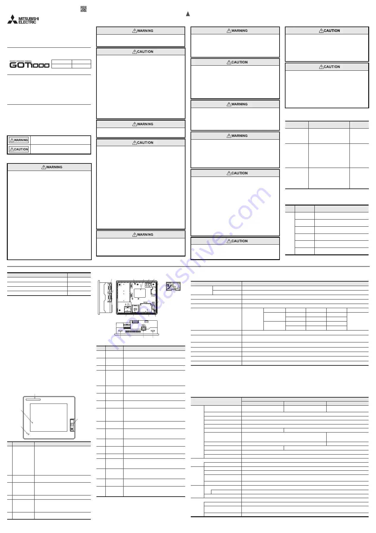
2. Part Name
2.1 Front
For the PC connection, refer to the following.
GT14 User’s Manual
Bundled item
Quantity
Mounting brackets
4
Mounting screws: M4 x 35mm (1.38")
4
Dust-/Water-proof packing
1
GT14 General Description (This manual)
1
No
Name
Specifications
1) Display screen
Displays the utility screen and the user creation
screen.
GT1455-QTBD(E):320
240 dots, TFT color liquid
crystal
GT1450-QMBD(E):320
240 dots, TFT monochrome
(white/black) liquid crystal, 16
scales
GT1450-QLBD(E):320
240 dots, STN monochrome
(white/black) liquid crystal, 16
scales
2) Touch panel
For operating the touch switches in the utility screen
and the user creation screen
3) POWER LED
Lit in green: Power is correctly supplied
Lit in orange: Screen saving
Blinking in orange/green: Blown backlight bulb
Not lit: Power is not supplied
4) Logo label
Removable
5) USB interface
USB interface for connecting a personal computer
(Device)
O S i n s t a l l a t i o n , p r o j e c t d a t a d o w n l o a d , FA
transparent
6)
USB environmental
protection cover
Opens/Closes when the USB interface is used.
1) 2)
5) 6)
3)
4)
2.2 Back/Bottom
For the connection to the controller (PLC, microcomputer board, bar code reader,
RFID, etc) or PC, refer to the following.
GT14 User’s Manual
No.
Name
Specifications
1)
RS-232
interface
For communicating with controller or personal computer
(D-sub 9-pin male)
2)
RS-422/485
interface
For communicating with controller (D-sub 9-pin female)
3)
USB interface
For data transfer, data storage USB interface (Host)
4)
Hole for
preventing
USB
cable
disconnection
Hole for fixing the USB cable with a cable tie (such as
Insulock) to prevent disconnection
5)
Rating plate
(nameplate)
--
6)
SD card
interface
Interface for installing the SD card to GOT
7)
SD card
access LED
Lit: SD card accessed
Not lit: SD card not accessed
8)
SD card
access switch
Switch for prohibiting access to SD card before removing
the SD card from the GOT
ON: SD card being accessed (SD card removal prohibited)
OFF: No access to SD card (SD card removal possible)
9)
Battery
GT11-50BAT battery for storing clock data, alarm history
and recipe data
10)
Battery cover
Open or close when replacing the battery.
Opened and closed when the terminating resistor is
changed over
11)
Power terminal
Power terminal and FG terminal
(for power supply (24VDC) to GOT and grounding)
12)
Power terminal
cover
Open or close when connecting a power terminal.
(Color: transparent)
13)
Reset switch
Hardware reset switch (Use an isolated rod to operate.)
14)
Terminating
resistor
selector switch
Terminating resistor selector switch of RS-422/485
(330
/OPEN/110
)
15)
Ethernet
communication
status LED
SD RD: Turns on in green during data communication,
100M:Turns on in green during 100Mbps transmission.
16)
Ethernet
interface
For connecting the equipment through Ethernet
(RJ-45 connector)
17)
Hole for unit
installation
fitting
Hole for the inserting installation fittings (accessory) during
the GOT installation to the panel
(4 holes at top and bottom)
1)
2)
15)
10)
3)
11) 12)
6)
13)
8)
7)
5)
4)
Battery cover opened
14)
9)
17)
17)
16)
3. Specifications
3.1 General Specifications
*1 Do not use or store the GOT under pressure higher than the atmospheric pressure of altitude 0m (0ft.). Failure to observe this instruction may cause a malfunction.
When the air inside the control panel is purged by pressurization, the surface sheet may be lifted by high pressure. As a result, the touch panel may be difficult to press,
and the sheet may be peeled off.
*2 This indicates the section of the power supply to which the equipment is assumed to be connected between the public electrical power distribution network and the
machinery within the premises.
Category
applies to equipment for which electrical power is supplied from fixed facilities.
The surge voltage withstand level for up to the raged voltage of 300 V is 2500 V.
*3 This index indicates the degree to which conductive material is generated in the environment where the equipment is used.
In pollution degree 2, only non-conductive pollution occurs but temporary conductivity may be produced due to condensation.
3.2 Performance Specifications
Item
Specifications
Operating ambient
temperature
Display section
0 to 50
C
Other than display section 0 to 55
C (When mounted horizontally), 0 to 50
C (When mounted vertically)
Storage ambient temperature
-20 to 60
C
Operating ambient humidity
10 to 90% RH, non-condensing (STN liquid crystal type to be stored at or below 39
C WBT.)
Storage ambient humidity
10 to 90% RH, non-condensing (STN liquid crystal type to be stored at or below 39
C WBT.)
Vibration resistance
Conforms to JIS
B3502 and
IEC61131-2
Frequency
Acceleration
Half-amplitude
Sweep Count
Under intermittent
vibration
5 to 8.4Hz
--
3.5mm
10 times each in X,
Y and Z directions
8.4 to 150Hz
9.8m/s
2
--
Under continuous
vibration
5 to 8.4Hz
--
1.75mm
8.4 to 150Hz
4.9m/s
2
--
Shock resistance
Conforms to JIS B3502, IEC 61131-2 (147 m/s
2
, 3 times each in X, Y and Z directions)
Operating atmosphere
Must be free of lamp black, corrosive gas, flammable gas, or excessive amount of electro conductive dust particles and
must be no direct sunlight. (Same as for saving)
Operating altitude
*1
2000 m (6562 ft) max.
Installation location
Inside control panel
Overvoltage category
*2
or less
Pollution degree
*3
2 or less
Cooling method
Self-cooling
Item
Specifications
GT1455-QTBD(E)
GT1450-QMBD(E)
GT1450-QLBD(E)
Display
section
*1
Type
TFT color liquid crystal
TFT monochrome (white/black)
liquid crystal
STN monochrome (white/black)
liquid crystal
Screen size
5.7"
Resolution
320
240 dots
Display size
W115(4.53)
H86(3.39)[mm](inch) (Horizontal format)
Display character
16-dot standard font: 20 characters
15 lines, 12-dot standard font: 26 characters
20 lines
Display color
65536 colors
Monochrome (white/black), 16 scales
Display angle
*2
Left/Right: 80 degrees, Top: 80 degrees, Bottom: 60 degrees (Horizontal format)
Left/Right: 45 degrees,
Top: 20 degrees,
Bottom: 40 degrees (Horizontal format)
Contrast adjustment
--
32-level adjustmen
Intensity of LCD only
400[cd/m
2
]
300[cd/m
2
]
Intensity adjustment
8-level adjustment
Life
Approx. 50,000h. (Time for display intensity to become 1/5 at operating ambient temperature of 25
C)
Backlight
LED (irreplaceable by a user) Backlight off/screen saving time can be set.
*3
Life
Approx. 70,000h or longer (Time for display intensity reaches 50% at the operating ambient temperature of 25
C)
To u c h
panel
*4
Type
Analog resistive film touch panel
Key size
Minimum 2
2 dots (per key)
N u m b e r o f p o i n ts t o u c h e d
simultaneously
Simultaneous presses not allowed. (Only 1 point can be touched.)
Life
1 million times or more (operating force 0.98N max.)
Memory
C drive
*5
Flash memory (Internal), for storing project data (9Mbytes) and OS
Life (Number of write times) 100,000 times
D drive
SRAM (Internal), 512kbytes (battery backup)
Battery
GT11-50BAT lithium battery
Type
Magnesium maganese dioxide lithium primary battery
Backup target
Clock data, alarm history, recipe data, time action setting value, advanced alarm/advanced recipe, logging, hardcopy and
SRAM user area
Life
Approx. 5 years (Operating ambient temperature of 25
C)
GT1455-QTBD(E), GT1450-QMBD(E)
GT1450-QLBD(E)
GT14 General Description
This manual describes the part names, dimensions, mounting, and specifications
of the product. Before use, read this manual and manuals of relevant products
fully to acquire proficiency in handling and operating the product. Make sure to
learn all the product information, safety information, and precautions.
And, store this manual in a safe place so that you can take it out and read it
whenever necessary. Always forward it to the end user.
Registration
Ethernet is a trademark of Xerox Corporation in the United States. The company
name and the product name to be described in this manual are the registered
trademarks or trademarks of each company.
Effective April 2018
Specifications are subject to change without notice.
2011 MITSUBISHI ELECTRIC CORPORATION
Manual Number
JY997D43901H
Date
April 2018


