background image

ENGLISH

Fresh Master

Models:

GUF-50RDH3 

 GUF-50RD3

GUF-100RDH3 

 GUF-100RD3

Installation Instructions

(For use by dealer/contractor)

For use with the R410A&R407C&R22

• Please take the time to read through these instruc-

tions before commencing with the installation work.
They will help to install the Fresh Master properly and
safely.

• The separate Operating Instructions are for the user.

Make sure that they are handed over to the customer.

The warranty will not apply to damage resulting
from failure to follow the warnings and precau-
tions set forth in the Installation Instructions.

GUF-50RDH3 shown above.

Humidifier function not available on GUF-50RD3 and
GUF-100RD3.

Contents

1. Safety precautions ............................................ 2-4
2. Accessories .......................................................... 5
3. Outline drawings .................................................. 5
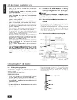
4. Selecting an installation site ................................. 6
5. Installing the Fresh Master ................................ 6-7
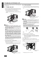
6. Supply pipe and drain pipe work .......................... 8
7. Refrigerant pipe work ...................................... 9-11
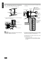
8. Electrical wiring ............................................. 12-16
9. Feature settings ............................................ 17-19
10. Test run ......................................................... 19-20
11. Troubleshooting ................................................. 21

Summary of Contents for Fresh Master GUF-100RD3

Page 1: ...r Make sure that they are handed over to the customer The warranty will not apply to damage resulting from failure to follow the warnings and precau tions set forth in the Installation Instructions GUF 50RDH3 shown above Humidifier function not available on GUF 50RD3 and GUF 100RD3 Contents 1 Safety precautions 2 4 2 Accessories 5 3 Outline drawings 5 4 Selecting an installation site 6 5 Installin...

Page 2: ...followed Indicates a part which must be grounded Beware of electric shock This symbol is displayed on the main unit label Colour Yellow Warning Carefully read the labels affixed to the main unit 1 1 Installation s s s s s After you have read this manual keep it and the Installation Manual in a safe place for easy reference whenever a question arises If the unit is going to be operated by another p...

Page 3: ...d tubes The pipes must have the wall thickness as shown in the table below In addition be sure that the inner and outer surfaces of the pipes are clean and free of hazardous sulphur oxides dust dirt shaving particles oils moisture or any other contaminant It is strictly prohibited to use pipes with thin wall not listed in the above table If the inside of pipe is contaminated it could cause deterio...

Page 4: ...sult in a general unit failure or fire Do not wash the Fresh Master Washing them may cause an electric shock Be careful that the installation base is not damaged by long use If the damage is left uncorrected the unit may fall and cause personal injury or property damage Be very careful about product transportation Only one person should not carry the product if it weighs more than 20 kg Fresh Mast...

Page 5: ... changed Lossnay core Air filter High efficiency filter Fan Maintenance space Inspection opening Inspection opening Solenoid valve unit with pressure regulator Solenoid valve Heat exchange unit Humidifying element Maintenance space Power cable installation port Can install upper area of ceiling suspension fixture GUF 100RDH3 100RD3 Location at which the duct direction can be changed Humidifying el...

Page 6: ...aracter ised by their connection to the public low voltage power supply system 5 Installing the Fresh Master 5 1 Fixing hanging bolts Use M10 or M12 hanging bolts The bolts and washers should be supplied in the field Give site of suspension strong structure Hanging structure Ceiling The ceiling structure varies from one building to another For detailed information consult your construction company...

Page 7: ...e the four mounting screws that were removed to attach the flange cover 5 5 Connecting the ducts 1 Fit the ducts securely into the duct connecting flanges and wind aluminium tape available from a field supply around them to pre vent air leaks 2 Suspend the ducts from the ceiling so that their weight will not be applied to the Fresh Master 3 The exhaust outdoor and supply ducts must be covered with...

Page 8: ...prevention work for extremely cold areas Perform freeze prevention by wrapping a freeze prevention heater field supply on the supply pipe Wrap a freeze prevention heater all the way to the Fresh Master Insulation work must be performed upon the heater as well yy yy yy 6 2 Drain pipe work 1 Connect a vinyl chloride VP25 elbow to the drain discharge port 2 The drain pipe must be properly insulated f...

Page 9: ... Be sure to use non oxidative brazing for brazing to ensure that no foreign matter or moisture enter into the pipe s Be sure to apply refrigerating machine oil over the flare con nection seating surface and tighten the connection using a double spanner s Provide a metal brace to support the refrigerant pipe so that no load is imparted to the Fresh Master end pipe This metal brace should be provide...

Page 10: ...dimension A Pipe Dia mm ø6 35 1 4 ø9 52 3 8 ø12 7 1 2 ø15 88 5 8 0 0 5 0 0 5 0 0 5 0 0 5 1 0 1 5 1 0 1 5 1 0 1 5 1 0 1 5 1 5 2 0 1 5 2 0 1 5 2 5 1 5 2 5 R410A Flare Tool When using conventional flare tool R22 R407C Dimension A mm Rigid clutch type Imperial wing nut type Dice Copper pipe A øB R 0 4 R 0 8 Copper Pipe O D ø6 35 ø9 52 ø12 7 ø15 88 8 7 9 1 12 8 13 2 16 2 16 6 19 3 19 7 Flare Dimension ...

Page 11: ...op Seal the slit securely so that there are no openings Be sure to mount the insulation so that the slit is on the top Notes 1 Insert the flare nut into the field refrigerant piping Pull the insulation material back at the area where it will be flared then return it to its original position after performing the flare work Exposing copper piping may result in condensation forming Be extremely caref...

Page 12: ...ghten ing rod or telephone earth cable Incomplete grounding may cause a risk of electric shock 8 2 Types of control cables 1 Wiring M NET transmission cables Types of transmission cables Design wiring in accordance with the following table Table 1 Cable cross sectional area 1 25 mm2 to 2 00 mm2 Table 1 2 Remote controller cables Building clinic hospital or communi cations station without noise sup...

Page 13: ...branch NO set Remote control terminal M NET transmission terminal Shield Connector power supply Relay Transformer Damper motor Limit switch Power supply monitor MA Remote contoller Power supply monitor M NET Power supply monitor 1 12 11 10 9 8 7 2 A B S GREEN YELLOW BLACK PINK ORANGE WHITE RED GREEN YELLOW SUPPLY FAN EXHAUST FAN ORANGE BLUE WHITE RED BLACK PINK GREEN YELLOW M2 M1 BROWN PINK PINK C...

Page 14: ...ROWN PURPLE FAN1 FAN4 BLACK YELLOW YELLOW RED WHITE WHITE ORANGE PURPLE ORANGE BLUE WHITE RED BLACK PINK GREEN YELLOW GREEN YELLOW BLACK PINK ORANGE WHITE RED GREEN YELLOW M1 M2 FAN2 FAN3 3 1 ZNR901 X05 X04 X07 X06 FUSE1 BROWN BROWN BLUE RED BLUE BROWN YELLOW TR CN3T CNT CND1 CND2 GREEN SW4 SW5 TM3 TM2 X09 X08 X03 BREAKER 16A TM1 220 240V 50Hz POWERSUPPLY N L PE N L B S A 2 7 8 9 10 11 1 12 PAR F2...

Page 15: ...smis sion cable within 200 m If the distance is more than 10 m use a 1 25 mm2 to 2 0 mm2 cable For using the MA Remote controller Connect the 1 and 2 on Fresh Master TM2 to the Remote control ler Non polarized 2 wire Connect the Remote controller s transmis sion cable within 200 m S B A 2 1 S B A 2 1 S B A 2 1 24 to 30 V DC between M1 and M2 Longest wiring length L1 L2 L4 or L1 L3 less than 200 m ...

Page 16: ... the control of moisture environment The suitable model in this stage Uncharged a contact turns on when atmospheric moisture content becomes less than your preset minimum allowable percentage Screw Controller box cover Terminal block TM1 Terminal block for power supply cable for TM1 Grounding wire PG connection or the like Power supply cable Insulation sheet Terminal block for TM2 M NET transmissi...

Page 17: ...o not touch Damper motor test operation test operation when ON Solenoid valve test operation for humidifier water supply test operation when ON Do not touch GUF 50 100RD3 Auto recovery during power failure active when on Power supply ON OFF test operation when on SW12 SW11 SW14 Second digit First digit Branch No SW3 GUF 50 100RDH3 OFF ON Synchronous air conditioning switch async when ON Humidifier...

Page 18: ...ating capability can be saved lower temperature than normal 9 3 6 Heat operation stop temperature setting GUF 50 100RDH3 only Stopping the heating operation when synchronous with the indoor unit It becomes invalid when SW3 1 is ON 3 4 5 3 4 5 3 4 5 3 4 5 3 4 5 3 4 5 3 4 5 3 4 5 9 3 7 Exhaust fan operation setting Setting the exhaust fan operation although the supply fan will stop when defrosting d...

Page 19: ...peed from con trollers Following the selected fan speed from con trollers High fan speed mode notch constantly on high Low fan speed mode notch constantly on low Switch SW2 OFF ON Mode Effective Ineffective Switch SW3 OFF ON Mode Fresh Master s return air Built in the Remote controller Switch SW3 OFF ON When operating the Fresh Master directly using the Remote controller SW3 1 is ON Operational Pr...

Page 20: ...r displays the temperature of the indoor unit s liquid pipe on the temperature display section during test run Depending on the model the Remote controller displays This function is not available when pressing the Up down airflow selection button This is not a malfunction Phenomenon 1 No Remote controller display appears at all 2 No Remote controller display appears at all 3 Inspection code 6600 f...

Page 21: ... firmly connected When no problem is discovered after checking the above item Has 10 minutes passed since system boot up Has group registration been made Has the Fresh Master address been changed When no problem is discovered after checking the above items The Fresh Master which is linked with air conditioner cannot be group registered other than the interlock setting with the Remote controller Ma...

Page 22: ...22 ENGLISH ...

Reviews: