background image

1

Mitsubishi Electric Corporation  

FREQROL 
Inverter Driver

1

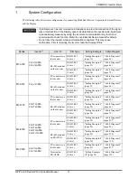
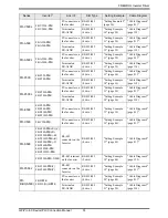
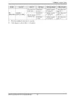
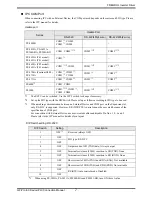
System Configuration....................................................................................................... 3

2

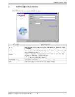
External Devices Selection .............................................................................................. 9

3

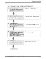
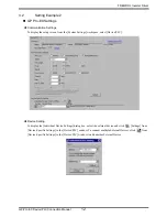
Communication Settings ................................................................................................ 10

4

Setup Items .................................................................................................................... 58

5

Cable Diagrams ............................................................................................................. 62

6

Supported Devices....................................................................................................... 139

7

Device Code and Address Code.................................................................................. 149

8

Error Messages............................................................................................................ 150

Summary of Contents for FREQROL

Page 1: ...ation FREQROL Inverter Driver 1 System Configuration 3 2 External Devices Selection 9 3 Communication Settings 10 4 Setup Items 58 5 Cable Diagrams 62 6 Supported Devices 139 7 Device Code and Address Code 149 8 Error Messages 150 ...

Page 2: ...vices Selection Select a model series of the External Device and its connection method 2 External Devices Selection page 9 3 Communication Settings This section shows setting examples for communicating between the Display and the External Device 3 Communication Settings page 10 4 Setup Items This section describes communication setup items on the Display Set the Display s communication settings in...

Page 3: ...e 3 page 14 Cable Diagram 3 page 72 FR A701 FR A721 K PU connector on the Inverter RS 422 485 4 wire Setting Example 1 page 10 Cable Diagram 1 page 62 RS 485 terminal on the Inverter RS 422 485 4 wire Setting Example 2 page 12 Cable Diagram 2 page 66 RS 422 485 2 wire Setting Example 3 page 14 Cable Diagram 3 page 72 FR F700 FR F720 K FR F740 K PU connector on the Inverter RS 422 485 4 wire Settin...

Page 4: ... Inverter RS 422 485 4 wire Setting Example 13 page 34 Cable Diagram 4 page 81 2 Terminal on FR A5NR RS 422 485 4 wire Setting Example 14 page 36 Cable Diagram 7 page 118 FR E500 FR E520 K FR E540 K FR E520S K FR E510W K PU connector on the Inverter RS 422 485 4 wire Setting Example 15 page 38 Cable Diagram 4 page 81 2 FR C500 FR C520 K PU connector on the Inverter RS 422 485 4 wire Setting Exampl...

Page 5: ... page 52 Cable Diagram 1 page 62 RS 485 terminal on the Inverter RS 422 485 4 wire Setting Example 23 page 54 Cable Diagram 2 page 66 RS 422 485 2 wire Setting Example 24 page 56 Cable Diagram 3 page 72 1 varies depending on each inverter s capacity 2 Cable Diagram 1 can be used for 1 1 Connection Series Inverter 1 Link I F SIO Type Setting Example Cable Diagram ...

Page 6: ... 1 1 Connection 1 n Connection Display External Device Display External Device External Device External Device Maximum number of External Devices 16 Display External Device External Device External Device External Device External Device External Device Maximum number of External Devices 32 ...

Page 7: ...used COM3 2 COM3 2 PS 3711A COM1 1 COM2 2 COM2 2 COM2 2 PS4000 3 3 When making communication between an External Device and COM port on the Expansion slot only RS 232C is supported However ER DTR CTS control cannot be executed because of the specification of COM port For connection with External Device use user created cables and disable Pin Nos 1 4 6 and 9 Please refer to the IPC manual for detai...

Page 8: ... to RD RXD None 7 OFF Short circuit of SDA TXA and RDA RXA Not available 8 OFF Short circuit of SDB TXB and RDB RXB Not available 9 OFF RS RTS Auto control mode Disabled 10 OFF DIP Switch Setting Description 1 OFF Reserved always OFF 2 ON SIO type RS 422 485 3 ON 4 OFF Output mode of SD TXD data Always output 5 OFF Terminal resistance 220Ω insertion to SD TXD None 6 OFF Terminal resistance 220Ω in...

Page 9: ...be connected Select Mitsubishi Electric Corporation Series Select a model series of the External Device to be connected and connection method Select FREQROL Inverter In System configuration check to make sure the external device to which you are connecting is supported in FREQROL Inverter 1 System Configuration page 3 Use System Area Not available for this driver Port Select the Display port to be...

Page 10: ...ample 1 GP Pro EX Settings Communication Settings To display the setup screen from the System Settings workspace select Device PLC Device Setting To display the Individual Device Settings dialog box select the external device and click Settings from Device Specific Settings in the Device PLC window To connect multiple External Devices click from Device Specific Settings in the Device PLC window to...

Page 11: ...g parameter number with M dial 5 Press SET key to display the current setting value 6 Set the setting value with M dial 7 Press SET key to confirm the setting value Setting Parameter Number Setting Value Setup Description 117 0 PU communication station number 118 192 PU communication speed 119 1 PU communication stop bit length 120 2 PU communication parity check 121 1 Number of PU communication r...

Page 12: ...reen from the System Settings workspace select Device PLC Device Setting To display the Individual Device Settings dialog box select the external device and click Settings from Device Specific Settings in the Device PLC window To connect multiple External Devices click from Device Specific Settings in the Device PLC window to add another External Device ...

Page 13: ...with M dial 5 Press SET key to display the current setting value 6 Set the setting value with M dial 7 Press SET key to confirm the setting value Setting Parameter Number Setting Value Setup Description 331 0 RS 485 communication station 332 192 RS 485 communication speed 333 1 RS 485 communication stop bit length 334 2 RS 485 communication parity check selection 335 1 RS 485 communication retry c...

Page 14: ...reen from the System Settings workspace select Device PLC Device Setting To display the Individual Device Settings dialog box select the external device and click Settings from Device Specific Settings in the Device PLC window To connect multiple External Devices click from Device Specific Settings in the Device PLC window to add another External Device ...

Page 15: ...with M dial 5 Press SET key to display the current setting value 6 Set the setting value with M dial 7 Press SET key to confirm the setting value Setting Parameter Number Setting Value Setup Description 331 0 RS 485 communication station 332 192 RS 485 communication speed 333 1 RS 485 communication stop bit length 334 2 RS 485 communication parity check selection 335 1 RS 485 communication retry c...

Page 16: ...reen from the System Settings workspace select Device PLC Device Setting To display the Individual Device Settings dialog box select the external device and click Settings from Device Specific Settings in the Device PLC window To connect multiple External Devices click from Device Specific Settings in the Device PLC window to add another External Device ...

Page 17: ...g parameter number with M dial 5 Press SET key to display the current setting value 6 Set the setting value with M dial 7 Press SET key to confirm the setting value Setting Parameter Number Setting Value Setup Description 117 0 PU communication station number 118 192 PU communication speed 119 1 PU communication stop bit length 120 2 PU communication parity check 121 1 Number of PU communication r...

Page 18: ...reen from the System Settings workspace select Device PLC Device Setting To display the Individual Device Settings dialog box select the external device and click Settings from Device Specific Settings in the Device PLC window To connect multiple External Devices click from Device Specific Settings in the Device PLC window to add another External Device ...

Page 19: ...with M dial 5 Press SET key to display the current setting value 6 Set the setting value with M dial 7 Press SET key to confirm the setting value Setting Parameter Number Setting Value Setup Description 331 0 RS 485 communication station 332 192 RS 485 communication speed 333 1 RS 485 communication stop bit length 334 2 RS 485 communication parity check selection 335 1 RS 485 communication retry c...

Page 20: ...reen from the System Settings workspace select Device PLC Device Setting To display the Individual Device Settings dialog box select the external device and click Settings from Device Specific Settings in the Device PLC window To connect multiple External Devices click from Device Specific Settings in the Device PLC window to add another External Device ...

Page 21: ...with M dial 5 Press SET key to display the current setting value 6 Set the setting value with M dial 7 Press SET key to confirm the setting value Setting Parameter Number Setting Value Setup Description 331 0 RS 485 communication station 332 192 RS 485 communication speed 333 1 RS 485 communication stop bit length 334 2 RS 485 communication parity check selection 335 1 RS 485 communication retry c...

Page 22: ...reen from the System Settings workspace select Device PLC Device Setting To display the Individual Device Settings dialog box select the external device and click Settings from Device Specific Settings in the Device PLC window To connect multiple External Devices click from Device Specific Settings in the Device PLC window to add another External Device ...

Page 23: ...rameter number with M dial 5 Press SET key to display the current setting value 6 Set the setting value with M dial 7 Press SET key to confirm the setting value Setting Parameter Number Setting Value Setup Description 117 0 PU communication station number 118 192 PU communication speed 119 1 PU communication stop bit length 120 2 PU communication parity check 121 1 Number of PU communication retri...

Page 24: ...reen from the System Settings workspace select Device PLC Device Setting To display the Individual Device Settings dialog box select the external device and click Settings from Device Specific Settings in the Device PLC window To connect multiple External Devices click from Device Specific Settings in the Device PLC window to add another External Device ...

Page 25: ...rameter number with M dial 5 Press SET key to display the current setting value 6 Set the setting value with M dial 7 Press SET key to confirm the setting value Setting Parameter Number Setting Value Setup Description 117 0 PU communication station number 118 192 PU communication speed 119 1 PU communication stop bit length 120 2 PU communication parity check 121 1 Number of PU communication retri...

Page 26: ...reen from the System Settings workspace select Device PLC Device Setting To display the Individual Device Settings dialog box select the external device and click Settings from Device Specific Settings in the Device PLC window To connect multiple External Devices click from Device Specific Settings in the Device PLC window to add another External Device ...

Page 27: ... the parameter number 6 Press SET key 7 Press up key or down key to display the least significant digit of the parameter number 8 Press SET key to display the current setting value 9 Press up key or down key to set the setting value 10 Press SET key for 1 5 seconds to write the setting value Setting Parameter Number Setting Value Setup Description 117 0 Communication station number 118 192 Communi...

Page 28: ...creen from the System Settings workspace select Device PLC Device Setting To display the Individual Device Settings dialog box select the external device and click Settings from Device Specific Settings in the Device PLC window To connect multiple External Devices click from Device Specific Settings in the Device PLC window to add another External Device ...

Page 29: ...git of the parameter number 6 Press SET key 7 Press up key or down key to display the least significant digit of the parameter number 8 Press SET key to display the current setting value 9 Press up key or down key to set the setting value 10 Press SET key for 1 5 seconds to write the setting value Setting Parameter Number Setting Value Setup Description 331 0 Communication station number 332 192 C...

Page 30: ...creen from the System Settings workspace select Device PLC Device Setting To display the Individual Device Settings dialog box select the external device and click Settings from Device Specific Settings in the Device PLC window To connect multiple External Devices click from Device Specific Settings in the Device PLC window to add another External Device ...

Page 31: ...igit of the parameter number 6 Press SET key 7 Press up key or down key to display the least significant digit of the parameter number 8 Press SET key to display the current setting value 9 Press up key or down key to set the setting value 10 Press SET key for 1 5 seconds to write the setting value Setting Parameter Number Setting Value Setup Description 117 0 Station number 118 192 Communication ...

Page 32: ...creen from the System Settings workspace select Device PLC Device Setting To display the Individual Device Settings dialog box select the external device and click Settings from Device Specific Settings in the Device PLC window To connect multiple External Devices click from Device Specific Settings in the Device PLC window to add another External Device ...

Page 33: ...the middle digit of the parameter number 6 Press SET key 7 Press up key or down key to display the least significant digit of the parameter number 8 Press SET key to display the current setting value 9 Press up key or down key to set the setting value 10 Press SET key for 1 5 seconds to write the setting value Setting Parameter Number Setting Value Setup Description 331 0 Communication station num...

Page 34: ...creen from the System Settings workspace select Device PLC Device Setting To display the Individual Device Settings dialog box select the external device and click Settings from Device Specific Settings in the Device PLC window To connect multiple External Devices click from Device Specific Settings in the Device PLC window to add another External Device ...

Page 35: ... the parameter number 6 Press SET key 7 Press up key or down key to display the least significant digit of the parameter number 8 Press SET key to display the current setting value 9 Press up key or down key to set the setting value 10 Press SET key for 1 5 seconds to write the setting value Setting Parameter Number Setting Value Setup Description 117 0 Communication station number 118 192 Communi...

Page 36: ...creen from the System Settings workspace select Device PLC Device Setting To display the Individual Device Settings dialog box select the external device and click Settings from Device Specific Settings in the Device PLC window To connect multiple External Devices click from Device Specific Settings in the Device PLC window to add another External Device ...

Page 37: ...ay the middle digit of the parameter number 6 Press SET key 7 Press up key or down key to display the least significant digit of the parameter number 8 Press SET key to display the current setting value 9 Press up key or down key to set the setting value 10 Press SET key for 1 5 seconds to write the setting value Setting Parameter Number Setting Value Setup Description 331 0 Inverter station numbe...

Page 38: ...creen from the System Settings workspace select Device PLC Device Setting To display the Individual Device Settings dialog box select the external device and click Settings from Device Specific Settings in the Device PLC window To connect multiple External Devices click from Device Specific Settings in the Device PLC window to add another External Device ...

Page 39: ...git of the parameter number 6 Press SET key 7 Press up key or down key to display the least significant digit of the parameter number 8 Press SET key to display the current setting value 9 Press up key or down key to set the setting value 10 Press SET key for 1 5 seconds to write the setting value Setting Parameter Number Setting Value Setup Description 117 0 Communication station number 118 192 C...

Page 40: ...creen from the System Settings workspace select Device PLC Device Setting To display the Individual Device Settings dialog box select the external device and click Settings from Device Specific Settings in the Device PLC window To connect multiple External Devices click from Device Specific Settings in the Device PLC window to add another External Device ...

Page 41: ...ect FR C500 in the Model 5 Select the size of inverter in the Size 6 Click OK 7 Click Confirmed 8 Click OFFLINE to change ONLINE 9 Select the All List Format from the Parameter menu to display the All List Format window 10 Set the communication settings as follows 11 Click Blk Write This completes the setting of the External Device Setting Parameter Number Setting Value Setup Description 331 0 Com...

Page 42: ...creen from the System Settings workspace select Device PLC Device Setting To display the Individual Device Settings dialog box select the external device and click Settings from Device Specific Settings in the Device PLC window To connect multiple External Devices click from Device Specific Settings in the Device PLC window to add another External Device ...

Page 43: ...r setting mode 4 Display the setting parameter number with M dial 5 Press SET key to display the current setting value 6 Set the setting value with M dial 7 Press SET key to confirm the setting value Setting Parameter Number Setting Value Setup Description n1 0 n1 Communication station number n2 192 n2 Communication speed n3 1 n3 Stop bit length n4 2 n4 Parity check presence absence n5 1 n5 Number...

Page 44: ...creen from the System Settings workspace select Device PLC Device Setting To display the Individual Device Settings dialog box select the external device and click Settings from Device Specific Settings in the Device PLC window To connect multiple External Devices click from Device Specific Settings in the Device PLC window to add another External Device ...

Page 45: ...4 Display the setting parameter number with M dial 5 Press SET key to display the current setting value 6 Set the setting value with M dial 7 Press SET key to confirm the setting value Setting Parameter Number Setting Value Setup Description n1 0 n1 Communication station number n2 192 n2 Communication speed n3 1 n3 Stop bit length n4 2 n4 Parity check presence absence n5 1 n5 Number of communicati...

Page 46: ...creen from the System Settings workspace select Device PLC Device Setting To display the Individual Device Settings dialog box select the external device and click Settings from Device Specific Settings in the Device PLC window To connect multiple External Devices click from Device Specific Settings in the Device PLC window to add another External Device ...

Page 47: ...r setting mode 4 Display the setting parameter number with M dial 5 Press SET key to display the current setting value 6 Set the setting value with M dial 7 Press SET key to confirm the setting value Setting Parameter Number Setting Value Setup Description n1 0 n1 Communication station number n2 192 n2 Communication speed n3 1 n3 Stop bit length n4 2 n4 Parity check presence absence n5 1 n5 Number...

Page 48: ...creen from the System Settings workspace select Device PLC Device Setting To display the Individual Device Settings dialog box select the external device and click Settings from Device Specific Settings in the Device PLC window To connect multiple External Devices click from Device Specific Settings in the Device PLC window to add another External Device ...

Page 49: ...igit of the parameter number 6 Press SET key 7 Press up key or down key to display the least significant digit of the parameter number 8 Press SET key to display the current setting value 9 Press up key or down key to set the setting value 10 Press SET key for 1 5 seconds to write the setting value Setting Parameter Number Setting Value Setup Description 117 0 Station number 118 192 Communication ...

Page 50: ...creen from the System Settings workspace select Device PLC Device Setting To display the Individual Device Settings dialog box select the external device and click Settings from Device Specific Settings in the Device PLC window To connect multiple External Devices click from Device Specific Settings in the Device PLC window to add another External Device ...

Page 51: ...ay the middle digit of the parameter number 6 Press SET key 7 Press up key or down key to display the least significant digit of the parameter number 8 Press SET key to display the current setting value 9 Press up key or down key to set the setting value 10 Press SET key for 1 5 seconds to write the setting value Setting Parameter Number Setting Value Setup Description 331 0 Inverter station numbe...

Page 52: ...creen from the System Settings workspace select Device PLC Device Setting To display the Individual Device Settings dialog box select the external device and click Settings from Device Specific Settings in the Device PLC window To connect multiple External Devices click from Device Specific Settings in the Device PLC window to add another External Device ...

Page 53: ...e setting parameter number with M dial 5 Press SET key to display the current setting value 6 Set the setting value with M dial 7 Press SET key to confirm the setting value Setting Parameter Number Setting Value Setup Description 117 0 PU communication station number 118 192 PU communication speed 119 1 PU communication stop bit length 120 2 PU communication parity check 121 1 Number of PU communi...

Page 54: ...creen from the System Settings workspace select Device PLC Device Setting To display the Individual Device Settings dialog box select the external device and click Settings from Device Specific Settings in the Device PLC window To connect multiple External Devices click from Device Specific Settings in the Device PLC window to add another External Device ...

Page 55: ...with M dial 5 Press SET key to display the current setting value 6 Set the setting value with M dial 7 Press SET key to confirm the setting value Setting Parameter Number Setting Value Setup Description 331 0 RS 485 communication station 332 192 RS 485 communication speed 333 1 RS 485 communication stop bit length 334 2 RS 485 communication parity check selection 335 1 RS 485 communication retry c...

Page 56: ...creen from the System Settings workspace select Device PLC Device Setting To display the Individual Device Settings dialog box select the external device and click Settings from Device Specific Settings in the Device PLC window To connect multiple External Devices click from Device Specific Settings in the Device PLC window to add another External Device ...

Page 57: ...with M dial 5 Press SET key to display the current setting value 6 Set the setting value with M dial 7 Press SET key to confirm the setting value Setting Parameter Number Setting Value Setup Description 331 0 RS 485 communication station 332 192 RS 485 communication speed 333 1 RS 485 communication stop bit length 334 2 RS 485 communication parity check selection 335 1 RS 485 communication retry c...

Page 58: ...etup Items Setup Description SIO Type Select the SIO type to communicate with the External Device In the communication setting confirm the serial interface specifications of the Display and set SIO Type correctly If you select an SIO type the serial interface does not support we cannot guarantee the operation Please refer to the manual of the Display for more detail on the serial interface specifi...

Page 59: ...mission and reception data Timeout Use an integer from 1 to 127 to enter the time s for which the Display waits for the response from the External Device Retry In case of no response from the External Device use an integer from 0 to 255 to enter how many times the Display retransmits the command Wait To Send Use an integer from 0 to 255 to enter standby time ms for the Display from receiving packe...

Page 60: ...ge in the offline mode depends on the Display in use Please refer to the Reference manual for details Setup Items Setup Description SIO Type Select the SIO type to communicate with the External Device In the communication setting confirm the serial interface specifications of the Display and set SIO Type correctly If you select an SIO type the serial interface does not support we cannot guarantee ...

Page 61: ...sponse from the External Device Retry In case of no response from the External Device use an integer from 0 to 255 to enter how many times the Display retransmits the command Wait To Send ms Use an integer from 0 to 255 to enter standby time ms for the Display from receiving packets to transmitting next commands Setup Items Setup Description Device PLC Name Select the External Device to set Device...

Page 62: ...se and interference affect communication Cable Diagram 1 Display Connection Port Cable Notes GP3000 1 COM1 AGP 3302B COM2 ST 2 COM2 LT COM1 IPC 3 1 All GP3000 models except AGP 3302B 2 All ST models except AST 3211A and AST 3302B 3 Only the COM port which can communicate by RS 422 485 4 wire can be used IPC COM Port page 7 1A COM port conversion adapter by Pro face CA3 ADPCOM 01 Terminal block con...

Page 63: ...ector 5 554720 3 Tyco Electronics AMP K K SDA SDB RDA RDB SG External Device side RJ45 connector Signal name 5 4 3 6 1 Pin RDA RDB SDA SDB SG FG Signal name Display side Terminal Block CA3 ADPTRM 01 CA3 ADPCOM 01 Display User created cable RDA RDB SDA SDB SG ERA CSA ERB CSB FG Signal name 1 2 3 7 5 4 8 9 6 Shell Pin Display side D Sub 9pin socket SDA SDB RDA RDB SG Signal name 5 4 3 6 1 Pin Extern...

Page 64: ...6 1 Pin RDA RDB SDA SDB SG FG Signal name Display side Terminal Block User created cable CA3 ADPTRM 01 CA4 ADPONL 01 Display TERMRX RDA RDB SDA SDB SG TERMTX FG Signal name 1 2 7 3 8 5 9 Shell Pin Display side D Sub 9pin plug SDA SDB RDA RDB SG Signal name 5 4 3 6 1 Pin External Device side RJ45 connector CA4 ADPONL 01 Display User created cable ...

Page 65: ...r Driver GP Pro EX Device PLC Connection Manual 65 1E RDA RDB SDA SDB SG ERA CSA ERB CSB Signal name Display side Terminal block SDA SDB RDA RDB SG Signal name 5 4 3 6 1 Pin External Device side RJ45 connector Display ...

Page 66: ...4 wire can be used IPC COM Port page 7 2A COM port conversion adapter by Pro face CA3 ADPCOM 01 Terminal block conversion adapter by Pro face CA3 ADPTRM 01 User created cable Cable length 500m or less 2B User created cable GP3000 4 COM2 4 All GP3000 models except GP 3200 series and AGP 3302B 2C Online adapter by Pro face CA4 ADPONL 01 Terminal block conversion adapter by Pro face CA3 ADPTRM 01 Use...

Page 67: ...SDA SDB SG FG Signal name Display side Terminal Block Shield CA3 ADPTRM 01 CA3 ADPCOM 01 Display User created cable Signal name SDA1 TXD1 SDB1 TXD1 RDA1 RXD1 RDB1 RXD1 SG GND External Device side Terminal Block External Device side Terminal Block TERM RDA RDB SDA SDB SG FG Signal name Display side Terminal Block Shield Shield CA3 ADPTRM 01 CA3 ADPCOM 01 Display User created cable Signal name SDA1 ...

Page 68: ... Display side D Sub 9pin socket External Device side Terminal Block Shield Termination resistance 100Ω 1 2W Display Signal name SDA1 TXD1 SDB1 TXD1 RDA1 RXD1 RDB1 RXD1 SG GND External Device side Terminal Block External Device side Terminal Block Shield Shield RDA RDB SDA SDB SG ERA CSA ERB CSB FG Signal name 1 2 3 7 5 4 8 9 6 Shell Pin Display side D Sub 9pin socket Termination resistance 100Ω 1 ...

Page 69: ...SDA SDB SG FG Signal name Display side Terminal Block Shield CA3 ADPTRM 01 CA4 ADPONL 01 Display User created cable Signal name SDA1 TXD1 SDB1 TXD1 RDA1 RXD1 RDB1 RXD1 SG GND External Device side Terminal Block External Device side Terminal Block TERM RDA RDB SDA SDB SG FG Signal name Display side Terminal Block Shield Shield CA3 ADPTRM 01 CA4 ADPONL 01 Display User created cable Signal name SDA1 ...

Page 70: ...in Display side D Sub 9pin plug CA4 ADPONL 01 Display External Device side Terminal Block Shield User created cable Signal name SDA1 TXD1 SDB1 TXD1 RDA1 RXD1 RDB1 RXD1 SG GND External Device side Terminal Block External Device side Terminal Block Shield Shield CA4 ADPONL 01 Display TERMRX RDA RDB SDA SDB SG TERMTX FG Signal name 1 2 7 3 8 5 9 Shell Pin Display side D Sub 9pin plug User created cab...

Page 71: ...Device in the chain DIP Switch No Set Value 1 OFF 2 OFF 3 ON 4 ON RDA RDB SDA SDB SG ERA CSA ERB CSB Signal name Display side Terminal block External Device side Terminal Block Shield Termination resistance 1 Display Signal name SDA1 TXD1 SDB1 TXD1 RDA1 RXD1 RDB1 RXD1 SG GND External Device side Terminal Block External Device side Terminal Block Shield Shield RDA RDB SDA SDB SG ERA CSA ERB CSB Sig...

Page 72: ...ss 3B User created cable GP3000 3 COM2 3 All GP3000 models except GP 3200 series and AGP 3302B 3C Online adapter by Pro face CA4 ADPONL 01 Terminal block conversion adapter by Pro face CA3 ADPTRM 01 User created cable 3D Online adapter by Pro face CA4 ADPONL 01 User created cable IPC 4 4 Only the COM port which can communicate by RS 422 485 2 wire can be used IPC COM Port page 7 3E COM port conver...

Page 73: ...SDA SDB SG FG Signal name Display side Terminal Block Shield CA3 ADPTRM 01 CA3 ADPCOM 01 Display User created cable Signal name SDA1 TXD1 SDB1 TXD1 RDA1 RXD1 RDB1 RXD1 SG GND External Device side Terminal Block External Device side Terminal Block TERM RDA RDB SDA SDB SG FG Signal name Display side Terminal Block Shield Shield CA3 ADPTRM 01 CA3 ADPCOM 01 Display User created cable Signal name SDA1 ...

Page 74: ... Display side D Sub 9pin socket Shield External Device side Terminal Block Termination resistance 100Ω 1 2W Display Signal name SDA1 TXD1 SDB1 TXD1 RDA1 RXD1 RDB1 RXD1 SG GND External Device side Terminal Block External Device side Terminal Block RDA RDB SDA SDB SG ERA CSA ERB CSB FG Signal name 1 2 3 7 5 4 8 9 6 Shell Pin Display side D Sub 9pin socket Termination resistance 100Ω 1 2W Shield Shie...

Page 75: ...SDA SDB SG FG Signal name Display side Terminal Block Shield CA3 ADPTRM 01 CA4 ADPONL 01 Display User created cable Signal name SDA1 TXD1 SDB1 TXD1 RDA1 RXD1 RDB1 RXD1 SG GND External Device side Terminal Block External Device side Terminal Block TERM RDA RDB SDA SDB SG FG Signal name Display side Terminal Block Shield Shield CA3 ADPTRM 01 CA4 ADPONL 01 Display User created cable Signal name SDA1 ...

Page 76: ...in Display side D Sub 9pin plug CA4 ADPONL 01 Display External Device side Terminal Block Shield User created cable Signal name SDA1 TXD1 SDB1 TXD1 RDA1 RXD1 RDB1 RXD1 SG GND External Device side Terminal Block External Device side Terminal Block CA4 ADPONL 01 Display TERMRX RDA RDB SDA SDB SG TERMTX FG Signal name 1 2 7 3 8 5 9 Shell Pin Display side D Sub 9pin plug Shield Shield User created cab...

Page 77: ...SDA SDB SG FG Signal name Display side Terminal Block Shield CA3 ADPTRM 01 CA3 ADPCOM 01 Display User created cable Signal name SDA1 TXD1 SDB1 TXD1 RDA1 RXD1 RDB1 RXD1 SG GND External Device side Terminal Block TERM RDA RDB SDA SDB SG FG Signal name Display side Terminal Block Shield CA3 ADPTRM 01 CA3 ADPCOM 01 Display User created cable External Device side Terminal Block Shield Signal name SDA1 ...

Page 78: ... Display side D Sub 9pin socket Shield External Device side Terminal Block Termination resistance 100Ω 1 2W Display Signal name SDA1 TXD1 SDB1 TXD1 RDA1 RXD1 RDB1 RXD1 SG GND External Device side Terminal Block DATA DATA NC NC GND SG ERA CSA ERB CSB FG Signal name 1 2 3 7 5 4 8 9 6 Shell Pin Display side D Sub 9pin socket Termination resistance 100Ω 1 2W Shield Display External Device side Termina...

Page 79: ...Device in the chain DIP Switch No Set Value 1 OFF 2 OFF 3 ON 4 ON RDA RDB SDA SDB SG ERA CSA ERB CSB Signal name Display side Terminal block Shield External Device side Terminal Block Termination resistance 1 Display Signal name SDA1 TXD1 SDB1 TXD1 RDA1 RXD1 RDB1 RXD1 SG GND External Device side Terminal Block External Device side Terminal Block RDA RDB SDA SDB SG ERA CSA ERB CSB Signal name Displ...

Page 80: ...on the last External Device in the chain In COM on the GP 4107 the SG and FG terminals are isolated Signal name Pin Display side D Sub 9pin plug Shield External Device side Terminal Block Termination resistance 100Ω 1 2W Display Signal name SDA1 TXD1 SDB1 TXD1 RDA1 RXD1 RDB1 RXD1 SG GND 3 8 1 2 5 4 6 7 9 Shell NC NC GND SG RS RTS 5V NC NC FG LINE LINE External Device side Terminal Block Signal nam...

Page 81: ...ser created cable Cable length 500m or less 4B User created cable GP3000 4 COM2 4 All GP3000 models except GP 3200 series and AGP 3302B 4C Online adapter by Pro face CA4 ADPONL 01 Terminal block conversion adapter by Pro face CA3 ADPTRM 01 User created cable 4D Online adapter by Pro face CA4 ADPONL 01 User created cable GP 4106 COM1 4E User created cable Item Type Manufacturer Cable FR CB20 1 1 Di...

Page 82: ...isplay side Terminal Block Distributor side RJ45 connector Distributor side RJ45 connector Distributor side RJ45 connector External Device side RJ45 connector Distributor BMJ 8P FR CB20 cable 5 4 3 6 1 Pin SDA SDB RDA RDB SG 5 4 3 6 1 Pin SDA SDB RDA RDB SG 5 4 3 6 1 Pin SDA SDB RDA RDB SG 5 4 3 6 1 Pin Termination resistance 100Ω 1 4W User created cable CA3 ADPTRM 01 CA3 ADPCOM 01 Display ...

Page 83: ...stributor side RJ45 connector Distributor side RJ45 connector Distributor side RJ45 connector External Device side RJ45 connector External Device side RJ45 connector Distributor BMJ 8 FR CB20 cable 5 4 3 6 1 Pin SDA SDB RDA RDB SG 5 4 3 6 1 Pin SDA SDB RDA RDB SG 5 4 3 6 1 Pin SDA SDB RDA RDB SG 5 4 3 6 1 Pin Distributor BMJ 8P FR CB20 cable SDA SDB RDA RDB SG 5 4 3 6 1 Pin SDA SDB RDA RDB SG 5 4 ...

Page 84: ...ributor side RJ45 connector Distributor BMJ 8P FR CB20 cable 5 4 3 6 1 Pin SDA SDB RDA RDB SG 5 4 3 6 1 Pin SDA SDB RDA RDB SG 5 4 3 6 1 Pin SDA SDB RDA RDB SG 5 4 3 6 1 Pin Termination resistance 100Ω 1 4W Signal name Signal name Signal name Signal name Display side D Sub 9pin socket Display RDA RDB SDA SDB SG ERA CSA ERB CSB FG Signal name 1 2 3 7 5 4 8 9 6 Shell Pin Termination resistance 100Ω ...

Page 85: ... 8 FR CB20 cable FR CB20 cable 5 4 3 6 1 Pin SDA SDB RDA RDB SG 5 4 3 6 1 Pin SDA SDB RDA RDB SG 5 4 3 6 1 Pin SDA SDB RDA RDB SG 5 4 3 6 1 Pin Distributor BMJ 8P SDA SDB RDA RDB SG 5 4 3 6 1 Pin SDA SDB RDA RDB SG 5 4 3 6 1 Pin Termination resistance 100Ω 1 4W SDA SDB RDA RDB SG 5 4 3 6 1 Pin SG RDB RDA SDB SDA 1 6 3 4 5 Pin Signal name Signal name Signal name Signal name Signal name Signal name ...

Page 86: ... connector Distributor side RJ45 connector External Device side RJ45 connector Distributor side RJ45 connector Distributor BMJ 8P FR CB20 cable 5 4 3 6 1 Pin SDA SDB RDA RDB SG 5 4 3 6 1 Pin SDA SDB RDA RDB SG 5 4 3 6 1 Pin SDA SDB RDA RDB SG 5 4 3 6 1 Pin Termination resistance 100Ω 1 4W User created cable Signal name Signal name Signal name Signal name CA3 ADPTRM 01 CA4 ADPONL 01 Display ...

Page 87: ...ector Distributor side RJ45 connector Distributor side RJ45 connector Distributor BMJ 8 FR CB20 cable 5 4 3 6 1 Pin SDA SDB RDA RDB SG 5 4 3 6 1 Pin SDA SDB RDA RDB SG 5 4 3 6 1 Pin SDA SDB RDA RDB SG 5 4 3 6 1 Pin Distributor BMJ 8P FR CB20 cable SDA SDB RDA RDB SG 5 4 3 6 1 Pin SDA SDB RDA RDB SG 5 4 3 6 1 Pin Termination resistance 100Ω 1 4W SDA SDB RDA RDB SG 5 4 3 6 1 Pin SG RDB RDA SDB SDA 1...

Page 88: ...r Distributor side RJ45 connector Distributor BMJ 8P FR CB20 cable 5 4 3 6 1 Pin SDA SDB RDA RDB SG 5 4 3 6 1 Pin SDA SDB RDA RDB SG 5 4 3 6 1 Pin SDA SDB RDA RDB SG 5 4 3 6 1 Pin Termination resistance 100Ω 1 4W User created cable Signal name Signal name CA4 ADPONL 01 Display TERMRX RDA RDB SDA SDB SG TERMTX FG Signal name 1 2 7 3 8 5 9 Shell Pin Display side D Sub 9pin plug Signal name Signal na...

Page 89: ...utor BMJ 8 FR CB20 cable 5 4 3 6 1 Pin SDA SDB RDA RDB SG 5 4 3 6 1 Pin SDA SDB RDA RDB SG 5 4 3 6 1 Pin SDA SDB RDA RDB SG 5 4 3 6 1 Pin Distributor BMJ 8P FR CB20 cable SDA SDB RDA RDB SG 5 4 3 6 1 Pin SDA SDB RDA RDB SG 5 4 3 6 1 Pin Termination resistance 100Ω 1 4W SDA SDB RDA RDB SG 5 4 3 6 1 Pin SG RDB RDA SDB SDA 1 6 3 4 5 Pin User created cable Signal name Signal name Signal name Signal na...

Page 90: ...e RJ45 connector Distributor side RJ45 connector Distributor BMJ 8P FR CB20 cable 5 4 3 6 1 Pin SDA SDB RDA RDB SG 5 4 3 6 1 Pin SDA SDB RDA RDB SG 5 4 3 6 1 Pin SDA SDB RDA RDB SG 5 4 3 6 1 Pin Termination resistance 100Ω 1 4W Signal name Signal name Signal name Signal name Display side Terminal block Display RDA RDB SDA SDB SG ERA CSA ERB CSB Signal name Termination resistance 1 ...

Page 91: ... connector Distributor side RJ45 connector Distributor side RJ45 connector Distributor side RJ45 connector Distributor BMJ 8 FR CB20 cable FR CB20 cable 5 4 3 6 1 Pin SDA SDB RDA RDB SG 5 4 3 6 1 Pin SDA SDB RDA RDB SG 5 4 3 6 1 Pin SDA SDB RDA RDB SG 5 4 3 6 1 Pin Distributor BMJ 8P SDA SDB RDA RDB SG 5 4 3 6 1 Pin SDA SDB RDA RDB SG 5 4 3 6 1 Pin Termination resistance 100Ω 1 4W SDA SDB RDA RDB ...

Page 92: ...C Online adapter by Pro face CA4 ADPONL 01 Terminal block conversion adapter by Pro face CA3 ADPTRM 01 User created cable 5D Online adapter by Pro face CA4 ADPONL 01 User created cable IPC 4 4 Only the COM port which can communicate by RS 422 485 2 wire can be used IPC COM Port page 7 5E COM port conversion adapter by Pro face CA3 ADPCOM 01 Terminal block conversion adapter by Pro face CA3 ADPTRM ...

Page 93: ...de RJ45 connector Distributor side RJ45 connector External Device side RJ45 connector Distributor side RJ45 connector Distributor BMJ 8P 5 4 3 6 1 Pin SDA SDB RDA RDB SG 5 4 3 6 1 Pin SDA SDB RDA RDB SG 5 4 3 6 1 Pin SDA SDB RDA RDB SG 5 4 3 6 1 Pin Termination resistance 100Ω 1 4W User created cable Signal name Signal name Signal name Signal name CA3 ADPTRM 01 CA3 ADPCOM 01 Display ...

Page 94: ...side RJ45 connector Distributor side RJ45 connector Distributor side RJ45 connector Distributor BMJ 8 5 4 3 6 1 Pin SDA SDB RDA RDB SG 5 4 3 6 1 Pin SDA SDB RDA RDB SG 5 4 3 6 1 Pin SDA SDB RDA RDB SG 5 4 3 6 1 Pin Distributor BMJ 8P SDA SDB RDA RDB SG 5 4 3 6 1 Pin SDA SDB RDA RDB SG 5 4 3 6 1 Pin Termination resistance 100Ω 1 4W SDA SDB RDA RDB SG 5 4 3 6 1 Pin SG RDB RDA SDB SDA 1 6 3 4 5 Pin U...

Page 95: ... External Device side RJ45 connector Distributor BMJ 8P 5 4 3 6 1 Pin SDA SDB RDA RDB SG 5 4 3 6 1 Pin SDA SDB RDA RDB SG 5 4 3 6 1 Pin SDA SDB RDA RDB SG 5 4 3 6 1 Pin Termination resistance 100Ω 1 4W Signal name Signal name Signal name Signal name Display side D Sub 9pin socket RDA RDB SDA SDB SG ERA CSA ERB CSB FG Signal name 1 2 3 7 5 4 8 9 6 Shell Pin Termination resistance 100Ω 1 4W Display ...

Page 96: ...or Distributor BMJ 8 5 4 3 6 1 Pin SDA SDB RDA RDB SG 5 4 3 6 1 Pin SDA SDB RDA RDB SG 5 4 3 6 1 Pin SDA SDB RDA RDB SG 5 4 3 6 1 Pin Distributor BMJ 8P SDA SDB RDA RDB SG 5 4 3 6 1 Pin SDA SDB RDA RDB SG 5 4 3 6 1 Pin Termination resistance 100Ω 1 4W SDA SDB RDA RDB SG 5 4 3 6 1 Pin SG RDB RDA SDB SDA 1 6 3 4 5 Pin Signal name Signal name Signal name Signal name Signal name Signal name Signal nam...

Page 97: ...de RJ45 connector Distributor side RJ45 connector Distributor side RJ45 connector External Device side RJ45 connector Distributor BMJ 8P 5 4 3 6 1 Pin SDA SDB RDA RDB SG 5 4 3 6 1 Pin SDA SDB RDA RDB SG 5 4 3 6 1 Pin SDA SDB RDA RDB SG 5 4 3 6 1 Pin Termination resistance 100Ω 1 4W User created cable Signal name Signal name Signal name Signal name CA3 ADPTRM 01 CA4 ADPONL 01 Display ...

Page 98: ... RJ45 connector Distributor side RJ45 connector External Device side RJ45 connector Distributor BMJ 8 5 4 3 6 1 Pin SDA SDB RDA RDB SG 5 4 3 6 1 Pin SDA SDB RDA RDB SG 5 4 3 6 1 Pin SDA SDB RDA RDB SG 5 4 3 6 1 Pin Distributor BMJ 8P SDA SDB RDA RDB SG 5 4 3 6 1 Pin SDA SDB RDA RDB SG 5 4 3 6 1 Pin Termination resistance 100Ω 1 4W SDA SDB RDA RDB SG 5 4 3 6 1 Pin SG RDB RDA SDB SDA 1 6 3 4 5 Pin U...

Page 99: ...ctor External Device side RJ45 connector Distributor BMJ 8P 5 4 3 6 1 Pin SDA SDB RDA RDB SG 5 4 3 6 1 Pin SDA SDB RDA RDB SG 5 4 3 6 1 Pin SDA SDB RDA RDB SG 5 4 3 6 1 Pin Termination resistance 100Ω 1 4W User created cable Signal name Signal name Signal name Signal name CA4 ADPONL 01 Display TERMRX RDA RDB SDA SDB SG TERMTX FG Signal name 1 2 7 3 8 5 9 Shell Pin Display side D Sub 9pin plug ...

Page 100: ...nector Distributor BMJ 8 5 4 3 6 1 Pin SDA SDB RDA RDB SG 5 4 3 6 1 Pin SDA SDB RDA RDB SG 5 4 3 6 1 Pin SDA SDB RDA RDB SG 5 4 3 6 1 Pin Distributor BMJ 8P SDA SDB RDA RDB SG 5 4 3 6 1 Pin SDA SDB RDA RDB SG 5 4 3 6 1 Pin Termination resistance 100Ω 1 4W SDA SDB RDA RDB SG 5 4 3 6 1 Pin SG RDB RDA SDB SDA 1 6 3 4 5 Pin User created cable Signal name Signal name Signal name Signal name Signal name...

Page 101: ...side RJ45 connector Distributor side RJ45 connector Distributor BMJ 8P 5 4 3 6 1 Pin SDA SDB RDA RDB SG 5 4 3 6 1 Pin SDA SDB RDA RDB SG 5 4 3 6 1 Pin SDA SDB RDA RDB SG 5 4 3 6 1 Pin Termination resistance 100Ω 1 4W User created cable Signal name Signal name Signal name Signal name TERM RDA RDB SDA SDB SG FG Signal name Display side Terminal Block CA3 ADPTRM 01 CA3 ADPCOM 01 Display ...

Page 102: ...e RJ45 connector Distributor BMJ 8 5 4 3 6 1 Pin SDA SDB RDA RDB SG 5 4 3 6 1 Pin SDA SDB RDA RDB SG 5 4 3 6 1 Pin SDA SDB RDA RDB SG 5 4 3 6 1 Pin Distributor BMJ 8P SDA SDB RDA RDB SG 5 4 3 6 1 Pin SDA SDB RDA RDB SG 5 4 3 6 1 Pin Termination resistance 100Ω 1 4W SDA SDB RDA RDB SG 5 4 3 6 1 Pin SG RDB RDA SDB SDA 1 6 3 4 5 Pin User created cable Signal name Signal name Signal name Signal name S...

Page 103: ...External Device side RJ45 connector Distributor BMJ 8P 5 4 3 6 1 Pin SDA SDB RDA RDB SG 5 4 3 6 1 Pin SDA SDB RDA RDB SG 5 4 3 6 1 Pin SDA SDB RDA RDB SG 5 4 3 6 1 Pin Termination resistance 100Ω 1 4W Signal name Signal name Signal name Signal name Display side D Sub 9pin socket DATA DATA NC NC GND SG ERA CSA ERB CSB FG Signal name 1 2 3 7 5 4 8 9 6 Shell Pin Termination resistance 100Ω 1 4W Displ...

Page 104: ... Distributor BMJ 8 5 4 3 6 1 Pin SDA SDB RDA RDB SG 5 4 3 6 1 Pin SDA SDB RDA RDB SG 5 4 3 6 1 Pin SDA SDB RDA RDB SG 5 4 3 6 1 Pin Distributor BMJ 8P SDA SDB RDA RDB SG 5 4 3 6 1 Pin SDA SDB RDA RDB SG 5 4 3 6 1 Pin Termination resistance 100Ω 1 4W SDA SDB RDA RDB SG 5 4 3 6 1 Pin SG RDB RDA SDB SDA 1 6 3 4 5 Pin Signal name Signal name Signal name Signal name Signal name Signal name Signal name ...

Page 105: ...or side RJ45 connector External Device side RJ45 connector Distributor BMJ 8P 5 4 3 6 1 Pin SDA SDB RDA RDB SG 5 4 3 6 1 Pin SDA SDB RDA RDB SG 5 4 3 6 1 Pin SDA SDB RDA RDB SG 5 4 3 6 1 Pin Termination resistance 100Ω 1 4W Signal name Signal name Signal name Signal name Display side Terminal block RDA RDB SDA SDB SG ERA CSA ERB CSB Signal name Termination resistance 1 Display ...

Page 106: ...r side RJ45 connector External Device side RJ45 connector Distributor side RJ45 connector External Device side RJ45 connector Distributor BMJ 8 5 4 3 6 1 Pin SDA SDB RDA RDB SG 5 4 3 6 1 Pin SDA SDB RDA RDB SG 5 4 3 6 1 Pin SDA SDB RDA RDB SG 5 4 3 6 1 Pin Distributor BMJ 8P SDA SDB RDA RDB SG 5 4 3 6 1 Pin SDA SDB RDA RDB SG 5 4 3 6 1 Pin Termination resistance 100Ω 1 4W SDA SDB RDA RDB SG 5 4 3 ...

Page 107: ... External Device side RJ45 connector Distributor BMJ 8P 5 4 3 6 1 Pin SDA SDB RDA RDB SG 5 4 3 6 1 Pin SDA SDB RDA RDB SG 5 4 3 6 1 Pin SDA SDB RDA RDB SG 5 4 3 6 1 Pin Termination resistance 100Ω 1 4W Signal name Signal name Signal name Signal name Display side D Sub 9pin plug Signal name Pin Termination resistance 100Ω 1 4W Display 3 8 1 2 5 4 6 7 9 Shell NC NC GND SG RS RTS 5V NC NC FG LINE LIN...

Page 108: ...ice side RJ45 connector Distributor side RJ45 connector External Device side RJ45 connector Distributor BMJ 8 5 4 3 6 1 Pin SDA SDB RDA RDB SG 5 4 3 6 1 Pin SDA SDB RDA RDB SG 5 4 3 6 1 Pin SDA SDB RDA RDB SG 5 4 3 6 1 Pin Distributor BMJ 8P SDA SDB RDA RDB SG 5 4 3 6 1 Pin SDA SDB RDA RDB SG 5 4 3 6 1 Pin Termination resistance 100Ω 1 4W SDA SDB RDA RDB SG 5 4 3 6 1 Pin SG RDB RDA SDB SDA 1 6 3 4...

Page 109: ...ess 6B User created cable GP3000 3 COM2 3 All GP3000 models except GP 3200 series and AGP 3302B 6C Online adapter by Pro face CA4 ADPONL 01 Terminal block conversion adapter by Pro face CA3 ADPTRM 01 User created cable 6D Online adapter by Pro face CA4 ADPONL 01 User created cable IPC 4 4 Only the COM port which can communicate by RS 422 485 2 wire can be used IPC COM Port page 7 6E COM port conve...

Page 110: ...mination resistance 100Ω 1 2W DA DB SG External Device side Terminal Block Signal name DA DB SG User created cable TERM RDA RDB SDA SDB SG FG Signal name Display side Terminal Block Shield Shield CA3 ADPTRM 01 CA3 ADPCOM 01 Display DA DB SG External Device side Terminal Block Signal name DA DB SG Termination resistance 100Ω 1 2W DA DB SG External Device side Terminal Block Signal name DA DB SG Use...

Page 111: ... SDB SG ERA CSA ERB CSB FG Signal name 1 2 3 7 5 4 8 9 6 Shell Pin Termination resistance 100Ω 1 2W Shield Display Shield DA DB SG External Device side Terminal Block Signal name DA DB SG Termination resistance 100Ω 1 2W DA DB SG External Device side Terminal Block Signal name DA DB SG Display side D Sub 9pin socket RDA RDB SDA SDB SG ERA CSA ERB CSB FG Signal name 1 2 3 7 5 4 8 9 6 Shell Pin Term...

Page 112: ...mination resistance 100Ω 1 2W DA DB SG External Device side Terminal Block Signal name DA DB SG User created cable TERM RDA RDB SDA SDB SG FG Signal name Display side Terminal Block Shield Shield CA3 ADPTRM 01 CA4 ADPONL 01 Display DA DB SG External Device side Terminal Block Signal name DA DB SG Termination resistance 100Ω 1 2W DA DB SG External Device side Terminal Block Signal name DA DB SG Use...

Page 113: ...X RDA RDB SDA SDB SG TERMTX FG Signal name 1 2 7 3 8 5 9 Shell Pin Display side D Sub 9pin plug User created cable Shield Shield DA DB SG External Device side Terminal Block Signal name DA DB SG Termination resistance 100Ω 1 2W DA DB SG External Device side Terminal Block Signal name DA DB SG CA4 ADPONL 01 Display TERMRX RDA RDB SDA SDB SG TERMTX FG Signal name 1 2 7 3 8 5 9 Shell Pin Display side...

Page 114: ...mination resistance 100Ω 1 2W DA DB SG External Device side Terminal Block Signal name DA DB SG User created cable TERM RDA RDB SDA SDB SG FG Signal name Display side Terminal Block Shield Shield CA3 ADPTRM 01 CA3 ADPCOM 01 Display DA DB SG External Device side Terminal Block Signal name DA DB SG Termination resistance 100Ω 1 2W DA DB SG External Device side Terminal Block Signal name DA DB SG Use...

Page 115: ... GND SG ERA CSA ERB CSB FG Signal name 1 2 3 7 5 4 8 9 6 Shell Pin Termination resistance 100Ω 1 2W Shield Display Shield DA DB SG External Device side Terminal Block Signal name DA DB SG Termination resistance 100Ω 1 2W DA DB SG External Device side Terminal Block Signal name DA DB SG Display side D Sub 9pin socket DATA DATA NC NC GND SG ERA CSA ERB CSB FG Signal name 1 2 3 7 5 4 8 9 6 Shell Pin ...

Page 116: ...N Termination resistance 100Ω 1 2W DA DB SG External Device side Terminal Block Signal name DA DB SG Display side Terminal block RDA RDB SDA SDB SG ERA CSA ERB CSB Signal name Termination resistance 1 Shield Display Shield DA DB SG External Device side Terminal Block Signal name DA DB SG Termination resistance 100Ω 1 2W DA DB SG External Device side Terminal Block Signal name DA DB SG RDA RDB SDA ...

Page 117: ...ice side Terminal Block Signal name DA DB SG Display side D Sub 9pin plug Signal name Pin Termination resistance 100Ω 1 2W Shield Display 3 8 1 2 5 4 6 7 9 Shell NC NC GND SG RS RTS 5V NC NC FG LINE LINE Shield DA DB SG External Device side Terminal Block Signal name DA DB SG Termination resistance 100Ω 1 2W DA DB SG External Device side Terminal Block Signal name DA DB SG Display side D Sub 9pin ...

Page 118: ...4 wire can be used IPC COM Port page 7 7A COM port conversion adapter by Pro face CA3 ADPCOM 01 Terminal block conversion adapter by Pro face CA3 ADPTRM 01 User created cable Cable length 500m or less 7B User created cable GP3000 4 COM2 4 All GP3000 models except GP 3200 series and AGP 3302B 7C Online adapter by Pro face CA4 ADPONL 01 Terminal block conversion adapter by Pro face CA3 ADPTRM 01 Use...

Page 119: ...Terminal Block Shield CA3 ADPTRM 01 CA3 ADPCOM 01 Display SDA SDB RDA RDB SG RDR Signal name User created cable SDA SDB RDA RDB SG RDR External Device side Terminal Block External Device side Terminal Block Signal name TERM RDA RDB SDA SDB SG FG Signal name Display side Terminal Block Shield Shield CA3 ADPTRM 01 CA3 ADPCOM 01 Display SDA SDB RDA RDB SG RDR Signal name User created cable ...

Page 120: ... 1 2 3 7 5 4 8 9 6 Shell Pin Termination resistance 100Ω 1 2W Shield SDA SDB RDA RDB SG RDR Signal name Display SDA SDB RDA RDB SG RDR External Device side Terminal Block External Device side Terminal Block Signal name Shield Display side D Sub 9pin socket RDA RDB SDA SDB SG ERA CSA ERB CSB FG Signal name 1 2 3 7 5 4 8 9 6 Shell Pin Termination resistance 100Ω 1 2W Shield SDA SDB RDA RDB SG RDR Si...

Page 121: ...Terminal Block Shield CA3 ADPTRM 01 CA4 ADPONL 01 Display SDA SDB RDA RDB SG RDR Signal name User created cable SDA SDB RDA RDB SG RDR External Device side Terminal Block External Device side Terminal Block Signal name TERM RDA RDB SDA SDB SG FG Signal name Display side Terminal Block Shield Shield CA3 ADPTRM 01 CA4 ADPONL 01 Display SDA SDB RDA RDB SG RDR Signal name User created cable ...

Page 122: ...DA RDB SDA SDB TERMTX SG FG Signal name 1 2 7 3 8 9 5 Shell Pin Display side D Sub 9pin plug User created cable SDA SDB RDA RDB RDR SG External Device side Terminal Block External Device side Terminal Block Signal name Shield Shield SDA SDB RDA RDB RDR SG Signal name CA4 ADPONL 01 Display TERMRX RDA RDB SDA SDB TERMTX SG FG Signal name 1 2 7 3 8 9 5 Shell Pin Display side D Sub 9pin plug User crea...

Page 123: ...Value 1 OFF 2 OFF 3 ON 4 ON External Device side Terminal Block Display side Terminal block RDA RDB SDA SDB SG ERA CSA ERB CSB Signal name Termination resistance 1 Shield SDA SDB RDA RDB SG RDR Signal name Display SDA SDB RDA RDB SG RDR External Device side Terminal Block External Device side Terminal Block Signal name Shield Display side Terminal block RDA RDB SDA SDB SG ERA CSA ERB CSB Signal na...

Page 124: ...4 wire can be used IPC COM Port page 7 8A COM port conversion adapter by Pro face CA3 ADPCOM 01 Terminal block conversion adapter by Pro face CA3 ADPTRM 01 User created cable Cable length 500m or less 8B User created cable GP3000 4 COM2 4 All GP3000 models except GP 3200 series and AGP 3302B 8C Online adapter by Pro face CA4 ADPONL 01 Terminal block conversion adapter by Pro face CA3 ADPTRM 01 Use...

Page 125: ... chain SDA SDB RDA RDB SG External Device side Terminal Block Signal name TERM RDA RDB SDA SDB SG FG Signal name Display side Terminal Block Shield CA3 ADPTRM 01 CA3 ADPCOM 01 Display User created cable SDA SDB RDA RDB SG SDA SDB RDA RDB SG External Device side Terminal Block External Device side Terminal Block Signal name TERM RDA RDB SDA SDB SG FG Signal name Display side Terminal Block Shield S...

Page 126: ...A CSA ERB CSB FG Signal name 1 2 3 7 5 4 8 9 6 Shell Pin Display side D Sub 9pin socket External Device side Terminal Block SDA SDB RDA RDB SG Signal name Shield Termination resistance 100Ω 1 2W Display SDA SDB RDA RDB SG SDA SDB RDA RDB SG External Device side Terminal Block External Device side Terminal Block Signal name Shield Shield SDA SDB RDA RDB SG Signal name RDA RDB SDA SDB SG ERA CSA ERB...

Page 127: ... chain SDA SDB RDA RDB SG External Device side Terminal Block Signal name TERM RDA RDB SDA SDB SG FG Signal name Display side Terminal Block Shield CA3 ADPTRM 01 CA4 ADPONL 01 Display User created cable SDA SDB RDA RDB SG SDA SDB RDA RDB SG External Device side Terminal Block External Device side Terminal Block Signal name TERM RDA RDB SDA SDB SG FG Signal name Display side Terminal Block Shield S...

Page 128: ...B SDA SDB SG TERMTX FG Signal name 1 2 7 3 8 5 9 Shell Pin Display side D Sub 9pin plug CA4 ADPONL 01 Display SDA SDB RDA RDB SG External Device side Terminal Block Signal name Shield User created cable SDA SDB RDA RDB SG SDA SDB RDA RDB SG External Device side Terminal Block External Device side Terminal Block Signal name Shield Shield CA4 ADPONL 01 Display SDA SDB RDA RDB SG Signal name TERMRX R...

Page 129: ...or switch to the 100Ω position only on the last External Device in the chain DIP Switch No Set Value 1 OFF 2 OFF 3 ON 4 ON RDA RDB SDA SDB SG ERA CSA ERB CSB Signal name Display side Terminal block External Device side Terminal Block SDA SDB RDA RDB SG Signal name Shield Termination resistance 1 Display SDA SDB RDA RDB SG SDA SDB RDA RDB SG External Device side Terminal Block External Device side ...

Page 130: ...ess 9B User created cable GP3000 3 COM2 3 All GP3000 models except GP 3200 series and AGP 3302B 9C Online adapter by Pro face CA4 ADPONL 01 Terminal block conversion adapter by Pro face CA3 ADPTRM 01 User created cable 9D Online adapter by Pro face CA4 ADPONL 01 User created cable IPC 4 4 Only the COM port which can communicate by RS 422 485 2 wire can be used IPC COM Port page 7 9E COM port conve...

Page 131: ... chain SDA SDB RDA RDB SG External Device side Terminal Block Signal name TERM RDA RDB SDA SDB SG FG Signal name Display side Terminal Block Shield CA3 ADPTRM 01 CA3 ADPCOM 01 Display User created cable SDA SDB RDA RDB SG SDA SDB RDA RDB SG External Device side Terminal Block External Device side Terminal Block Signal name TERM RDA RDB SDA SDB SG FG Signal name Display side Terminal Block Shield S...

Page 132: ...A CSA ERB CSB FG Signal name 1 2 3 7 5 4 8 9 6 Shell Pin Display side D Sub 9pin socket Shield SDA SDB RDA RDB SG External Device side Terminal Block Signal name Termination resistance 100Ω 1 2W Display SDA SDB RDA RDB SG SDA SDB RDA RDB SG External Device side Terminal Block External Device side Terminal Block Signal name SDA SDB RDA RDB SG Signal name RDA RDB SDA SDB SG ERA CSA ERB CSB FG Signal...

Page 133: ... chain SDA SDB RDA RDB SG External Device side Terminal Block Signal name TERM RDA RDB SDA SDB SG FG Signal name Display side Terminal Block Shield CA3 ADPTRM 01 CA4 ADPONL 01 Display User created cable SDA SDB RDA RDB SG SDA SDB RDA RDB SG External Device side Terminal Block External Device side Terminal Block Signal name TERM RDA RDB SDA SDB SG FG Signal name Display side Terminal Block Shield S...

Page 134: ...B SDA SDB SG TERMTX FG Signal name 1 2 7 3 8 5 9 Shell Pin Display side D Sub 9pin plug CA4 ADPONL 01 Display SDA SDB RDA RDB SG External Device side Terminal Block Signal name Shield User created cable SDA SDB RDA RDB SG SDA SDB RDA RDB SG External Device side Terminal Block External Device side Terminal Block Signal name CA4 ADPONL 01 Display SDA SDB RDA RDB SG Signal name TERMRX RDA RDB SDA SDB...

Page 135: ... chain SDA SDB RDA RDB SG External Device side Terminal Block Signal name TERM RDA RDB SDA SDB SG FG Signal name Display side Terminal Block Shield CA3 ADPTRM 01 CA3 ADPCOM 01 Display User created cable SDA SDB RDA RDB SG SDA SDB RDA RDB SG External Device side Terminal Block Signal name TERM RDA RDB SDA SDB SG FG Signal name Display side Terminal Block Shield CA3 ADPTRM 01 CA3 ADPCOM 01 Display U...

Page 136: ...A CSA ERB CSB FG Signal name 1 2 3 7 5 4 8 9 6 Shell Pin Display side D Sub 9pin socket Shield SDA SDB RDA RDB SG External Device side Terminal Block Signal name Termination resistance 100Ω 1 2W Display SDA SDB RDA RDB SG SDA SDB RDA RDB SG External Device side Terminal Block Signal name DATA DATA NC NC GND SG ERA CSA ERB CSB FG Signal name 1 2 3 7 5 4 8 9 6 Shell Pin Display side D Sub 9pin socke...

Page 137: ...or switch to the 100Ω position only on the last External Device in the chain DIP Switch No Set Value 1 OFF 2 OFF 3 ON 4 ON RDA RDB SDA SDB SG ERA CSA ERB CSB Signal name Display side Terminal block Shield SDA SDB RDA RDB SG External Device side Terminal Block Signal name Termination resistance 1 Display SDA SDB RDA RDB SG SDA SDB RDA RDB SG External Device side Terminal Block External Device side ...

Page 138: ...e terminating resistor switch to the 100Ω position only on the last External Device in the chain In COM on the GP 4107 the SG and FG terminals are isolated Signal name Pin Display side D Sub 9pin plug 3 8 1 2 5 4 6 7 9 Shell NC NC GND SG RS RTS 5V NC NC FG LINE LINE Shield SDA SDB RDA RDB SG External Device side Terminal Block Signal name Termination resistance 100Ω 1 2W Display SDA SDB RDA RDB SG...

Page 139: ... dialog below 1 Address Enter the address 2 Reference Available parameter list is displayed Click the parameter to use and press Select then the address is entered As shown in the following table you may need to enter 9999 meaning an invalid parameter setting or the like depending upon the parameter types In this case the data written and read from the Display is as follows 1 2 Inverter Series Inv...

Page 140: ...037 00 P037 31 P037 3 5 5 Specify P037 32 bit External Device for Parameter 37 of FR E500 series FR S500 series FR F500J series and FR E700 series When 037 is used an unexpected error occurs Setting Items and Set Data 6 6 Setting items and set data of the series except for FR V500 FR V500L series S00 00 S59 15 S00 S59 3 7 8 7 Setting item differs depending on the series Check for the setting item ...

Page 141: ...monitor selection No S06 SL06 1 Output frequency S07 Output current S08 Output voltage S09 SL09 1 Frequency setting S10 S11 Motor torque S12 Converter output voltage S13 Regenerative brake duty S14 Electronic thermal relay function load factor S15 Output current peak value S16 Converter output voltage peak value S17 S18 Output power S19 Input terminal status S20 Output terminal status S21 S22 S23 ...

Page 142: ...t frequency read EEPROM S53 SL53 1 Set frequency write RAM Set frequency write RAM Set frequency write RAM Set frequency write RAM S54 SL54 1 Set frequency write RAM EEPROM Set frequency write EEPROM Set frequency write RAM EEPROM Set frequency write RAM EEPROM S55 Inverter reset Inverter reset Inverter reset Inverter reset S56 Alarm definition all clear Alarm definition batch clear Alarm definiti...

Page 143: ... Output current peak value S16 Converter output voltage peak value Converter output voltage peak value Converter output voltage peak value Converter output voltage peak value S17 Input power Input power Input power Input power S18 Output power Output power Output power Output power S19 Input terminal status Input terminal status Input terminal status S20 Output terminal status Output terminal stat...

Page 144: ...cy read RAM S52 Set frequency read EEPROM Set frequency read EEPROM Set frequency read EEPROM Set frequency read EEPROM S53 Set frequency write RAM Set frequency write RAM Set frequency write RAM Set frequency write RAM S54 Set frequency write RAM EEPROM Set frequency write RAM EEPROM Set frequency write RAM EEPROM Set frequency write EEPROM S55 Inverter reset Inverter reset Inverter reset Inverte...

Page 145: ...Output voltage Output voltage S09 Frequency setting Frequency setting S10 Running speed Running speed S11 Motor torque S12 Converter output voltage 1 Converter output voltage 2 S13 Regenerative brake duty S14 Electronic thermal relay function load factor Electronic thermal relay function load factor S15 Output current peak value Output current peak value S16 Converter output voltage peak value Con...

Page 146: ...S53 Set frequency write RAM 1 Set frequency write RAM 2 Set frequency write RAM S54 Set frequency write EEPROM Set frequency write EEPROM Set frequency write RAM EEPROM S55 Inverter reset Inverter reset Inverter reset S56 Alarm definition all clear 1 Alarm definition batch clear 2 Alarm definition batch clear S57 Parameter all clear User clear All clear User clear All parameter clear S58 Link para...

Page 147: ...ut voltage SL13 Regenerative brake SL14 Electronic thermal relay function load factor SL15 Output current peak value SL16 Converter output voltage peak value SL17 SL18 SL19 Input terminal status SL20 Output terminal status SL21 Load meter SL22 Motor excitation current SL23 Position pulse SL24 Cumulative energization time SL25 SL26 Actual operation time SL27 Motor load factor SL28 SL29 Torque comma...

Page 148: ...Inverter reset SL56 Alarm definition all clear SL57 Parameter all clear SL58 Link parameter expansion setting SL59 Second parameter changing You can only set the Read Area Size for the system area available to use in the Temperature Controller Please refer to the GP Pro EX Reference Manual for Read Area Size Cf GP Pro EX Reference Manual LS Area Direct Access Method Area Refer to the precautions o...

Page 149: ... 1 1 Exception is parameter 37 of FR E500 series FR S500 series FR F500J series and FR E700 series 0080 Word Address Parameter 2 2 Parameter 37 of FR E500 series FR S500 series FR F500J series and FR E700 series P 0082 Word Address Setting Items and set data 3 3 Series except for FR V500 series and FR V500Lseries S 0081 Word Address Setting Items and set data 4 4 FR E500 Series FR S500 Series FR F...

Page 150: ...or device address of the External Device where an error has occurred or error codes received from the External Device IP address is displayed as IP address Decimal MAC address Hex Device address is displayed as Address Device address Received error codes are displayed as Decimal Hex Refer to your External Device manual for details on received error codes Refer to Display related errors in Maintena...

Page 151: ... Device data length is 4 byte and 6 byte use the S device and the SL device respectively Setting Items List page 141 RHxx131 Node Name Please change to use Device Address to write the Setting Items data Displayed when the incorrect device is used When the External Device data length is 4 byte and 6 byte use the S device and the SL device respectively Setting Items List page 141 Error No Error Mess...

Reviews: