background image

USER’S MANUAL

F930GOT-BWD-E

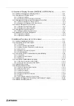
Summary of Contents for F930GOT-BWD-E

Page 1: ...USER S MANUAL F930GOT BWD E ...

Page 2: ... and understood If in doubt at any stage of the installation of the communication facilities of F930GOT always consult a professional electrical engineer who is qualified and trained to the local and national standards which apply to the installation site If in doubt about the operation or use of the communication facilities of F930GOT please consult the nearest Mitsubisi Electric distributor This...

Page 3: ...i GRAPHIC OPERATION TERMINAL F930GOT USER S MANUAL Manual number JY992D86101 Manual revision A Date December 1999 Graphic Operation Terminal F930GOT ...

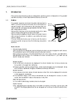
Page 4: ...Graphic Operation Terminal F930GOT ii ...

Page 5: ...7 278 695 Please tick the box of your choice What condition did the manual arrive in Good Minor damage Unusable Will you be using a folder to store the manual Yes No What do you think to the manual presentation Tidy Un friendly Are the explanations understandable Yes Not too bad Unusable Which explanation was most difficult to understand Are there any diagrams which are not clear Yes No If so whic...

Page 6: ...Graphic Operation Terminal F930GOT iv ...

Page 7: ...erators of the completed equipment should be trained to use that product in a safe and coordinated manner in compliance to established safety practices The operators should also be familiar with documentation which is connected with the actual operation of the completed equipment Note Note the term completed equipment refers to a third party constructed device which contains or uses the product as...

Page 8: ...ipment All examples and diagrams shown in this manual are intended only as an aid to understand ing the text not to guarantee operation Mitsubishi Electric will accept no responsibility for actual use of the product based on these illustrative examples Owing to the very great variety in possible application of this equipment you must satisfy yourself as to its suitability for your specific applica...

Page 9: ...ction of SYSMAC C Series 1 20 1 11 Connection of FLEX PC N Series 1 23 1 12 Connection by general purpose communication 1 27 2 Start up 2 1 2 1 Start up procedure 2 1 2 2 Operation environment setting 2 2 2 3 Each mode selection procedure 2 7 2 4 Security function screen protection function 2 8 3 Screen Mode 3 1 3 1 Outline of screen mode 3 1 3 2 Change of displayed data 3 3 3 2 1 Common contents ...

Page 10: ... 3 8 1 2 Common functions 8 4 8 1 3 Functions dedicated to screen creation software for GOT A900 8 7 8 2 Transfer of screen data 8 8 8 3 Use of data in FX 25DU 30DU B E 8 10 8 4 Concept on screen display 8 11 8 4 1 Screen display position 8 11 8 4 2 Number of display screens and screen Nos 8 11 8 4 3 Number of display elements and data capacity 8 12 8 4 4 Attribute of display element 8 13 8 5 Scre...

Page 11: ...23 9 4 6 Proportional Pie Graph 9 24 9 4 7 Panel Meter 9 25 9 4 8 Indicator 9 26 9 4 9 Label Indicator 9 27 9 4 10 Text Indicator 9 28 9 4 11 Image Indicator 9 29 9 4 12 Overlay Screen 9 30 9 4 13 Library Image 9 31 9 4 14 Trend Graph Sampling 9 32 9 4 15 Trend Graph Total 9 35 9 4 16 Ascii 9 37 9 5 Data transfer objects 9 40 9 5 1 Touch Key 9 41 9 5 2 Switch 9 45 9 5 3 Send Data Bank recipe funct...

Page 12: ...y function 11 3 11 3 Data display function 11 4 11 3 1 Display of numerics 11 4 11 3 2 ASCII code display function 11 6 11 3 3 Clock display function 11 9 11 3 4 Comment display function 11 10 11 3 5 Alarm history display function 11 11 11 3 6 Alarm list display function 11 13 11 3 7 Part display function 11 15 11 3 8 Lamp display function 11 16 11 3 9 Panel meter display function 11 17 11 4 Graph...

Page 13: ...functions 13 1 13 2 Connection of bar code reader 13 2 13 2 1 Connection 13 2 13 2 2 Communication specifications 13 2 13 2 3 Setting of system information control devices 13 3 13 2 4 Write to PLC 13 4 13 2 5 Example of sequence program 13 6 13 2 6 Troubleshooting 13 7 13 3 Connection of PLC manufactured by Allen Bradley 13 8 13 3 1 Connection 13 8 13 3 2 Setting of communication 13 9 13 3 3 Devic...

Page 14: ...vi ...

Page 15: ...ens can be limited using the security function Both software packages FX PCS DU WIN E V 2 30 or later for DU and SW D5C GOTRE PACK V H or later indicates a numeric not less than 1 for GOT can be used to create user screens Display function 1 Up to 500 user screens can be displayed In screen creation two or more screens can be overlaid or changed over arbitrarily 2 Simple graphics such as straight ...

Page 16: ...rd Other functions Many other functions are built in 1 A real time clock is built in so the current time can be set and displayed 2 The GOT can function as an interface to enable data communication between the PLC and a personal computer in which the relay ladder creation software is running At this time the GOT screen can also be displayed 3 The screen contrast can be adjusted and the buzzer soun...

Page 17: ... in accordance with the ON OFF status of bit devices X Y M S T and C in the PLC 3 8 9 11 Data change function Set values and current values of word devices T C D V and Z in the PLC can be changed in the form of numeric bar graph trend graph and panel meter 3 8 9 11 Switch function The ON OFF status of bit devices X Y M S T and C in the PLC can be controlled in the form of momentary alternate and s...

Page 18: ...s are automatically displayed for monitoring Valid in FX Series PC diagnosis The error information in the PLC can be read and displayed Valid in FX Series Test mode Screen list User screens are displayed in the order of screen No 5 Other mode Time switch A specified bit device can be kept ON for a spec ified period of time 6 Note 2 PC transfer The screen data and the alarm history can be transferr...

Page 19: ...d to PC 4 A floppy disk may be abbreviated to FD A floppy disk drive may be abbreviated to FDD 5 The graphic operation terminal F930 Series may be abbreviated to GOT 6 Devices inside the PLC may be abbreviated to X input Y output M auxiliary relay S state T timer C counter and D data register Output contacts of X Y M S T and C may be called bit devices All of them may be called devices 2 Startup G...

Page 20: ...o be entered the following expres sion may be used 1 4 2 Basic operations The common operations in the GOT are shown below SCREEN MODE HPP MODE 0 to 9 0 2 6 CLR 1 3 7 4 8 5 9 ENT OFF ON SET DEV END DEVICE MONITOR Function display The selected mode or function is displayed here END key This key terminates the displayed function and returns to the previous screen CLR clear key This key cancels the i...

Page 21: ...ith an FX A Series PLC PC connector RS 232C connector D sub 9 pin male This connector links a personal computer having the screen data created using the screen creation software to allow data transfer When the RS 232C connector in the PC is the 9 pin type use a data transfer cable FX 232CAB 1 When the RS 232C connector in the PC is the half pitch 14 pin type use a data transfer cable FX 232CAB 2 T...

Page 22: ... 14 pin type or Data transfer cable F2 232CAB 1 3 m when the RS 232C connector in the PC is 25 pin type Disabled during computer link RS 232C communication Data transfer cable F2 232CAB 1 3 m General purpose personal computer screen creation software Peripheral units of GOT Printer Dedicated printers GT 10A K6PR K A7 N PR General purpose printers ESC P Printer equipped with RS 232C interface Print...

Page 23: ... FX 422CAB0 Connection cable FX 40DU CAB 3 m or Connection cable FX 40DU CAB 10M 10 m Program cable FX 20P CAB 1 5 m Programmable controller Two port interface FX 2PIF When the two port interface FX 2PIF is used Data transfer cable AC30R4 3 m When the two port interface function is used the operation environment should be set for it Refer to the description on SERIAL PORT on the SET UP MODE screen...

Page 24: ...PHP A7HGP A6GPP A6PHP Handy programming panel FX 10P 20P A Series cannot be used 1 2 3 A general purpose personal computer can be directly connected and both the GOT and the personal computer can be used at the same time without using the FX 2PIF The FX2N FX2NC Series can be used in the instruction device range of the FX2 Series ž ž ž ...

Page 25: ...X 232CAB 2 Transfer cable F2 232CAB 1 F930GOT Personal computer FX 232CAB 1 FX 232CAB 2 or F2 232CAB 1 PC side D sub female 9 pin GOT side D sub female 9 pin 1 2 3 4 5 6 7 8 9 1 2 3 4 5 6 7 8 9 PC side Half pitch 14 pin 7 1 14 8 1 GOT side D sub female 9 pin 1 2 3 4 5 6 7 8 9 1 14 12 13 D sub male 25 pin PC side 13 12 11 10 9 8 7 6 5 4 3 2 1 25 24 23 22 21 20 19 18 17 16 15 14 GOT side D sub femal...

Page 26: ...X FX2C FX0 FX0S FX0N FX2N FX2NC Series manufactured by MITSUBISHI CPU direct CPU PORT MELSEC A Series manufactured by MITSUBISHI CPU direct CPU PORT or computer link LINK PORT SYSMAC C Series manufactured by OMRON Computer link LINK PORT FLEX PC N Series manufactured by FUJI ELECTRIC PLC manufactured by Allen Bradely Co Inc Described in Paragraph 13 3 PLC manufactured by Siemens AG To be available...

Page 27: ...s FX2N when FX2N 232 BD is used CPU PORT RS232C In 1 N connection select CPU PORT RS422 for the second and fourth GOTs AnN AnA AnS AnSJ AnSH A1SJH A2C A2CJ A0J2H AnU AnUS A2USH A1FXCPU CPU PORT RS422 In 1 N connection select CPU PORT RS232C for the second and fourth GOTs Motion controller A171SCPU S3 A171SHCPU A172SHCPU A272UHCPU CPU PORT RS422 In 1 N connection select CPU PORT RS232C for the seco...

Page 28: ...ons Connection cables FX 40DU CAB 10M 20M 30M and FX 50DU CABL Connection cable FX 50DU CAB0 1M 10M 20M 30M D sub male 25 pin PLC side 13 GOT side D sub male 9 pin 12 11 10 9 8 7 6 5 4 3 2 1 25 24 23 22 21 20 19 18 17 16 15 14 5 4 3 2 1 9 8 7 6 15 21 16 17 18 MINI DIN male 8 pin PLC side GOT side D sub male 9 pin 1 2 3 4 5 6 7 8 5 4 3 2 1 9 8 7 6 ...

Page 29: ...y user Refer to the connection diagram 4th GOT FX 232CAB 1 3 m Communication speed The communication speed baud rate with the PLC becomes slower as the number of GOTs increases When the communication speed in the first GOT is supposed as 1 2nd GOT Communication speed in the 1st GOT 2 1 2 of that in the 1st GOT 3rd GOT Communication speed in the 2nd GOT 2 1 4 of that in the 1st GOT 4th GOT Communic...

Page 30: ...diagram 3rd GOT FX 232CAB 1 4th GOT Cable created by user Refer to the connection diagram Communication speed The communication speed baud rate with the PLC becomes slower as the number of GOTs increases When the communication speed in the first GOT is supposed as 1 2nd GOT Communication speed in the 1st GOT 2 1 2 of that in the 1st GOT 3rd GOT Communication speed in the 2nd GOT 2 1 4 of that in t...

Page 31: ...er link unit PLC as shown below In communication via RS 422 In communication via RS 232C Connection cable F2 232CAB is also available Refer to the figure on the right for connection diagram To computer link unit Programming connector is not used RS422 RS232C Terminal block Computer link unit side PLC side GOT side D sub male 9 pin 5 4 3 2 1 9 8 7 6 RDA RDB SDB SG SDA D sub 25 pin FG SD RD RS CS DS...

Page 32: ...Operation Terminal F930GOT Introduction 1 1 18 In communication via RS 232C CD RD SD DTR SG DSR RS CS 5 4 3 2 1 9 8 7 6 D sub 9 pin Computer link unit side PLC side GOT side D sub female 9 pin 1 2 3 4 5 6 7 8 9 ...

Page 33: ...functions of the GOT are disabled Index registers V and Z cannot be monitored and their current values cannot be changed When the RS 232C is connected for communication the printer output function of the GOT is disabled The two port interface function is disabled Table 1 4 Used port When RS 422 is used When RS 232C is used Mode setting switch No 5 RS 422 Format 1 RS 232C No procedure 1 RS 422 No p...

Page 34: ...the manual of each C Series link unit In communication via RS 422 Example of connection with the C200H LK202 V1 In communication via RS 232C Example of connection with the C200H LK201 V1 In communication via RS 232C Example of connection with the CQM1 with built in RS 232C port To host link unit RS422 RS232C GOT side D sub male 9 pin Host link unit side C200H side D sub male 9 pin RDB RDA SDB SDA ...

Page 35: ...is used When RS 232C is used Transmission speed 19200 bps Data bit 7 bits Stop bit 2 bit Parity bit Even Communication mode Host link mode Command level Level 1 2 or 3 Procedure 1 N procedure Unit No 00 to 15 BCD in accordance with setting in GOT The GOT station No can be set in SET UP MODE Refer to Paragraph 2 2 Table 1 6 Set item Set item Remarks Standard communication con dition RS 232C DN6645 ...

Page 36: ...y set to ON OFF is changed Forced ON Data 1 is specified The specified bit is set to ON Forced OFF Data 0 is specified The specified bit is set to OFF Restriction in functions When a host link unit is connected the following GOT functions are disabled or restricted Because the GOT switch function which sets a bit to ON OFF uses a host link com mand FK command which sets resets multi points forcedl...

Page 37: ...plicable PLC and link unit FLEX PC N Series A link unit general purpose RS 232C RS 485 interface module is required to be attached Or a CPU with built in RS 232C interface is required System configuration Link unit NB Series NB RS1 AC NB RS1 DC NJ Series NJ RS2 NJ RS4 NS Series NS RS1 CPU with built in RS 232C interface NJ CPU B16 Select either one by the environment set ting or the software to cr...

Page 38: ...terface GOT side D sub male 9 pin Link unit side PLC side Terminal block SG 5 4 3 2 1 9 8 7 6 RDA RDB SDA SDB D sub male 25 pin GOT side Link unit side PLC side D sub female 9 pin FG SD RD RS CS SG DSR DTR 13 12 11 10 9 8 7 6 5 4 3 2 1 25 24 23 22 21 20 19 18 17 16 15 14 5 4 3 2 1 6 7 8 9 20 8 PLC side D sub male 15 pin RD SD RS CS SG 7 6 5 4 3 2 1 15 14 13 12 11 10 9 GOT side D sub female 9 pin 5...

Page 39: ...mmand Start stop synchroniza tion non procedure Transmission speed 19 200 bps Data bit 7 bits JIS 8 bits HEX Parity bit Even Odd Station No 00 to 15 in accordance with setting in GOT Table 1 12 Set item Description Remarks Mode MODE SW 3 Set by command start stop synchro nization No procedure Station No Station No setting switch 10 1 Upper digit 1 1 Lower digit Table 1 13 Set item Description Rema...

Page 40: ...unication speed 19 200 bps Stop bit 1 bit Character length 8 bits Parity Odd When connecting the FLEX PC have in mind the following restrictions The set values of timers T and counters C cannot be monitored nor changed When the RS 232C is connected for communication the printer output function of the GOT is disabled ...

Page 41: ...screen and specifies actions to be performed by pressing of touch keys The GOT is equipped with the function to display the word data in the form of numerics and bar graphs the function to access the data for changing the status of the bit data using switches etc The target of access at this time is the data area inside the GOT The data location to be accessed is specified by the screen data Accor...

Page 42: ...the software To use general purpose communication select SET UP MODE PLC TYPE and UNI VERSAL in this order in the GOT main body To set the communication speed baud rate the data length the stop bit length and the parity select SET UP MODE and SERIAL PORT RS 232C in this order in the GOT main body Set each parameter to an either available value shown below Table 1 15 Baud rate 19 200 9 600 4 800 2 ...

Page 43: ... case immediately after sending a response the GOT sends an interrupt code The GOT may send an interrupt code while receiving a command When an event such as change in the ON OFF status of a specific bit and screen changeover has occurred the GOT sends an interrupt code The table below shows the correspondence between the interrupt code and the event type Table 1 16 Event type Interrupt code hexad...

Page 44: ...f addition excluding STX is converted into an ASCII code and sent The sum consists of the upper digit and the lower digit in this order When a command is Type 2 a response to it will be Type 2 or Type 3 Type 3 This type of format consists of only one character This format is used for responses ACK or NAK and interrupt codes The table below shows characters available in statements Interrupt codes i...

Page 45: ...should be specified in the order of upper digit and lower digit in ASCII codes For example enter 8 A to specify 8AH bytes 138 bytes Data The data stored in the specified address is stored in turn One byte data is converted into ASCII codes and sorted in the order of upper digit and lower digit CR Size STX Read address 0 Type 2 may be used Command CR STX žžžžžžžžžžžžžžžžžžžžžžžžžžžžžžžžž Data 1 Res...

Page 46: ...ASCII codes Data Sort the write data in the ascending order of address Convert one byte data into ASCII codes and sort it in the order of upper digit and lower digit The maximum allowable number of data is 255 510 after converted into ASCII codes CR Size STX Write address 1 Type 2 may be used Command Data 1 Data 2 ACK Response Example When 2 byte data is written to the address 120H format Type 2 S...

Page 47: ...es and a serial No from 0 to 4 095 is assigned to each of them Each word data is stored in the order of upper side and lower side In the case of a double word 32 bit data data is stored from the higher address to the lower address Bit data There are 2 048 bit devices and a serial number from 0 to 2 047 is assigned to each of them Each address stores 8 bit data 0000 0001 0002 0003 1FFE 1FFF žžž D0 ...

Page 48: ...0 2201 2202 b7 b6 b5 b4 b2 b3 b0 b1 2203 2204 2205 2206 2207 M8007 M8006 M8005 M8004 M8002 M8003 M8000 M8001 M8015 M8014 M8013 M8012 M8010 M8011 M8008 M8009 M8023 M8022 M8021 M8020 M8018 M8019 M8016 M8017 M8031 M8030 M8029 M8028 M8026 M8027 M8024 M8025 M8039 M8038 M8037 M8036 M8034 M8035 M8032 M8033 M8047 M8046 M8045 M8044 M8042 M8043 M8040 M8041 M8055 M8054 M8053 M8052 M8050 M8051 M8048 M8049 M80...

Page 49: ... GOT does not output interrupt codes M8050 1 second cycle clock M8051 2 second cycle clock M8052 to M8063 Unused D8000 D8001 32 bit counter of 100 ms The time after the power is turned on is counted in the units of 100 ms The lower word is stored in D8000 The upper word is stored in D8001 D8002 Contents of communication error This device indicates the contents of an error occurred in communication...

Page 50: ... 1020 OPEN COM1 AS 1 1030 SENDDATA 100140479183CF0 Send statement 1040 PRINT 1 STX SENDDATA CR 1100 REC0 Receive of first character 1110 RVCNT 1 1120 GOSUB JYUSHIN 1130 IF ERFLG 99 THEN GOTO ERRORFIN1 1140 BUF RCV 1150 HED LEFT BUF 1 1160 IF HED ACK THEN GOTO FIN 1170 ERRORFIN1 1180 PRINT Error code is sent back 1190 GOTO FIN 1700 ERRORFIN1 1710 PRINT No response 2000 FIN 2010 CLOSE 1 2020 END 210...

Page 51: ...urned on while the upper left corner which functions as a touch key of the screen of the GOT is pressed and held for 1 second or more the SET UP MODE screen is displayed Ÿ The OPENING SCREEN screen indicating the model name the version etc is displayed for the period of time set in OPENING SCREEN on the SET UP MODE screen Ÿ Ÿ On the SET UP MODE screen set the used mode the connected PLC name etc T...

Page 52: ...s connected to the GOT or when communication is per formed between the GOT and a micro computer board 4 OPENING SCREEN Allows to set the duration in which the OPENING SCREEN screen is displayed immediately after the power is turned on 5 MAIN MENU CALL KEY Allows to set the position of the touch key which calls the SELECT MODE screen from the screen mode in which user screens are displayed 6 SET CL...

Page 53: ...tems 1 to 5 7 and 8 are set in the GOT and the screen data created using the screen creation software is transferred the operation environment setting selected in the screen creation software becomes valid In such a case set the operation environment in the GOT again or align from the beginning the setting of the items 1 to 5 7 and 8 above with that in the screen creation software ...

Page 54: ...ector in the PLC RS 422 or RS 232C The FX Series the A Series a motion controller and the N Series are available LINK PORT RS 422 The GOT performs communication in accordance with RS 422 via a link unit The A Series the C Series and the N Series are available LINK PORT RS 232C The GOT performs communication in accordance with RS 232C via a link unit The A Series the C Series and the N Series are a...

Page 55: ...to 0 the screen mode is selected immediately after the power is turned on and a user screen is displayed It is recommended to set 1 second or more for the FX Series and 4 seconds or more for the A Series Set the menu call key which changes over the screen mode in which a user screen is dis played to the SELECT MODE screen The menu call key is mesh type and 2 2 in size One or two corners can be sel...

Page 56: ...d press the ENT key to register it The service life of the backlight is 50 000 hours The specified bit of the control device system information should be set to ON so that the backlight OFF function is enabled Refer to Paragraph 8 6 Set whether or not the buzzer is to sound when a key is pressed or an error occurs Select BUZZER ON or BUZZER OFF The LCD brightness can be set in 15 steps When the ke...

Page 57: ...ELECT MODE screen shown on the left is displayed The outline of each mode and the selection procedure are described below USER SCREEN MODE Refer to Sections 3 8 9 10 11 and 12 A user screen is displayed Char acters such as alphabets num bers Katakana and Hiragana and simple graphic can be displayed HPP MODE Refer to Section 4 Bit devices and word devices in the PLC can be monitored In addition set...

Page 58: ...d entry code 2 Input of entry code To enter an entry code the entry code input screen should be displayed To display the entry code input screen a touch key should be provided on the screen When a screen whose entry code level is higher is tried to be displayed an alarm sound is issued three times Set a touch key and enter an entry code When an entry code has been registered to the screen to be di...

Page 59: ... Screen 1 is displayed ini tial status In the use example shown above the levels and the screen Nos are consecutive for easy understanding The levels and the screen Nos are not necessarily consecutive Example Screen 1 Level 3 Screen 2 Level 7 Screen 3 Level 5 Screen 10 Level 2 The system screens screen Nos 1000 and later are treated as Level 15 Screen example Reset of entry code Touch key To set t...

Page 60: ...Graphic Operation Terminal F930GOT Start up 2 2 10 MEMO ...

Page 61: ...racters straight lines rectangles circles etc which are classified in accordance with their functions are combined and displayed When there are two or more user screens they can be changed over using the operation keys in the GOT or using the PLC The user can set arbitrarily the condition to change over the screens and the screen to be displayed next On one screen the following elements can be dis...

Page 62: ...s circles etc This function monitors the contents of devices in the PLC in the specified size in the specified position The specified area can be inverted by turning ON OFF bit devices in the PLC Numerics bar graphs indicators etc 1 The information inside the PLC is monitored Data is transferred to the PLC This function turns ON OFF specified devices in the PLC and overwrites the data when a speci...

Page 63: ...9 ENT CLR When the keyboard is always displayed OPERATION STATE MONITOR CURRENT VALUE 1 2 3 4 5 6 7 8 Cursor display 0 2 6 CLR 1 3 7 4 8 5 9 ENT CURRENT VALUE 1 2 3 4 1 2 3 4 Cursor display When the keyboard is called When a numeric or an ASCII code dis played on the screen is touched the cur sor is displayed and the numeric or the ASCII code can be changed using the dis played keyboard When the S...

Page 64: ... entered using ASCII codes make sure that the keyboard to input Katakana characters and alphabets is always displayed on the screen When the keyboard is used in the SWoD5C GOTRE PACK the keyboard should be created using the key codes for touch keys When the keyboard is called only 0 to 9 can be entered ...

Page 65: ...ile registers cannot be changed b When an EEPROM memory is mounted in the FX Series PLC or while the FX A Series PLC is running set values of timers and counters and current values of file registers can not be changed c When an entry code is registered in the FX A Series PLC set values of timers and counters and current values of file registers cannot be changed Reset the entry code n n n nImporta...

Page 66: ...t value of a word device is changed using the following objects the flag becomes ON Object names Data Change and Keyboard The flag does not become ON when the Data 1 Data 1 or Constant object is used ON timing The flag becomes ON when the ENT key of the Data Change or Key board object is pressed The flag does not become ON when any other key is pressed While the touch key code is set to 000D Write...

Page 67: ...ENT key is pressed on the ten key win dow the flag becomes ON While the touch key code is set to 000D the flag becomes ON when the touch key is pressed Once the completion flag becomes ON it remains ON To set it to OFF execute the RST reset instruction in a sequence program 2 User ID The user ID can be assigned to each Numerical Input and Ascii Input using the screen creation software The user can...

Page 68: ...Graphic Operation Terminal F930GOT Screen Mode 3 3 8 MEMO ...

Page 69: ...isplayed Paragraph 2 3 Select HPP MODE on the screen The screen shown below is displayed END HPP MODE HPP MODE MENU DEVICE MONITOR ACTIVE STATE MONITOR PC DIAGNOSIS 1 3 2 Among the following functions 2 and 3 are valid only when the FX Series PLC is connected 1 DEVICE MONITOR Paragraph 4 2 The ON OFF status and the set value current value of arbitrary devices in the PLC can be monitored In additio...

Page 70: ...MONITOR is selected on the HPP MODE screen the DEVICE MONITOR screen shown on the left is displayed Function keys are provided at the bottom of the screen Each function key is actuated when touched DEVICE Allows to specify the device No to be monitored ON OFF Turns ON OFF forcedly the specified device SET Executes change of the current value set value The HPP MODE screen is displayed DEVICE Enter ...

Page 71: ...er counter when monitoring is per formed When the set value is changed as described in the next page the contents of the data register are overwritten ON status The ON OFF status of each monitored device is indicated as follows OFF status The HPP MODE screen is displayed DEVICE MONITOR Select DEVICE MONITOR on the screen DEVICE Enter a device symbol X X ENT Select X0 0 Display X0 on the screen DEV...

Page 72: ...s used as the memory in the PLC They cannot be changed when an EPROM or EEPROM cassette is used T C D monitor display Move the cursor to a device to be changed SET Change the set value of T and C Change the current value of D T and C 1 Enter the minus sign 0 to 9 Enter a numeric ENT Execute change 1 When the SET key is pressed the numeric input keyboard is displayed Numeric decimal input keyboard ...

Page 73: ...ue of D0 SET 2 0 0 ENT Register 200 as new value Paragraph 4 1 Fig 1 Before change SET ON OFF DEV END DEVICE MONITOR CUR 300 D 0 Fig 2 After change SET ON OFF DEV END DEVICE MONITOR CUR 200 D 0 Monitor of T1 DEVICE Enter element symbol T T 1 ENT Display the T1 monitor Refer to Fig 1 Change of the current value of T1 Start change of the current value of T1 SET 3 0 0 Execute change to 300 from 263 E...

Page 74: ...ON OFF of output Y0 and auxiliary relay M0 Y M S T C D V Z monitor display Move the cursor to a device to be forcedly set to ON OFF ON OFF ON OFF Paragraph 4 1 Display Y0 M0 monitor using the procedure described in Paragraph 4 2 1 ON OFF ON Display the ON screen 1 OFF ON ON Display the ON screen 2 Move the cursor to M0 Move the cursor to Y0 OFF OFF Move the cursor to M0 Screen 1 SET ON OFF DEV END...

Page 75: ... step ladder monitor valid is not ON in the sequence program the message M8047 IS NOT ON is displayed When there are more than eight state Nos in the ON status eight Nos are displayed from the smallest one in the ascending order Excessive state Nos are not displayed ACTIVE STATE MONITOR END ACTIVE STATE MONITOR S 100 S 200 S 300 S 400 S 500 S 600 S 800 S 900 1 The HPP MODE screen is displayed ACTI...

Page 76: ...Program errors Parallel link errors Operation errors When there are no errors in the PLC the message NO PLC ERROR is displayed When there are errors the following display is given When errors in the PLC are reset the message NO PLC ERROR is automatically dis played For the contents of errors refer to the instruction manual of the PLC main body The HPP MODE screen is displayed PC DIAGNOSIS Select P...

Page 77: ... u u uBasic operation The SELECT MODE screen is displayed The TEST MODE screen is displayed TEST MODE Paragraph 2 3 Select TEST MODE on the screen The screen shown below is displayed TEST MODE END TEST MODE USERSCREEN 1 1 USER SCREEN The list of user screens displayed in the screen mode can be displayed Graphic Operation Terminal F930GOT ...

Page 78: ...using the screen creation software Scroll the display by one line The TEST MODE screen is displayed The screen list is displayed USER SCREEN Paragraph 5 1 Select USER SCREEN on the screen The screen shown below is displayed Common setting screen Displays the screens written in the common setting in the screen creation software when the FX PCS DU WIN E is used When an area indicating a screen No an...

Page 79: ...IME SWITCH OTHER MODE SET UP MODE 1 2 3 4 5 In the other mode the following functions are offered 1 SET TIME SWITCH Turns on the specified bit device during the specified period of time This function is valid when the screen creation software FX PCS DU WIN E is used 2 DATA TRANSFER Transfers user screens and the alarm history between the screen creation software 3 PRINT OUT Prints out the alarm hi...

Page 80: ...e ON The devices will remain ON from the start time to the end time on the selected days of the week END TIME If the end time is earlier than the start time the specified bit devices remain ON until the follow ing day even if the day of the week of the following day is not selected 1 Target bit device Specify up to 8 consecutive bit devices In the setting on Screen 2 CH1 M100 will remain ON from 1...

Page 81: ...ansferred from a personal computer to the GOT the following screen is displayed also without regard to the screen displayed at that time And when data transfer is finished the screen No 0 is displayed if the DU WIN E is used or the screen No 1 is displayed if the screen creation software for the GOT A900is used The OTHER MODE screen is displayed The DATA TRANSFER screen is displayed DATA TRANSFER ...

Page 82: ...ect a printer Perform the printout operation in the GOT Select the printout data and execute printout procedure shown below Connect a printer to the GOT and power them up Manipulate the GOT and select PRINT OUT on the OTHER MODE screen Select the data to be printed out The alarm history can be printed Printer output setting The screen shown below is displayed ALARM HISTORY Select ALARM HISTORY on ...

Page 83: ...K Unlocks temporarily the existing entry code The entry code is kept registered in the PLC The unlock function is valid until the power of the GOT is turned off Note When you have forgotten the existing entry code execute all clear in a peripheral unit However have in mind that all of the data including programs in the PLC are deleted by all clear It is recommended not to forget the entry code u u...

Page 84: ...lish used on the system screens 2 PLC TYPE Allows to set the connected PLC type 3 SERIAL PORT To be set when a printer is connected to the GOT or when communication is performed with a micro computer board 4 OPENING SCREEN Allows to set the duration in which the open ing screen is displayed immediately after the power of the GOT is turned on 5 MAIN MENU CALL KEY Allows to set the positions of the ...

Page 85: ...56 consecutive bit devices X Y M S T and C in the PLC which have been preliminarily specified as alarm devices Alarm devices can be assigned and alarm messages comments can be created using the screen creation software When the FX PCS DU WIN E is used Alarm devices Can be set in Alarms in View Alarm messages Can be created in Alarms in View When the SWo5DC GOTRE PACK is used Alarm devices Can be s...

Page 86: ...creation software Check the table below In the screen mode while a user screen is displayed Printing by printer is available except for the data transferred from the screen creation software Note 1 Displayed when the DETAIL key is pressed on the system screen Table 7 1 Notification method FX PCS DU WIN SWo o o oD5C GOTRE PACK Window display comment window display ü Either one can be selected ü Not...

Page 87: ...en mode again In the case of SWoD5C GOTRE PACK By setting Detail Display Destination in Basic Setting in Alarm History Common Setting in the software to Comment Window detailed comment messages corresponding to alarm devices can be displayed In this case the object Alarm History or Alarm List is displayed on the user screen and detailed comment messages are displayed when a touch key whose key cod...

Page 88: ...e date of occurrence and a corresponding alarm message can be printed Alarm messages should have been entered in half width characters The communication condition of the used printer should have been set in SERIAL PORT in SET UP MODE in the GOT 4 Flow display valid when the SWoD5C GOTRE PACK is used When an alarm device becomes ON a corresponding alarm message is displayed at the bottom of the use...

Page 89: ...he alarm history and the alarm frequency up to the following number of cases can be stored respectively They are stored even if the power is turned off Alarm history Up to 1 000 cases If 1 001 or more alarms have occurred the record is updated while excessive alarms are deleted from the oldest one When the SWoD5C GOTRE PACK is used it can be set so that excessive alarms are deleted from the latest...

Page 90: ...d When the first bit b0 of a control device becomes ON the alarm history is cleared When the screen creation software for GOT A900 SWoD5C GOTRE PACK is used When the first bit b0 of the head read device word device becomes ON the alarm his tory is cleared By using a device specified in History Clear Trigger in Alarm History Common Setting in the screen creation software the alarm history can be cl...

Page 91: ...han 1 compatible with the Windows95 and the WindowsNT a Data can be read from and written to the F930GOT using the screen creation software for DU b Data can be read from and written to the F930GOT using the screen creation software for GOT A900 This section describes the compatibility of data when these screen creation software are used For the operating procedures for the software refer to the s...

Page 92: ...ftware for GOT A900 However some function names are different and some functions are restricted in each software Refer to 8 1 2 Common functions c Functions dedicated to the screen creation software for GOT A900 Refer to Paragraph 8 1 3 These functions are supported by only the screen creation software for GOT A900 They are not supported by the F930GOT nor the screen creation software for DU Scree...

Page 93: ...his is the device monitor function in the HPP mode explained in Section 4 By using this function comments can be displayed instead of device Nos nImportant point Note When the functions 1 to 4 above are used they are treated as follows in the screen creation software for GOT A900 Read of data to the software for GOT A900 The screen data excluding the functions 1 to 4 above is read Even when the da...

Page 94: ...ing is permitted Ascii Display ßWhen setting is forbidden Ascii Ascii Input ßWhen setting is permitted Comment In case of word deviceà Library Text In case of bit deviceà Text Indicator Part Display In case of word deviceà Library Image In case of bit deviceà Image Indicator Lamp Label Indicator Panelmeter Shape displayed on screen is different Panel Meter Circle Graph Clock Japanese is not availa...

Page 95: ...peration bit momentary Names are different Switch momentary bit ALT Switch alternate bit SET Switch set bit RST Switch reset Base changeover ßBit condition etc cannot be converted Change Screen Word operation Indirect Fixed value Names are different Increment Indirect Fixed value Decrement Fixed value Write Constant Name in screen creation software for GOT A900 Difference in set item attribute Nam...

Page 96: ...arithmetic operation can be per formed only while the gains and the offset are specified that is while the arithmetic operation formula is fixed Display trigger Only Always is available as the display trigger except in some objects In line graphs the display trigger is used to specify the sampling cycle Range specification The color and the blink attribute cannot be changed over by a value of a wo...

Page 97: ...ers In the F930GOT the scale function is given to bar graphs and meters Paint Paints fills a specified area which may be a polygon In the F930GOT boxes and circles can be filled Data List Displays the data list in the form of table Level Displays the level within a specified image range In the F930GOT the level can be expressed in the form of bar graph box Part Movement Moves displayed parts on a ...

Page 98: ...er to Para graph 8 1 1 a Software for DU No problems are expected in both read and write b Software for GOT A900 If the F930GOT has dedicated functions such functions are not read Setting of display screen changeover Refer to Paragraph 8 1 2 c Software for DU Names and contents of the functions are automatically converted into those used in the software d Software for GOT A900 Names and contents o...

Page 99: ... converted screen No is transferred to the F930GOT Accordingly the used sequence program is required to be changed Handling of common setting screen The contents set on the common setting screen in the screen creation software for DU are treated as the screen No 501 in the screen creation software for GOT A900 However the screen No 501 is treated as a user screen so the contents of the screen No 5...

Page 100: ...age Indicator When a black and white image is selected as an image to be used using the functions above the image can be displayed in colors other than black and white in the 25DU 30DU by specifying the colors In the F930GOT the same operation can be performed using the Indicator function b Number and Ascii Only numerics and character codes can be changed on the display screen Data can be changed ...

Page 101: ...is used Refer to Section 10 When the screen creation software for GOT A900 is used Refer to Section 12 8 4 1 Screen display position The screen size is shown below The display position can be specified in the unit of dot 8 4 2 Number of display screens and screen Nos Up to 500 screens can be displayed A screen No is assigned to each display screen When the screen creation software for DU is used N...

Page 102: ...he allowable number of screens and capacity are restricted as shown below Item Description Total screen data size 256 KB including user screens external characters etc Number of displayable screens User screens Up to 500 screens FX PCS DU WIN E Nos 0 to 499 SW D5C GOTRE PACK Nos 1 to 500 System screens 16 screens Nos 1001 to 1030 Data size per screen Up to 16 000 byte ...

Page 103: ...E Display color background color needle color and frame color SW D5C GOTRE PACK Character color plate color and frame color Screen background color FX PCS DU WIN E Eight colors or two colors black and white can be specified SW D5C GOTRE PACK Only black can be specified Device specification specification of devices in the PLC Word device Timer T counter C data register D and index register V and Z ...

Page 104: ...wo other screens can be overlaid at a time When this overlay function is used together with the screen call function the screen call function is effective only for the base screen The screen call function is not effective for the second and third screens to be overlaid If the screen call function is used for the second and third screens the base screen selected in the screen call function is overl...

Page 105: ...he screen call function is used the common setting screen the base screen and up to four other screens that is up to 6 screens in total can be overlaid Display example 1 SW D5C GOTRE PACK for GOT A900 When this software is used 500 user screens Nos 1 to 500 can be overlaid When the screen call function is used the base screen and up to five other screens that is up to 6 screens in total can be ove...

Page 106: ...In the FX PCS DU WIN E three screens can be overlaid even if the Overlay Screen object is used In this case however the overlay function described here is not available F930GOT FX PCS DU WIN Sequence program D0 Specifies the screen No of the screen to be displayed as the first one D1 Specifies the screen No of the screen to be displayed as the second one D2 Specifies the screen No of the screen to...

Page 107: ...erlay Only the screen specified by the control word device D0 is displayed b Overlay of two screens Two screens specified by the control word devices D0 and D1 are displayed Or two screen specified by the control word devices D0 and D2 can be displayed c Overlay of three screens Three screens specified by the control word devices D0 D1 and D2 are displayed D 0 D 1 D 2 Screen No 1 1 Base screen Scr...

Page 108: ...plays the screen No 1 Stores 1 in control devices indicating screens not to be overlaid Counts the number of bolts Specify the screens to be overlaid Screen No 10 D1 Screen No 20 D2 Resets the counter by X4 when supplement is completed Base screen to be overlaid Specify the screens to be overlaid Screen No 11 D1 Screens overlay is not performed Screen overlay is finished Stores 1 in control device...

Page 109: ... Display screen realized by overlay No 1 No 11 LINE 1 DRIVING MATERIAL REPLENISHMENT COMPLETION Touch key No 0 MENU Touch key No 0 1 2 Control Input Touch key No 0 Touch key No 0 Bit Device X0 X1 Control Input Bit Device Touch key No 0 Not effective PC Not effective Touch key No 0 Not effective PC Not effective Touch key No 0 Not effective 0 Not effective Screen currently being created After the s...

Page 110: ... and the overlap window 2 can be specified using arbitrary word devices The word devices may not be consecutive When overlay is not performed enter 0 to the specified devices or perform setting so that overlap windows are not used The screen Nos currently displayed can be checked using Write Device in System Infor mation in the screen creation software Refer to Paragraph 8 6 Write devices Head wor...

Page 111: ...creen 2 can be over laid c Overlay of three screens Three screens specified by D0 D1 and D21 the base screen the overlap screen 1 and the overlap screen 2 are overlaid Screen No specifying the base screen Base screen A Screen No specifying the base screen Base screen A B Screen No specifying the overlap screen 1 Display screen B A Screen No specifying the base screen Base screen A B Screen No spec...

Page 112: ...n in Common Setting in the SW D5C GOTRE PACK K2 D0 K0 D1 K0 D2 Selects the line 1 Displays the screen No 2 Stores 0 in control devices indicating screens not to be overlaid Counts the number of bolts Specify the screens to be overlaid Screen No 10 D1 Screen No 20 D2 Resets the counter by X4 when supplement is completed Base screen to be overlaid Specify the screens to be overlaid Screen No 11 D1 S...

Page 113: ... 2 is displayed when the START touch key is pressed Set the MENU START touch key so that the screen No 1 is displayed when the MENU START touch key is pressed Overlay of three screens The screens Nos 10 and 20 overlay the screen No 1 In this overlay example the line 1 screen No 2 is adopted Overlay of two screens The screen No 11 overlays the screen No 2 Screen No 10 Screen No 20 BOLT M3 30 LINE 1...

Page 114: ...7 are specified when the GOT is shipped from the factory Details of bit devices Occupied bit devices are used for communication using ON OFF signals When the auxiliary relay M0 is assigned 1 The PLC gives instructions to the GOT Coils are turned on off in programs in the PLC 2 The GOT transmits the information to the PLC Contacts are used in programs in the PLC Auxiliary relay Contents of control ...

Page 115: ... screen is displayed D1 Specifies the screen No of the overlaying screen 1 dis played when two screens are displayed D2 Specifies the screen No of the overlaying screen 2 dis played when three screens are displayed 10 4 2 8 5 D3 D4 D5 These word devices store the screen Nos of the screens cur rently being displayed in the screen mode D3 Stores the screen No of the base screen currently being displ...

Page 116: ...played When screen overlay is not performed 1 is stored Screen Nos of the screens currently displayed are stored in D3 to D5 User screens Nos 0 to 499 and system screens No 1000 and later are available When screen overlay is not performed 1 is stored in D4 and D5 D3 to D5 D6 stores a data file No D7 indicates the ID No of an object M0 M2 M6 becomes ON when the backup battery power of the GOT has d...

Page 117: ...software However write devices not used in the F930GOT can be used as general word devices No devices are set when the F930GOT is shipped from the factory Details of read devices Head of specified word devices Reads the GOT information to its bits 0 to 2 b0 to b2 Head 1 of specified word devices Specifies the recipe No to be read from written to the PLC using the recipe function When the data regi...

Page 118: ...ed in the screen mode D20 Stores the screen No of the base screen currently dis played D21 Stores the screen No of the second screen overlap win dow 1 when two screens are overlaid D22 Stores the screen No of the third screen overlap window 2 when three screens are overlaid 8 5 D23 Stores the ID of an object whose input is completed 3 3 D24 b0 b0 remains ON while a device assigned in the alarm fun...

Page 119: ...s not performed 0 is stored in D21 and D22 D20 to D22 D23 stores the ID No of an object M10 M11 D20 D21 D22 The screen Nos of screens currently displayed are written to them 3 4 5 The ID No of a manipulated object is stored in D23 GOT Sequence program Read devices Write devices Always ON K1M10 D10 MOV D11 K MOV Always ON K1M20 D24 MOV M20 remains ON while an alarm device remains ON M23 become ON w...

Page 120: ...Graphic Operation Terminal F930GOT Creation of Display Screens 8 8 30 ...

Page 121: ...ion Object name Description Use example Text Displays alphabets numerics Katakana Hiragana Kanji JIS level 1 symbols external characters created by the user or sym bols created by the user External characters can be registered using the screen creation software External characters are avail able only in the screen creation software for DU a b Line Displays a line connecting specified two points f ...

Page 122: ...by setting to ON OFF a bit device in the PLC Label Indicator Displays specified characters when a specified bit device becomes ON Text Indicator Displays two types of texts alternately in accordance with the ON OFF status of a bit device in the PLC Texts stored in the text library can be specified for display Image Indicator Displays two types of images alternately in accordance with the ON OFF st...

Page 123: ...read from or writ ten to corresponding data registers Write Con stant When a specified touch key is pressed set data is written to a word device in the PLC Data Setting Allows to change a specified word device in the PLC When a key is pressed the ten key pad is displayed on the screen so that a specified numeric can be changed using this key pad Increment Adds 1 to the data of a specified word dev...

Page 124: ... registered on the screen currently displayed in the screen mode are effective When the display screen is changed over objects registered on the newly displayed screen become effective Available objects All objects The figure below shows the relationship between the setting for all screens and the setting for individual screen nImportant point When an object is registered in the setting for all sc...

Page 125: ...it of dots Bg Text and Bg Transparent Enter the background color and the text color Initial values White and black When Bg Transparent is made effective with a check mark the setting of Bg is not effective Character Size Enter the width W and the height H The available sizes are 0 5 1 2 3 and 4 Shift The text can be shifted to the right the left or the center Text Enter the characters to be displa...

Page 126: ...uDisplay example A line is drawn in solid line Use a line to draw a polygon except square and rectangle Attribute Contents of setting Start Position Enter the X and Y coordinates of the start point of the line in the unit of dot End Position Enter the X and Y coordinates of the end point of the line in the unit of dot Color Enter the display color Initial value Black Example ...

Page 127: ...quare or rectangle is drawn in solid line Use a line to draw a rectangle whose one angle is not 90 or a rectangle whose one edge is not horizontal nor vertical Attribute Contents of setting Start Position Enter the X and Y coordinates of one diagonal point in the unit of dot End Position Enter the X and Y coordinates of the other diagonal point in the unit of dot Color Enter the display color Init...

Page 128: ...to be filled it is recommended to specify the screen color in the header setting in the screen creation software Attribute Contents of setting Start Position Enter the X and Y coordinates of one diagonal point in the unit of dot End Position Enter the X and Y coordinates of the other diagonal point in the unit of dot Frame and Fill Enter the frame color and the filling color Initial values Black a...

Page 129: ...ting u u u uDisplay example A circle is displayed in continuous line Use the Filled Circle object to display a circle whose inside is filled Attribute Contents of setting Position Enter the X and Y coordinates of the center position in the unit of dot Radius Enter the radius in the unit of dot Circle Enter the display color Initial value Black Circle frame color Example ...

Page 130: ...ng Position Enter the X and Y coordinates of the center in the unit of dot Radius Enter the radius in the unit of dot Circle and Fill Enter the circle color and the filling color Initial values Black and white A Circle circle color Fill filling color When the Text or Number object is combined fill the circle at first then create an object to be displayed on it If the Filled Circle object is create...

Page 131: ... displayed in the same size as that of the image stored in the image library Images can be registered to the image library using the screen creation software Attribute Contents of setting Position Enter the X and Y coordinates of the start point in the unit of dot Bg and Fg Enter the background color and the image color Initial values White and black No Enter the image No of an image in the image ...

Page 132: ...glish format 12 00 n n n nImportant point Displayed date and time The date and the time set in the operation environment setting in the GOT main body are displayed Attribute Contents of setting Position Enter the X and Y coordinates in the unit of dot Bg and Text Enter the background color and the text color Initial values White and black Character Size Enter the width W and the height H of charac...

Page 133: ... Contents of setting Position Enter the X and Y coordinates in the unit of dot Bg and Text Enter the background color and the text color Initial values White and black Character Size Enter the width W and the height H of characters The available sizes are 0 5 1 2 3 and 4 Word Device Enter a word device in the PLC which stores a text No to be displayed Enter Data Size and Displayed Value Current or...

Page 134: ...ce LS1 Zero point LS2 Intermediate point LS3 Final point 0 20 21 22 Zero point Intermediate point Finished Text No Library Text Word Device D10 Data Size 16 bits Displayed Value Current Text library MOV LS1 LS2 LS3 MOV MOV K20 K21 K22 D10 D10 D10 Transfers the text No 20 to D10 Transfers the text No 21 to D10 Transfers the text No 22 to D10 STARTING POINT POSITION LINE The display start point is f...

Page 135: ...l leading 0 with without sign Hexadecimal Octal Binary and Real ß3 Shift Select the layout among Right Center and Left ß4 Gain 1 Gain 2 and Offset Monitor value Gain 1 Gain 2 Offset The result of this arithmetic operation is displayed ß5 Data Changeable Set whether or not the data of the specified device can be changed using the keys ß6 Minimum Value and Maximum Value Set the lower limit and the u...

Page 136: ...s A numeric of three digits is displayed 12 3ms The number of in the specified format is regarded as the total number of digits and the number of digit after decimal point is regarded as 0 3 Style Decimal leading 0 Decimal or Hexadecimal When Decimal leading 0 is selected 0 is displayed in upper digits up to the speci fied total number of digits Example When the total number of digits is set to 7 ...

Page 137: ...his attribute is made effective with a check mark data can be changed if the Increment Decrement Data Setting or Keyboard object is combined For the operating procedure refer to Paragraph 3 2 7 Minimum Value and Maximum Value Specify the input range adopted when Data Changeable is made effective 8 User ID Refer to Paragraph 3 3 A serial No is automatically assigned to each registered Number object...

Page 138: ...Graphic Operation Terminal F930GOT Creation of Display Screens FX PCS DU WIN E 9 9 18 u u u uDisplay example LINE 1 LINE 2 HEATING TIME 89 6 s 126 3 s Text object Number object ...

Page 139: ...the bar graph Attribute Contents of setting Position Enter the X and Y coordinates in the unit of dot Size Enter the width W and the height H of the bar graph in the unit of dot The allowable minimum value is 8 W x 16 H Bg and Fg Enter the background color and the display color Initial values White and black Graph Type Select the graph type among Right left à right Up down à up Left right à left a...

Page 140: ... Value 3000 Example D1 1500 D1 0 Minimum Value 1000 Current value of word device 1500 25 Maximum Value 3000 When the value of the word device is smaller than Minimum Value Graph Type Right left right Graph Type Up down up Maximum Value Minimum Value Current value of word device Ticks Ticks à à In the case of Left right à left or Down up à down the Maximum Value position and the Minimum Value posit...

Page 141: ...cks is equivalent Scale Position Up upper edge Scale Position Down lower edge Left Right Graph Type Right left right Graph Type Up down up Up Down Ticks The interval among ticks is equivalent Scale Position Right right edge Scale Position Left left edge à à NUMBER OF PRODUCTION OPERATION RATE PRODUCTION CONTROL 1234 Text object Number object 100 Bar Graph object ...

Page 142: ...and Left Direction Select Clockwise or Counterclockwise ß1 Word Device Enter a word device whose value is to be displayed in the circle graph Enter Data Size and Displayed value Current or Preset also Minimum Value and Maximum Value Enter the minimum value 0 and the maximum value 100 of the data Direct to enter a value directly or Indirect to enter a data register can be selected Ticks Enter the n...

Page 143: ...ß 1 Nbr Of Devices Enter a numeric from 1 to 8 as the number of word devices to be displayed in the proportional bar graph ß 1 Bar 1 Bar 2 Bar 3 Bar 4 Bar 5 Bar 6 Bar 7 Bar 8 and Bar Frame Enter the display color of each data and the bar frame color ß 2 Ticks Enter the number of ticks on the scale attached to the proportional bar graph ß 3 Frame Select the frame displayed around the proportional b...

Page 144: ...nter a numeric from 1 to 8 as the number of word devices to be displayed in the proportional pie graph ß 1 Pie 1 Pie 2 Pie 3 Pie 4 Pie 5 Pie 6 Pie 7 Pie 8 and Circle Enter the display color of each data and the circle frame ß 2 Ticks Enter the number of ticks of the scale attached to the proportional pie graph Frame Select the frame displayed around the proportional pie graph Initial value No fram...

Page 145: ...olor ß 2 Word Device Enter a word device whose value is to be displayed in the form of panel meter Enter Data Size and Displayed value Current or Preset also Minimum Value and Maximum Value Enter the minimum value 0 and the maximum value 100 Direct to enter a direct value or Indirect to enter a data register can be selected Ticks Enter the number of ticks of the scale attached to the panel meter w...

Page 146: ... Position Enter the X and Y coordinates in the unit of dot Size Enter the width W and the height H in the unit of dot Color 1 and Color 2 Enter the colors to be exchanged Initial values Black and white Bit Device Enter a bit device to be referred to positive logic or negative logic When any object is not located within the area specified for the Indicator object When M50 becomes ON a contact the c...

Page 147: ...be specified ß 2 Label Color Enter the color of the text Initial value Black ß 3 Off Frame and Fill Enter the indicator frame color and the indicator area color displayed while the specified bit device is OFF Initial values Black and white ß 4 On Frame and Fill Enter the indicator frame color and the indicator area color displayed while the specified bit device is ON Initial values Black and white...

Page 148: ...N status and the OFF status respectively Character Size Enter the width W and the height H of characters The available sizes are x0 5 x1 x2 x3 and x4 Bit Device Enter a bit device to be referred to Text Off Enter a text No or text itself to be displayed while the specified bit device is OFF Text On Enter a text No or text itself to be displayed while the specified bit device is ON Frame Select the...

Page 149: ...ter the X and Y coordinates in the unit of dot Bg and Fg Enter the background color and the display color Initial values White and black Bit Device Enter a bit device to be referred to Image Off Enter the image No of an image to be displayed while the specified bit device is OFF Image On Enter the image No of an image to be displayed while the specified bit device is ON Image Indicator object Disp...

Page 150: ...trol device screens cannot be overlaid All objects provided on overlaid screens are effective If touch keys are displayed in a same position the priority is given to the key on the top screen Attribute Contents of setting Bit Device Enter a bit device to be referred to Screen No Enter a screen No to overlay the current screen Overlay Screen object Bit Device Screen No M10 No 10 LINE No 1 DRIVING S...

Page 151: ...image No 15 5 10 and the image No 20 10 10 are displayed alternately Attribute Contents of setting Position Enter the X and Y coordinates in the unit of dot Bg and Fg Enter the background color and the display color Initial values White and black Word Device Enter a word device storing an image No to be displayed Enter Data Size and Displayed value Current of Preset also Start No The monitored val...

Page 152: ... four word devices ß3 Ticks Horizontal Enter the number of ticks of the scale in the horizontal direction within the range of 2 to 50 ß1 Ticks Vertical Enter the number of ticks on the scale in the vertical direction within the range of 2 to 50 ß1 Minimum Value and Maximum Value Enter the minimum value 0 and the maximum value 100 of the graph Direct to enter a value directly or Indirect to enter a...

Page 153: ...ling is performed Unbroken Trend graph is displayed in continuous line Broken Trend graph is displayed in broken line Dotted Trend graph is displayed in dotted line Dashed Trend graph is displayed in alternate long and short dash line A desired color can be assigned to each line If the sampling data is larger than the maximum value or smaller than the minimum value the graph is discontinued Maximu...

Page 154: ... the maxi mum value it is not displayed in the graph and the graph is discontinued When the line type is set to None the graph is not displayed on the screen Trend Graph Sample object 6 5 4 3 2 1 0 6 1 2 3 4 5 7 8 9 No 3 D102 When the acquired data is smaller than the minimum value or larger than the maximum value No 1 D100 Text object Word Device Sampl Cycle Ticks Horizontal Ticks Vertical Minimu...

Page 155: ...r timers and counters Enter Data Size also ß1 Direction Select Right or Left ß4 Shown Devices Enter the type and the color of up to four lines ß4 Ticks Horizontal Enter the number of ticks of the scale in the horizontal direction within the range of 2 to 50 ß2 Ticks Vertical Enter the number of ticks of the scale in the vertical direction within the range of 2 to 50 ß2 Minimum Value and Maximum Va...

Page 156: ...Terminal F930GOT Creation of Display Screens FX PCS DU WIN E 9 9 36 Frame Color Enlarged view Bg background color Start Point 3 Maximum Value 2 Ticks Scale Color 3 Minimum Value 5 No Display Value Right Left 4 Direction ...

Page 157: ... the height H of characters The available sizes are x0 5 x1 x2 x3 and x4 Word Device Enter the head of word devices storing character codes to be dis played Data Length 1 word 16 bits corresponds to one full width character or two half width characters Up to 12 words 12 full width characters or 24 half width characters can be displayed 1 Consecutive devices only can be specified 2 Each of high spe...

Page 158: ...er that are not displayed on the screen To insert space in a text store H8140 for full width or H20 for half width to the specified word device To display an external character registered in the screen creation software store F040 to F0C0 to the specified word device Bg background color The broken line is not actually displayed AB 4 2 4 1 B A D0 H Upper Lower Data storage status B H42 A H41 ASCII ...

Page 159: ... on one screen as shown above Accordingly the screen is not required to be changed over or to be overlaid TEMP HIGH LINE 1 TEMP NORMAL LINE 1 Text object Ascii object Text display color Bg background color The broken line is not actually displayed When X0 becomes ON When X1 becomes ON LINE 1 is displayed as the Text object X0 MOV MOV MOV H 4F4E H 4D52 H 4C41 D100 D101 D102 FNC12 FNC12 FNC12 X1 MOV...

Page 160: ... objects which turn on off bit devices and change word devices in the PLC The objects described in this paragraph are combined with touch keys on the screen The following functions can be assigned to touch keys Switch Send Data Bank Write Constant Increment Decrement Data Setting Change Screen Buzzer Only this object has nothing to do with touch keys ...

Page 161: ...f setting Position Enter the X and Y coordinates in the unit of dot Size Enter the width W and the height H in the unit of dot Reverse On Touch Set whether or not the touch key frame is changed over when pressed None Key Bit When Bit is selected specify a bit device for changeover Trigger Enter a bit device which makes the touch key effective Key Code Enter a 16 bit hexadecimal value It is used as...

Page 162: ...epeat and Simul press Auto repeat Repeats the ON OFF operation at a constant cycle while the touch key is pressed and held Simul press Specifies whether or not the touch key is effective when it is pressed simulta neously together with another touch key Only two keys can be made effective when pressed simultaneously Three or more keys cannot be made effective when pressed simultaneously Mode scree...

Page 163: ...aph 9 5 3 Data Setting Refer to Paragraph 9 5 7 Change Screen Refer to Paragraph 9 5 9 Frame shape No frame Shaded Double frame keyboard Double frame trimming Double frame shaded Double frame bold ƒA ƒ ã ƒA ƒ abc ABC abc ƒA ƒ ã ABC ƒA ƒ ã abc ABC 123 ƒA ƒ ã abc 123 When the second line is blank and texts are displayed in the first and third lines respectively When the first and third lines are bla...

Page 164: ...nverted by the Lamp object so that turning on of the switch can be confirmed Screen No 0 Screen No n Screen No 499 Touch key registered in the common setting for all screens Touch key registered for individual screen Common setting for all screens Setting for individual screen Common setting for all screens Setting for individual screen START START START Blue Black White Blue White Black Blue Blac...

Page 165: ...vice remains ON until a reset input is given Reset Forces OFF forcedly the controlled bit device when the control input key becomes ON Operation examples of Momentary and Alternate When a touch key is pressed Y0 in the PLC is output Switch Control Input 0 key Bit Device Y0 Operation examples of Set and Reset When the SET key is pressed Y1 is set When the RST key is pressed the Y1 is reset Switch C...

Page 166: ...the first two pressed will be effective 3 If two or more functions are assigned to one touch key Two or more switch functions can be registered to one touch key 4 If screens are overlaid If screens are overlaid using control devices the screen call function or the Overlay Screen the switch functions are effective on all of the base screen and the overlaying screens If switches are overlaid the swi...

Page 167: ...e PLC PLC à DU Writes data stored in a data register in the PLC to a data file in the GOT n n n nImportant point Data file transfer condition indicates that transfer is enabled Attribute Contents of setting Control Input Enter a key which actuates data transfer Bank No Enter a data file No to be transferred Select Direct or Indirect Function Select DU à PLC or PLC à DU PLC FX Series A Series PLC m...

Page 168: ...or reset the timer counter using the switch function 2 Data file transfer condition indicates that transfer is enabled Attribute Contents of setting Control Input Enter a key which actuates write of a constant Constant Enter a fixed value to be written to a word device Word Device Enter a word device to which the fixed value is written Enter Data Size and Changed Value Current or Preset also PLC F...

Page 169: ...tant to be added Initial value 1 Number object Increment object Decrement object 200 C TEMPERATURE SETTING Text object Text object Number object Display screen Touch key No 1 Touch key No 0 Decrement object Control Input Word Device Data Size Displayed value D100 16 bits Current Touch key No 1 Control Input Word Device Data Size Displayed value D100 16 bits Current Touch key No 0 Word Device Digit...

Page 170: ...tant point 1 Data change condition indicates that data change is enabled PLC FX Series A Series PLC memory type RAM EPROM 1 RAM EPROM EEPROM 1 When the read write destination is a data register data can be transferred without regard to the memory type PLC operation status RUN STOP RUN STOP GOT memory type Flush memory Flush memory PLC entry code While entry code is regis tered while write is inhib...

Page 171: ...on u u u uContents of setting 1 Position Enter the X and Y coordinates of the start point from which the keyboard is displayed 2 Keyboard Type 3 User ID Enter the ID No of the Number or Ascii object whose data is to be changed The object having this ID can now be changed n n n nImportant point Data change The data can be changed without using the Data Setting function When the displayed Num ber or...

Page 172: ... Text object CLR 9 8 7 6 5 4 3 2 1 ENT 0 CHANGE CHANGE 1000 mm MOVEMENT AMOUNT SETTING Touch key No 0 Number object Text object Display screen 1 0 0 0 0 When the Number object is pressed its lowest digit is highlighted to indicate that data can be changed Confirm the new value is displayed in the Number object in which the cursor is located When entering a minus data Enter a new data using the key...

Page 173: ... is not made effective the keyboard is not dis played even when the touch key to call the keyboard is pressed 2 The data of the Number object can be changed within the range determined by Mini mum Value and Maximum Value 3 When a hexadecimal value H is displayed on the screen make sure to use the key board for hexadecimal input When a decimal value is displayed any keyboard can be used 2 Timing of...

Page 174: ...nput used to change the data of the Number object The Keyboard object always displays a keyboard on the screen On the other hand when the Data Setting object is used a keyboard is displayed only when it is called u u u uContents of setting Attribute Contents of setting Position Enter the X and Y coordinates in the unit of dot Type Select the keyboard type ...

Page 175: ...bed below When the displayed Number object is pressed its lowest digit is highlighted to indicate that it can be changed When there are other Number objects move the cursor to a Number object whose data is to be changed next Enter a new data using the keyboard Number object 1 0 0 0 Cursor When entering a minus data 0 to 9 ENT Enter a desired new data ...

Page 176: ...make sure to use the key board for hexadecimal input When a decimal value is displayed any keyboard can be used 2 Timing of data change When the ENT key is pressed the entered data is written to the PLC The condition for data change is equivalent to that for the Increment and Decrement objects Even while data is changed monitors for numerics bar graphs etc on the screen are operat ing 3 Data chang...

Page 177: ... uUse example Refer to 10 Change Over of Display Screen Attribute Contents of setting Control Input Enter a key which actuates screen changeover Bit Device Enter a bit device which actuates screen changeover Destination Screen Specify the changeover destination Select one among Direct PLC data register and DU memory Save Current Screen in DU Memory Set whether or not the screen No before changeove...

Page 178: ...er sound is issued three times in the same way as when an error has occurred Continuous When a specified bit device becomes ON from OFF buzzer sound is issued con tinuously n n n nImportant point Sequence program If the ON time of a specified bit device is extremely short such as in a high speed input or a device converted into a pulse the GOT may not recognize the ON status The GOT refers to the ...

Page 179: ...ll width characters Kanji of JIS level 1 Katakana Hiragana alphabets numerics and symbols and 20 half width characters Katakana alphabets numerics and symbols can be entered to each text n n n nImportant point In the Library Text and Text Indicator objects W width and H height of the character size can be set to 1 to 4 respectively When H is set to 0 5 for alphabets numerics or Katakana characters...

Page 180: ...igure below shows the Image Library screen a Image display area An image stored in the image library is displayed b No A registration No assigned to each registered image is used to display the Library Image Image Indicator and Image objects in the F930GOT Up to 2 000 images Nos 0 to 1999 can be registered in the library c Comment The comment shown here can be used to estimate the contents of an i...

Page 181: ...ure below shows the Data Banks screen to create data files a Head Address b Number of Banks c Bank Size e Format d Bank Value How to look at the table Longitudinal axis data register Displays from the head address entered by the bank size entered Lateral axis bank Displays from 0 to the number of banks entered The data values of the data file registered are displayed in the table f Operating when ...

Page 182: ...alue 32 768 to 32 767 hexadecimal value 0 to FFFF e Format Select Decimal or Hexadecimal as the format of data displayed in the registered data file list and entered to Bank Value f Operating when write trigger Enter a bit device in the PLC which triggers data transfer write from a file register in the F930GOT to a data register in the PLC g Operating when read trigger Enter a bit device in the PL...

Page 183: ...o 1001 to 1030 in the alarm mode or the other mode can be displayed Refer to Paragraph 10 6 n n n nImportant point 1 Creation of the user screen No 0 In the screen mode in which user screens are displayed the screen No 0 is always dis played immediately after the power is turned on Accordingly the screen No 0 should be created If the screen No 0 is not registered the error message DISPLAY SCREEN I...

Page 184: ...en the trigger condition is satisfied 3 Save Current Screen Set whether or not the screen No of the currently displayed screen is to be stored in the memory before screen changeover Condition Set the condition to trigger screen changeover An operation key in the GOT and a bit device in the PLC can be set here When both of them are satisfied the display screen is changed over When both Control Inpu...

Page 185: ...k mark The screen No saved by this function is regarded as the screen No to be displayed when DU memory is selected in 2 Destination Screen Set item Description Direct When this item is selected the No of a screen to be displayed next one among user screens N0 0 to 499 and system screens No 1001 to 1030 can be entered here directly PLC data register When this item is selected a screen one among th...

Page 186: ...or all screens The setting is effective on any screen Up to 50 objects in total can be registered including the Change Screen Switch Send Data Bank Increment Decrement and Data Setting objects Up to 50 objects in total can be registered including the setting for individual screen and the common setting for all screens Condition Control Input Bit Device Touch key Bit device in PLC Direct PLC data r...

Page 187: ...e common setting for all screens and the screen specified by the common setting for all screens is displayed If two or more screen changeover conditions are satisfied at the same time the screen is changed over in accordance with the setting of an object with highest priority 3 When screen changeover is performed the Change Screen object for the previous indi vidual screen is replaced with the Cha...

Page 188: ...ON Enter an arbitrary touch key to Control Input in Condition Select Direct in Destination Screen and enter a desired screen No to Screen No Set item Description Control Input in GOT Available touch keys Common setting for all screens Touch keys Nos 50 to 99 Setting for individual screen Touch keys Nos 0 to 49 Bit Device Do not select Bit Device Do not enter any bit device No Screen No Enter the s...

Page 189: ...hout regard to the ON OFF sta tus of bit devices in the PLC When the MENU key is pressed screen No 0 is displayed in accordance with the setting of the Change Screen object set for all screens Condition Screen No Direct Save Current Screen Control Input Bit Device 1 Touch key No 50 Not specified 0 Not effective Condition Screen No Direct Save Current Screen Control Input Bit Device 1 Touch key No ...

Page 190: ...n screen No 1 is a Number object the value 100 can be changed Refer to Paragraph 3 2 2 Specification of touch key When selecting Control Input in Condition enter a desired touch key No A touch key No starting from 0 is assigned automatically for each screen in the order of cre ation On the common screen a touch key No starting from 50 is assigned ...

Page 191: ...s This paragraph describes the method to display a specified screen when a bit device X Y M S T or C becomes ON or OFF Set item Description Control Input Do not enter any touch key Bit Device Make Bit Device effective with a check mark and enter a desired bit device X Y M S T or C In Active when select On a contact or Off b contact Screen No Enter the screen No of a screen to be displayed next amo...

Page 192: ...lows Example of sequence program If either of Y0 Y1 and Y2 a contact becomes ON while screen No 0 is displayed a corre sponding screen is displayed Condition Screen No Direct Save Current Screen Control Input Bit Device 1 Not specified Y0 On 10 Not effective 2 Not specified Y1 On 20 Not effective 3 Not specified Y2 On 30 Not effective Y0 ON Y1 ON Y2 ON To screen No 10 To screen No 20 To screen No ...

Page 193: ...le in the PLC Set item Description Control Input Bit Device Do not enter any touch key or bit device Destination Screen PLC data register Specify a desired screen No using a data register control word device for screen specification in the PLC The data register can be set using the screen creation software The initial value is D0 When the data in the register is changed screen changeover is perfor...

Page 194: ...ypes of screen changeover When screen changeover by data registers is used together with screen changeover by an other method bit devices or touch keys the priority is always given to screen changeover by data registers PLC data register if both Control Input and Bit Device are not set because the changeover condition is not given When using different types of screen changeover together refer to 1...

Page 195: ... 10 Screen No 11 SET VALUE CHANGE TIMER SETTING TIMER key Press the TIMER or COUNTER key to change over the screen lTwo Change Screen objects are registered as shown below Save Current Screen is made effective in one and not made effective in the other COUNTER key T0 10 sec Internal memory to store the screen No 1 Undefined Screen No 12 COUNTER SETTING C0 10 sec 2 l Save Current Screen is made eff...

Page 196: ...red CONTINUOUS DRIVEN When the key is pressed the screen No 0 is displayed 1 2 Control Input Bit Device Touch key No 0 Not specified M10 Active when On a contact Condition Screen No Destination Screen Screen No Destination Screen 0 10 Not made effective Made effective Screen changeover Not specified 2 Control Input Bit Device Condition Screen No Destination Screen Screen No Destination Screen Scre...

Page 197: ...n should be made effective so that the previous user screen can be displayed after the system screen Screen No 0 is created as follows The Change Screen object is set so that screen No 1001 DEVICE MONITOR screen is displayed when the touch key No 0 DEVICE MONITOR is pressed For the operating procedures of each system screen refer to description on each mode When the END key is pressed the previous...

Page 198: ... If Bit Device is not specified both Control Input and Bit Device are not specified Accord ingly the screen is changed over immediately by a data register in the PLC For the condition to make screen changeover by data register effective enter Control Input or Bit Device as shown in the program example 1 in the next page Continued in sequence program examples on the next page Condition Screen No Di...

Page 199: ... specified condition is given the screen is changed over A touch key may be entered as a trigger instead of a bit device The screen No 10 is displayed Specifies the screen No of a changeover destination screen Stores the screen No of a screen currently being displayed Screen changeover condition bit device When the screen changeover condition is given the changeover destination screen No is specif...

Page 200: ...Graphic Operation Terminal F930GOT Changeover of Display Screen FX PCS DU WIN E 10 10 18 ...

Page 201: ...e in mind some objects are displayed on the screen and others are not Figures Display figures and characters in specified positions n n n nImportant point Refer to detailed set items of each figure object Refer to the HELP file in the creation software file for the attribute then set each figure object Figure Description Use example Text Displays characters such as alphabets numerics Katakana Hira...

Page 202: ...ice or the data of a word device A figure in the BMP file format can be displayed as a part Lamp Changes the lighting color of a lamp in accordance with the data of a device Panelmeter Displays the data of a word device in the form of panel meter as a ratio against the minimum and maximum values Line Acquires the data stored in a word device at each specified timing displays a line graph of the ac...

Page 203: ...play example Available attributes Line Line Style and Line Color Rectangle Line Color and Foreground Circle Figure data in BMP DXF format Text ABC ABC abc abc Character color size and shift Attribute Display example Line Style Only continuous line is available for a circle Line Width 1 dot Color White or black If the black is specified becomes blue All specification except the black are displayd i...

Page 204: ...0 2000 Number of digits after decimal point 0 200 0 Number of digits after decimal point 1 20 00 Number of digits after decimal point 2 2 000 Number of digits after decimal point 3 1 Style Select one style for decimal with sign decimal without sign hexadecimal octal binary and real Zero suppression When the zero suppression function is not used 0 is displayed in each blank digit posi tion to the l...

Page 205: ...gain 1 is set to 10 the gain 2 is set to 2 and the offset is set to 3 1000 10 2 3 5003 is displayed u u u uDisplay example n n n nImportant point Display of numerics for timers and counters When a device whose numeric is to be displayed is set to a timer or counter its current value is displayed To display the set value of a timer counter specify indirectly the set value of a timer counter to be d...

Page 206: ...h characters For character codes refer to the appendix u u u uHow to specify character codes Refer to the Appendices for further details about ASCII Reading the ASCII table This section describes how to read ASCII using the Appendix as an example One ASCII character is displayed by combining both the vertical and horizontal axes The vertical axis shows the last digit of the code SP 0 1 2 3 A B C P...

Page 207: ...de is set to H0 either for full width or half width characters after that are not displayed on the screen To insert space in a text store H8140 for full width or H20 for half width to the specified word device Bg background color The broken line is not actually displayed AB 4 2 4 1 B A D0 H Upper Lower Data storage status B H42 A H41 ASCII code From the ASCII code table offered as appendix The req...

Page 208: ...bject displays specified texts on one screen as shown above Accordingly the screen is not required to be changed over nor screens are not required to overlay be over laid TEMP HIGH LINE 1 TEMP NORMAL LINE 1 Text object Ascii object Text display color Bg background color The broken line is not actually displayed When X0 becomes ON When X1 becomes ON LINE 1 is displayed as the Text object X0 MOV MOV...

Page 209: ...M DD YY One of them can be selected Time HH MM fixed u u u uDisplay example Date 98 11 2 YY MM DD 2 11 98 DD MM YY 11 2 98 MM DD YY Time 16 28 n n n nImportant point Displayed date and time The displayed date and time are equivalent to those set in the operation environment setting in the GOT main body The current clock data in the F930GOT cannot be transferred to the PLC When controlling the time...

Page 210: ...FF status can be entered respectively When the ON OFF status is not changed the color set in the comment list is used Creation of comment A comment to be displayed in accordance with the specified comment No can be created in Create Comment in Screen Setting of the screen creation software u u u uDisplay example In the example above comments registered in the comment list are displayed Instead of ...

Page 211: ... display lines of alarm history sort from the oldest one from the latest one character size and recovery column whether or not the recovery column is to be displayed _Display format Title which may be changed Width display size in the horizontal direction full width x width Color The display color and the title color are set in the basic setting Contents Date time and characters can be specified C...

Page 212: ...are should be preliminarily set to Comment Window or Base Screen When Comment Window is selected Move the cursor to an alarm message to be displayed in detail and press the DETAIL key Then the detailed display window is open as shown on the left A comment in the comment list specified by Detail Dis play No in Alarm History Common Setting Device Monitor Edit of the screen creation software is dis p...

Page 213: ...mber of occurrences The number of times of becoming ON of a specified device can be stored in a word device Head comment No No of comment created in Create Comment in the screen creation software Number of displayed comments When two or more comments are dis played they are displayed in the ascending order of device No Display order ascending descending Option Detailed display comment window chang...

Page 214: ... to Comment Window or Base Screen When Comment Window is selected Move the cursor to an alarm message to be displayed in detail and press the DETAIL key Then the detailed display window is open as shown on the left A comment in the comment list specified by Detail Dis play No in Alarm List Display Setting Detail Display Setting of the screen creation software is displayed Changeover of the base sc...

Page 215: ...specified bit device is ON Part No of a figure to be displayed while a specified bit device is OFF Word device Part No of a figure which is equivalent to the current value of a specified word device Creation of displayed figure Figures can be created and registered using the screen creation software Figures can be stored in BMP files etc u u u uDisplay example The specified part is displayed in th...

Page 216: ...re Register a figure to be displayed using the screen creation software A figure can be selected among figures built in the screen creation software Text Text can be displayed inside a figure Color The text color the frame color and the background color can be specified u u u uDisplay example When a bit device is specified n n n nImportant point Display of figures created by the user To display fi...

Page 217: ...e form of panel meter u u u uContents of setting 1 Specification method 16 bit or 32 bit word device D T C or GD 2 Contents of display Meter type Circle Number of ticks Ticks are provided on the panel meter Color The meter needle color the frame color etc can be specified The meter needle is moved clockwise u u u uDisplay example Start point Top Clockwise Only the needle is displayed Backgroun d c...

Page 218: ...n SWo o o oD5C GOTRE PACK 11 11 18 11 4 Graph display function Specified word devices can be displayed in the form of graph Trend graph Paragraph 11 4 1 Line graph Paragraph 11 4 2 Bar graph Paragraph 11 4 3 Statistics graph Paragraph 11 4 4 Bar graph Pie graph ...

Page 219: ... Graph color frame color scale color u u u uDisplay example 1 Word device The current value of word devices as well as a certain amount of historical data is displayed in the form of a trend graph The number of word devices shown at each tick is equivalent to the specified number of lines Assignment of word devices to points in trend graph Word device D D 1 D 2 D 3 D 4 D 5 D 6 D 7 Line No No 1 No ...

Page 220: ...unit of 100 ms u u u uDisplay example Word devices D100 and D101 are acquired at every 3 seconds and displayed in the form of line graph If the acquired data is smaller than the minimum value 0 or larger than the maximum value 1000 it is not displayed in the graph and the graph is discontinued n n n nImportant point Sampling time It is recommended to set the sapling time to 1 second or more Trend ...

Page 221: ... type Horizontal left right or vertical down up The entered minimum value is regarded as 0 and the entered maximum value is regarded as 100 The acquired data is represented in against 100 If the acquired data is larger than the maximum value or smaller than the minimum value a diagonal line is drawn in the bar graph The bar graph is displayed from the specified reference value position Word Device...

Page 222: ... display color Fg The area from 0 to 100 is filled with the background color Bg Ticks The interval among ticks is equivalent Scale Position Down lower edge Left Right Graph Type Right left right Graph Type Up down up Up Down Ticks The interval among ticks is equivalent Scale Position Left left edge à à NUMBER OF PRODUCTION OPERATION RATE PRODUCTION CONTROL 1234 Text object Number object 100 Bar Gr...

Page 223: ...isplay example Setting example Bar graph Head word device D100 Number of devices 6 4 The specified width is regarded as 100 The ratio of the current value of each device is displayed in Setting example Pie graph Head word device D200 Number of devices 3 A point located at the top of the circle is regarded as the start point From the device 1 D200 in this example each device is displayed clockwise ...

Page 224: ...aph Bit function Turns on off a bit device when touched 11 5 2 Word function Allows to change the value of a word device when touched 11 5 3 Base screen changeover func tion Changes over the base screen when touched 12 Numerical ASCII input key cre ation function Allows to create keys to enter numerics and ASCII codes 11 5 4 Contents of function Quantity Priority given when two or more functions a...

Page 225: ... Key When a specified position is touched the display frame the text and the color can be changed Bit When a specified bit device becomes ON or OFF the display frame the text and the color can be changed 2 Figure Select whether or not the area specified as the touch key is enclosed with a frame Select No frame or select one among the following five frames By turning on off the touch switch the dis...

Page 226: ... another touch key Only two keys can be made effective when pressed simultaneously Three or more keys cannot be made effective when pressed simultaneously 6 Trigger Always The touch key always offers the assigned functions ON While a specified bit device is ON the touch key offers the assigned functions OFF While a specified bit device is OFF the touch key offers the assigned functions ƒA ƒ ã ƒA ƒ...

Page 227: ... with the ON OFF sta tus of the control input key Bit ALT Turns on off the controlled bit device every time the control input key becomes ON from OFF alternate type switch Bit SET Forces ON the controlled bit device when the control input key becomes ON The controlled bit device remains ON until a reset input is given Bit RESET Forces ON the controlled bit device when the control input key becomes...

Page 228: ... first two pressed will be effective 3 If objects are assigned to one touch key If two or more switch functions are assigned or another object is assigned to one touch key the priority is given to a function object registered earlier while the screen is created 4 If screens are overlaid If screens are overlaid using control devices or the screen call function the switch functions are effective on ...

Page 229: ...imer counter the output contact in the PLC is not reset Though the current value or set value becomes 0 the output contact does not become OFF To reset a timer counter execute an RST instruction in the sequence program or reset the timer counter using the bit function 2 Constant write condition indicates that write of constant is enabled PLC FX Series A Series PLC memory type RAM EPROM 1 RAM EPROM...

Page 230: ...c ASCII code u u u uContents of setting Key code Refer to the key code list shown in the appendix When a key code shown in the appendix is assigned to a touch key a corresponding numeric or alphabet ASCII code can be entered by pressing the touch key When entering ASCII codes described in Paragraph 11 6 2 touch keys to which key codes are assigned should be laid out to create the keyboard for ASCI...

Page 231: ... Number of digits after decimal point 0 200 0 Number of digits after decimal point 1 20 00 Number of digits after decimal point 2 2 000 Number of digits after decimal point 3 2 Style Select one style among decimal with sign decimal without sign hexadecimal octal binary and real Zero suppression When the zero suppression function is not used 0 is displayed in each digit position to the left of the ...

Page 232: ...t is dis played Example When the monitor value is 1000 current value of D100 the gain 1 is set to 10 the gain 2 is set to 2 and the offset is set to 3 1000 10 2 3 à 5003 is displayed 5 User ID Refer to Paragraph 3 3 An ID can be assigned to the numerical input function When a device data specified by the Numerical Input object is changed by pressing of the ENT key the ID No is stored in the write ...

Page 233: ...alf width characters For character codes refer to the appendix u u u uHow to specify character codes Refer to the Appendices for further details about ASCII Reading the ASCII table This section describes how to read ASCII using the Appendix as an example One ASCII character is displayed by combining both the vertical and horizontal axes The vertical axis shows the last digit of the code SP 0 1 2 3...

Page 234: ...de is set to H0 either for full width or half width characters after that are not displayed on the screen To insert space in a text store H8140 for full width or H20 for half width to the specified word device Bg background color The broken line is not actually displayed AB 4 2 4 1 B A D0 H Upper Lower Data storage status B H42 A H41 ASCII code From the ASCII code table offered as appendix The req...

Page 235: ...he Ascii Display object displays specified texts on one screen as shown above Accordingly the screen is not required to be changed over or to be overlaid TEMP HIGH LINE 1 TEMP NORMAL LINE 1 Text object Ascii object Text display color Bg background color The broken line is not actually displayed When X0 becomes ON When X1 becomes ON LINE 1 is displayed as the Text object X0 MOV MOV MOV H 4F4E H 4D5...

Page 236: ...reen creation software a No This is an ID No used by the comment display function the alarm list display function and the alarm history display function Comments Nos 0 to 32767 can be registered b Comment Enter a text to be registered in the comment list Up to 256 full width characters Kanji at JIS level 1 Katakana Hiragana alphabets numerics and symbols or up to 512 half width characters are avai...

Page 237: ...et in Recipe in Common in the screen creation software Screen of screen creation software a Recipe No This is a recipe file No Two or more recipe files can be created as far as the total number of devices is 4 000 or less b Recipe Name Enter an arbitrary recipe name The recipe name is used to facilitate recognition of each recipe in the screen creation software The recipe name cannot be displayed ...

Page 238: ...nd 4 Number 2 Read trigger When a specified bit device becomes ON or OFF the contents of word devices starting from the one set in 3 Device as many as the number set in 4 Number are transferred to the memory built in the GOT 3 Write trigger When a specified bit device becomes ON or OFF the data set in 4 Receipt device are transferred to word devices starting from the one set in 3 Device 4 Recipe d...

Page 239: ... No 1 to 500 but also a system screen No 1001 to 1030 in the alarm mode or the other mode can be displayed n n n nImportant point 1 Creation of the user screen No 1 In the screen mode screen No 1 is always displayed immediately after the power is turned on Accordingly screen No 1 should be created If screen No 1 is not registered the error message DISPLAY SCREEN IS NOT AVAILABLE is displayed 2 Scr...

Page 240: ...n setting can be performed for all screens This common setting is effective while a user screen No 1 to 500 is displayed As the initial value the data register D0 is assigned When the current value of the data register D0 initial value or another specified register is overwritten by a sequence program the display screen is changed over 2 Screen changeover using a touch key Setting for each user sc...

Page 241: ...window 1 For screen overlay refer to Paragraph 8 5 2 Example When the word device D0 is used to change over the base screen When the display screen is changed over using a touch key as described in the next para graph the screen No specified by the touch key is stored as the current value of the word device specified for changeover of the base screen However when a system screen No 1001 to 1030 is...

Page 242: ... with the specification In this example the word device D0 used to specify the base screen is not located in the battery backup area Accordingly if the screen mode is selected in the GOT while the PLC is in the stop status the error message DISPLAY SCREEN IS NOT AVAILABLE is dis played If the error message is not desired use a word device in the battery backup area Screen No 1 Screen No 2 Screen N...

Page 243: ...system screen Refer to the appendix Example of screen changeover using touch keys Screen No 1 is created and screen changeover is set so that a corresponding screen is displayed when either of the ST 1 to ST 3 keys is pressed ST 1 key Fixed value 2 ST 2 key Fixed value 3 ST 3 key Fixed value 4 Characters ST 1 to ST 3 are set as touch keys or Text objects When the ST 1 key is pressed the screen No ...

Page 244: ...en No storage memory The contents stored in the screen No storage memory is kept only while the power is turned on in the GOT main body When the power is turned off the memory is cleared Example of screen changeover to upper hierarchy The screen No 10 is set so that it will be changed over to the screen No 11 or the screen No 12 in accordance with the fixed value assigned to the touch keys TIMER k...

Page 245: ...is displayed Word device to change over the base screen of the GOT D0 Sequence program To return to the previously displayed user screen from a system screen execute a program which specifies the screen to be returned and press the END key provided at the upper right corner of the system screen Then the previous user screen is displayed again A sequence program to return to a user screen can be ex...

Page 246: ...the screen No 10 is displayed by the base screen changeover function To return to the previous screen screen No 2 or 3 from the screen No 10 use the upper hierarchy function of a touch key Setting of the screen No 10 PREVIOUS key Upper hierarchy When the previous screen is to be displayed as shown in this example use the upper hier archy function on a touch key MONITOR CYCLE OPERATION key Screen N...

Page 247: ...n example 1 MOV K1 D0 MOV K10 D0 Set the program so that the initial screen No 1 is displayed immediately after the GOT becomes the screen mode Provide a contact to notify abnormality Initialization pulse FX Series M8002 A Series M9038 When an abnormality has occurred K10 is transferred to D0 and the screen No 10 is displayed ...

Page 248: ... of screen No 1 ST 1 key Fixed value 2 ST 2 key Fixed value 3 When the sequence program shown below is executed while screen No 2 is displayed the screen No 10 or 20 is displayed by the base screen changeover func tion Program example for application example 2 ST 1 key When a sequence program is executed screen No 10 or 20 is displayed ST 2 Screen No 1 ST 1 MONITOR MONITOR MENU ST 2 key To screen ...

Page 249: ...is set to RS 232C a bar code reader cannot be connected at the same time While the screen data is transferred from a personal computer or while output to a printer is performed in the other mode in the GOT communication with a bar code reader is disabled 3 Connection of the MELSEC QnA Series PLC Paragraph 13 4 CPU direct connection RS 422 or computer link unit connection RS 422 232C is available 4...

Page 250: ...ar code reader connection func tion is not available 13 2 2 Communication specifications The F930GOT can be connected to a bar code reader which satisfies the communication specifications and the communication format shown below Communication specifications Communication format Data ASCII code Header None End code CR 0DH Communication port RS232C Baud rate 9600 bps Data length 8 bits Stop bit leng...

Page 251: ...s the bar code input signal from ON to OFF Bar code input invalid PLC GOT When this bit is set to ON when a bar code is connected the bar code input becomes invalid The data read by the GOT is cleared In the following condition the data read by the bar code reader is not written to the PLC When the bar code input invalid signal is ON When the bar code input read completed signal remains ON When th...

Page 252: ...t from the bar code reader Two to 32 word devices can be specified Example of storage The ASCII code data from the bar code reader is stored in the word devices specified above If the read data is smaller than the specified number of devices space 20H is stored in unused word devices Example Data read from bar code reader 1234567 Head device of write destination D100 Number of devices 6 On the con...

Page 253: ...ber of devices 2 To the specified head word device the number of all read ASCII codes is stored without regard to the specified number of devices Write destination device Stored data ASCII code D100 7 The number of all ASCII codes including excessive ASCII codes is stored Check this value and judge whether the data is correctly written D101 H3231 21 3 to 7 are not stored ...

Page 254: ... code input Program for bar code data processing arbitrary Input of input completed T0 M16 T0 K10 Bar code input read completed The ON OFF status of M10 to M17 is trans ferred to D10 b7 to b0 M15 Bar code input invalid M16 Bar code input read completed The ON OFF status of D24 b7 to b0 is trans ferred to M27 to M20 M25 Bar code input Make this program when the bar code input should be set invalid ...

Page 255: ...he bar code input invalid signal and the bar code input read completed signal assigned to the system information control devices are OFF If any signal is ON data cannot be written When the bar code input read completed signal becomes ON in the PLC the GOT sets to OFF the bar code input signal Refer to Paragraph 13 2 3 When data is partially written to the PLC After receiving the end code CR 0DH fr...

Page 256: ...en Bradley to the programming connec tor in the PLC Applicable PLC SLC500 Series Connection status SLC5 03 SLC5 04 CPU PORT RS 232C System configuration Connect the SLC Series PLC to the GOT as shown below For the cable length and the detailed specifications of the SLC Series refer to the instruc tion manual of the SLC500 Series CPU PORT RS 232C SLC 5103 5104 To CPU programming connector RS232C GO...

Page 257: ...tting on the GOT side When the connected PLC is set to SLC500 Series in the screen creation software or SET UP MODE in the GOT the following setting is selected The following setting is automatically selected when the PLC model is set to SLC500 Series You do not have to set them manually Parameter Set value Diagnostic File Baud Rale 19200 Parity Even Duplicate Packet Delection Disabled Station Add...

Page 258: ...pecification method is equivalent to that for bit devices Example To specify N057129 Device symbol N Element device No 129 File No 57 1 The file Nos 10 to 255 are required to be set in advance using the package software manufactured by Allen Bradley Support device table Note Shaded columns indicate word devices Other columns indicate bit devices Device name symbol File No Available element device ...

Page 259: ... is devices related to input image output image status control floating point and network Cautions As described in the previous page the user is required to set devices to be used for the SLC500 Series Accordingly if devices to be monitored or set are not specified in the PLC a communication error may occur Especially the GOT is always monitoring sampling devices in the sampling mode even if the s...

Page 260: ...4 AJ71QC24 R2 AJ71QC24 R4 A1SJ71QC24 A1SJ71QC24 R2 Connection method CPU direct connection RS 232C or RS 422 Though this is computer link connection make sure to select CPU PORT as the con nection method Connection for computer link connection is equivalent to that for the MELSEC A Series except when the RS 422 interface connector is D sub 25 pin type Refer to the connection diagram for the A Seri...

Page 261: ...abled Index registers V and Z cannot be monitored and their current values cannot be changed When the RS 232C is connected for communication the printer output function of the GOT is disabled The two port interface function is disabled Used port When RS 422 is use When RS 232C is used Mode setting switch No 5 RS 422 Format 5 RS 232C No procedure 1 RS 422 No procedure RS 232C Format 1 Transmission ...

Page 262: ...rom the screen display if it has already recovered A does not delete the alarm from the screen display if it has not recovered yet When the key code FFB7 is assigned to A A deletes all alarms which occurred in the past and have already recovered from the screen display Key code Description of function FFB6 H Deletes an alarm selected by the cursor from the screen display if the alarm is recovered ...

Page 263: ...n 1 The 930GOT monitors always or at a constant cycle whether the bit devices specified as triggers are ON or OFF The ON OFF status for triggers can be specified using the screen creation software Refer to the next page 2 When the specified triggers are established the F930GOT turns ON OFF a specified bit device or writes a constant to specified word devices F930GOT PLC Observe status operation in...

Page 264: ...n be set to 1 to 60 seconds with the increment of 1 second At the set cycle the F930GOT monitors whether the specified triggers are established 13 6 3 Setting the triggers Set the triggers to be monitored Up to two bit devices can be set Trigger 1 Set ON or OFF of a bit device Trigger 2 Set ON or OFF of a bit device When the trigger 1 and the trigger 2 are set the F930GOT performs the operation de...

Page 265: ... triggers become established a specified bit device turns ON Even if the specified triggers become released after the specified bit device turns ON it remains ON Reset When specified triggers become established a specified bit device turns OFF Even if the specified triggers become released after the specified bit device turns OFF it remains OFF Alternate When specified triggers become established ...

Page 266: ... specified triggers become established a fixed value added by the current value of an indirectly specified word device is written to specified word devices The fixed value should be set Setting of only an indirect device is disabled Operation example 1 When specified triggers become established a fixed value 300 added by the current value of D200 is written to D210 Fixed value Indirect device Writ...

Page 267: ...he current value of an indirect device is written to two or more storing devices Different from FM0V the number of indirect devices is equivalent to that of storing devices Indirect devices correspond to storing devices on the one to one basis Storing devices D10 to D12 16 bit 3 points Indirect devices D100 to D102 Fixed value 20 Fixed value Indirect device Write 16 bit storing word devices D10 to...

Page 268: ...below shows the number of storing devices for one trigger Many triggers and storing devices can be registered as shown above However the regis tered contents and the number of registered points give effect on the responsibility of the F930GOT Confirm the cautions described in the next paragraph Maximum number of registered triggers For projects 40 points 80 points in total For screens 40 points Bi...

Page 269: ...ated in accordance with the setting For example the observe status function monitoring cycle the sampling function the alarm history list function the current time function and the trend graph function may be affected Effect on transfer of the screen data When the display is automatically changed over to the PLC transfer screen and the screen data is transferred the message Main unit processing er...

Page 270: ...GD3 Current time day GD4 Current time month GD5 Current time year GD6 Current time day of week Example When the clock data year month day hour minute and second is transferred to the register D100 in the PLC at every 30 seconds while M10 is ON Select Observe Status in the screen creation software 1 Select Project and set the cycle to 30 seconds 2 Set the trigger 1 to M10 ON 3 Select Word Set 16 bi...

Page 271: ... of images for Touch Key and Indicator objects More images are available for the Touch Key and Indicator objects Confirm additional images in the screen creation software 13 8 Addition of shade patterns When a rectangle or circle is created it can be shaded Seven shade patterns Nos 1 to 7 are added ...

Page 272: ...Graphic Operation Terminal F930GOT Additional Functions in V 2 00 or later 13 13 24 MEMO ...

Page 273: ...ed with this manual All examples and diagrams shown in this manual are intended as an aid to understanding the text not to guarantee operation Mitsubishi Electric will accept no responsibility for actual use of the product based on these illustrative examples Owing to the very great variety of possible applications users must satisfy themselves as to the suitability of each specific application ...

Page 274: ...NKI BLDG MARUNOUCHI TOKYO 100 8310 TELEX J24532 CABLE MELCO TOKYO HIMEJI WORKS 840 CHIYODA CHO HIMEJI JAPAN JY992D86101A MEE9912 Effective Dec 1999 Specification are subject to change without notice USER S MANUAL F930GOT BWD E ...

Reviews: