
CURRENT SENSOR
MODEL
EMU-CT50, EMU-CT100, EMU-CT250
INSTRUCTION MANUAL
1
Safety Precautions
1.1
Precautions concerning working environment and conditions
Do not use the unit in any of the following places. Doing so may cause malfunctions or a reduction in service life.
×
Places where the ambient temperature exceeds the working temperature
range(
−
5
°
C to 55
°
C).
×
Places where the humidity exceeds the humidity range (5% to 95%RH) or where
condensation occurs.
×
Places with a lot of dust, corrosive gas, salt or oily smoke.
×
Places where the unit may be exposed to rain or drops of water.
×
Places where metal pieces or inductive substances are laying around.
×
Places where the daily average temperature exceeds 35
°
C.
×
Places with a lot of vibration or impacts.
×
Places exposed to direct sunlight.
×
Places where the out of the cabinet.
×
Places with strong electromagnetic field or noise.
×
Place where the altitude exceeds 2000m.
1.2
Precautions concerning preparations before using the equipment
・
Use the unit in the specified usage environment and conditions.
・
Check the current and voltage ratings of the equipment.
1.3
Precautions concerning installation and connection
Read thismanualcarefully, and use this instrumentproperly.
●
Read this manualthoroughly before using the equipment forproper handling.
●
This manual should beretained for the future reference.
●
Be sure that the manual isdeliveredto the end users.
1.4
Precautions concerning maintenance
・
Protect the unit from a power failure. Failure to do so can cause unit failures, fires, or electric shocks.
・
Wipe off the surface dirt with tender cloth. Don’t let chemical cloths touch it for a long time, and do not wipe it with benzine or thinner.
1.5
Precautions concerning inspection
・
Perform the check in the state that does not turn on electricity by all means. Check out the following.
a) Does not this product have the damage?
b) Are not there an abnormal sound, bad-smelling fever?
c) Are not there installation, the slack of the screw?
1.6
Precautions concerning storage
When storing the unit, turn off power, disconnect cables and wires, and put them in vinyl bags or the like.
When storing the unit for a long time, avoid keeping it in the places shown below.
×
Places where the ambient temperature is out of the range from
−
10
°
C to 60
°
C.
×
Places where the daily average temperature exceeds 35
°
C.
×
Places where the humidity exceeds the humidity range (5% to 95%RH) .
×
Places with a lot of vibration or impact.
×
Places where metallic particles or inductive substances are laying around.
×
Places with a lot of dust, corrosive gas, salt or oily smoke.
Caution
Caution
×
Places where the unit is exposed directly to rain, water droplets.
1.7
Precautions concerning disposal
Dispose this product appropriately in accordance with the national or community rule.
Perform installation, disassembly, the wiring work after intercepting a power supply by all means. There
might be the damage of anelectricshockortheproduct.
(
)
Do not install around non-insulated dangerous electric shock conductors that can cause electric shock,
electric burn or arc flash.
(
)
・
・
Danger
2
Installation
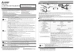
●
Installation
1)Open the moving core as shown Figure 1. Slowly lift the moving core locking claws on both sides of the moving core to open and removethem from the
stoppers. Before inserting the cable, check the symbols K and L to fit the current sensor in the correct direction. (The direction from the power supply side to the
load side is indicated with
→
.)(Figure 3)
2) After checking that the core parting faces are free from dirt, close the moving core. Push up the moving core until the stoppers are securely locked. (When the
moving core securing claws on both sides catch on the stoppers, you hear two clicks.)(Figure 2)
3) Pass the tying bands into the current sensor locking holes to secure the sensor with the cable.(Figure 3)
*
For the details, see the manual for combination measurement unit.
*
Applicable wire size in the table of specification is the normal sectional areas of 600V vinyl-coated cable.These values are the standard nominal sectional
areas.These electric wires may not pass through the sensor owing to the error of the outer diameters of vinyl insulators finished by manufacturers or
deformation (bending) of the wires.Check the wire on site.
●
Connection
・
For the details,
・
see the manual for the combination measurement unit.
3
Specification
Locking hole
(
3×2
)
Moving
core
Primary Cable
(Figure 1)
Moving core
parting face
Primary
Cable
(Figure 2)
Moving core
locking claw
Stopper
Moving core
locking claw
Direction
of current
(Figure 3)
*Buy the tying bands.
Direction
of current
Protective
cover
Tying bnd
K side set
LINE side
(LINE side)
(LOAD side)
<Usage as the CE marking conformity article>
・
As for the voltage to ground / line maximum voltage, 127V / 10%), the measurement category
Ⅲ
, pollution degree
Ⅱ
.
・
Install the current sensorto the secondaryof the circuit breaker.
・
Install the current sensor in the cabinet.
・
Use the PVC insulation electric wire.(less than heat-resistant temperature 70
°
C,the rating voltage 300V class.)
4
Service Network
Caution
Please refer to "catalog" or “user’s manual (Details)” for more detail.
HEAD OFFICE: TOKYO BUILDING, 2-7-3, MARUNOUCHI, CHIYODA-KU, TOKYO 100-8310, Japan
See the manual, please wire the polarity (Power supply side, Load side), 1 side (R phase), 2 side (S phase), 3 side (T phase) and the polarity (k, l) of the
secondary side of the CT to the k, l terminal of the measuring unit.
Model
EMU-CT50
EMU-CT100
EMU-CT250
Rated primary current
50A AC
~
100A AC
~
250A AC
~
Maximum voltage*
(voltage to ground
/
line voltage)
266V/460V AC
~
Frequency
45-65Hz
Ratio error
±1%
(
5%
~
100% of rating
,
RL
≦
10
Ω
)
Phase displacement
±0.9 c rad
(
5%
~
100% of rating
,
RL
≦
10
Ω
)
Measurement(installation)category
CAT
Ⅲ
Pollution degree
2
Applicable wire
size (reference)
IV wire
60mm
2
or less
150mm
2
or less
CV wire
38mm
2
or less
150mm
2
or less
Working temperature range
-5°C to +55°C (daily mean temperature: 35°C or less)
Working humidity range
5% to 95%RH (no condensation)
CE marking conformity standard
EN61010-2-32
CE marking conformity standard Maximum voltage
127V/220V +10
%
AC
~
CE marking conformity combination unit
UL
/
c-UL conformity combination unit
Unité à combinaison conformée au UL/c-UL standard
This sensor confirm UL/c-UL in a condition to make combination use with Mitsubishi MELSEC-Q
series programmable controllers Energy Measuring Unit (Models QE81WH,QE81WH4W,QE84WH
andQE83WH4W).
WhenEMU-CT50/100/250 is combined with EcoMonitorLight (Model:EMU4-BD1-MB, EMU4-HD1-MB),
EcoMonitorPlus(Model:EMU4-BM1-MB,EMU4-HM1-MB,EMU4-A2,EMU4-VA2),and Mitsubishi MELSEC
iQ-R series programmable controllers Energy Measuring Unit(Model RE81WH), it is necessary to confirm
compatibility with an end product.
CedétecteurestconforméauUL/c-UL standard sous condition d'être utilisé et combiné avec série MELSEC-Q
de Mitsubishi,appareil
de contrôle et programmable,Unité d'Energie Mesurage(Modèle QE81WH,
QE81WH4W,QE84WH etQE83WH4W).
Lorsque EMU-CT50/100/250 est combiné avec EcoMonitorLight (Modèle:EMU4-BD1-MB, EMU4-HD1-MB),
et EcoMonitorPlus(Modèle:EMU4-BM1-MB,EMU4-HM1-MB,EMU4-A2,EMU4-VA2),et MELSEC iQ-R de
Mitsubishi, appareil de contrôle et programmable, Unité d'EnergieMesurage (Modèle:RE81WH),
il est nécessaire de confirmer la compatibilité avec le produit final.
This sensor confirm CE marking standard in a condition to make combination use with Mitsubishi
MELSEC-Q series programmable controllers Energy Measuring Unit
(Models QE81WH, QE81WH4W, QE84WH, QE83WH4W), Mitsubishi MELSEC-iQ-R series
programmable controllers Energy Measuring Unit (Model RE81WH), EcoMonitorLight
(Model : EMU4-BD1-MB, EMU4-HD1-MB) and EcoMonitorPlus (Model : EMU4-BM1-MB, EMU4-HM1-MB,
EMU4-A2, EMU4-VA2)
* Please check the maximum voltage for the combination measurement unit.
Make sure to use the module by following cautions of this section.
<Precautions concerning installation and connection>
・
Any person who is involved in the installation and the wiring of this Programmable Controller should be fully competent to
do the work.
・
Use an electric wire of the size of penetrating this current sensor for a primary side cable, do not use a non-insulation electric
wire or a metalfor a primary cable.
・
When threading and wiring, take utmost care that cuttings and wire pieces do not enter the equipment.
・
Connect the wires carefully, checking the wiring diagram. Incorrect wiring can cause unit failures, fires, and electric shocks.
・
Perform wiring work with current off and do not perform live wire operations. Doing so can cause electric shocks, unit failures, and
fires.
・
After tightening, be sure to check that all screws have been tightened. Failure to tighten any screw can cause unit
malfunctions, fires, and electric shocks.
・
Use the M3.5 screws crimp type terminals (less than external form 7.2mm) appropriate for for which is suitable for electric
wire size (1.25mm
2
). The use of the infelicity causes malfunction of the machinery, trouble, a damage by a fire, the fire by outbreak of the
poor disconnection and contact.
・
UL
/
c-UL listed corresponds, use the wires according to the following conditions and UL-listed crimp type terminals.
Single wire
:
AWG24
~
AWG18
,
Stranded wire
:
AWG20
~
AWG18
・
75
℃
copper conductor only.
・
Confirm that a terminal is closed surely. The lack of clamping causes malfunction of the machinery, a fire, the electric shock.
・
Carry out the clamping of the crimp-type terminal lugs by prescribed torque (0.49 - 0.78N
・
m). The excessive clamping becomes
the ruination of a terminal and the screw.
・
Keep the second terminals 1cm or more away from the panel and the first conductor.
・
Read the manual of measuring units which is used with this current sensor , and is used well, and follow it.
・
Use this current sensor in cabinet certainly.
<To avoid getting shock>
・
As for the panel, it be assumed that it was given the following matters.
a)It is necessary to attach a key to the cabinet.
b)The structure that a power supply is intercepted automatically is necessary when opening a cabinet.
・
Degrees of protection(IP code)needs to higher than IP2X level.
<Precautions concerning usage>
・
Dust or rust on the split partcan degrade the performance of the current transformer . Wipe the dirt from the surface with soft dry cloth.
・
Usethe unit withinthe rated range stated here. Using the unit out ofthe rated range may cause not only malfunctions or unit failure,but
also fires orburnout.
・
The secondary side of the current sensorhas a built-in protective circuit against opening of the secondary terminal. No problem
occurs by
opening the terminal during wiring work. However, for safety,do not continuously apply current while the terminal is open.
Caution


