background image

SERVICE MANUAL

  CONTENTS

 1. SAFETY PRECAUTION ................................... 2
 2. SPECIFICATIONS ............................................ 8
  3. PART NAMES AND FUNCTIONS  .................. 9
 4. OUTLINES AND DIMENSIONS ..................... 10
 5. WIRING DIAGRAM .........................................11
 6. FIELD WIRING ............................................... 13
 7. WATER SYSTEM DIAGRAM ......................... 14
 8. CONTROLS ................................................... 17
 9. TROUBLESHOOTING ................................... 43
10. DISASSEMBLY PROCEDURE ...................... 78
11. SUPPLEMENTARY INFORMATION .............. 93
12. SERVICE AND MAINTENANCE ................... 94

R32

PARTS CATALOG (OCB722)
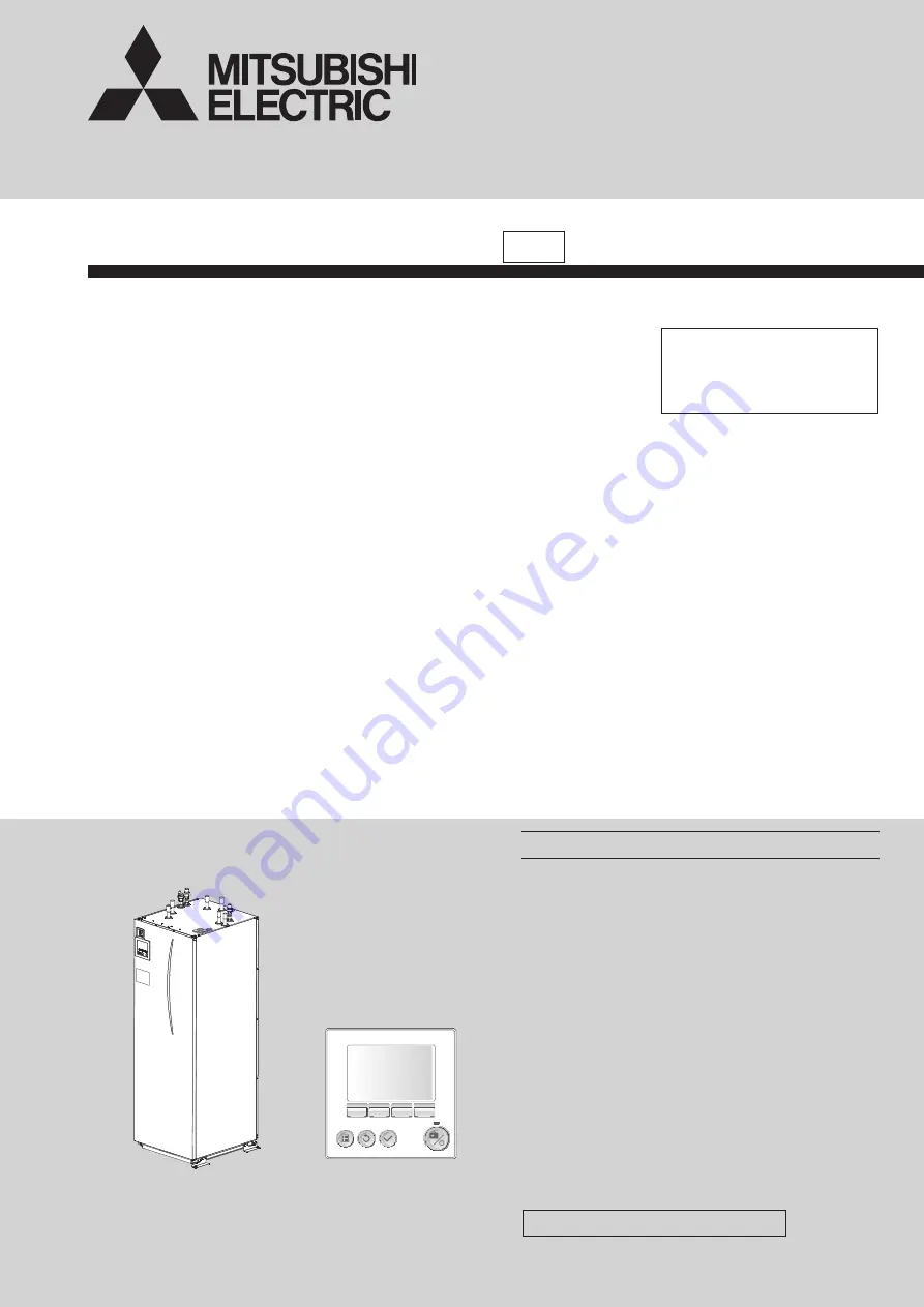
HEAT PUMP UNIT

HEAT PUMP UNIT

MAIN REMOTE 

CONTROLLER

December 2020

No. OCH722

REVISED EDITION-A

[Model Name]

EHGT17D-YM9ED

[Service Ref.]

EHGT17D-YM9ED.UK

Revision:

• DISASSEMBLY PROCEDURE 

has been modified in 

REVISED EDITION-A.

OCH722 is void.

Summary of Contents for EHGT17D-YM9ED

Page 1: ...14 8 CONTROLS 17 9 TROUBLESHOOTING 43 10 DISASSEMBLY PROCEDURE 78 11 SUPPLEMENTARY INFORMATION 93 12 SERVICE AND MAINTENANCE 94 R32 PARTS CATALOG OCB722 HEAT PUMP UNIT HEAT PUMP UNIT MAIN REMOTE CONTROLLER December 2020 No OCH722 REVISED EDITION A Model Name EHGT17D YM9ED Service Ref EHGT17D YM9ED UK Revision DISASSEMBLY PROCEDURE has been modified in REVISED EDITION A OCH722 is void ...

Page 2: ...r cold areas in the refrigerating cycle When the repair or the inspection of the circuit needs to be done without turning off the power exercise great caution not to touch the live parts Use a vacuum pump with a reverse flow check valve Vacuum pump oil may flow back into refrigerant cycle and that can cause deterioration of refrigerant oil etc Use the following tools specifically designed for use ...

Page 3: ...ure that there are no refriger ant leaks before performing the work If refrigerant leaks and accumulates it may ignite or poisonous gases may be released 11 Do not install the unit in places where refrigerant may build up or places with poor ventilation such as a semi base ment Refrigerant is heavier than air and inclined to fall away from the leak source 12 The appliance shall be stored in a room...

Page 4: ...nents are being changed they shall be fit for the purpose and to the correct specification At all times the manufacturer s maintenance and service guidelines shall be followed If in doubt consult the manufacturer s technical department for assistance The following checks shall be applied to installations using flammable refrigerants The charge size is in accordance with the room size within which ...

Page 5: ...e conventional procedures shall be used However for flammable refrigerants it is important that best practice is followed since flammability is a considera tion The following procedure shall be adhered to remove refrigerant purge the circuit with inert gas evacuate purge again with inert gas open the circuit by cutting or brazing The refrigerant charge shall be recovered into the correct recovery ...

Page 6: ...hat only appropriate refrig erant recovery cylinders are employed Ensure that the correct number of cylinders for holding the total system charge are available All cylinders to be used are designated for the recovered refrigerant and labelled for that refrigerant i e special cylinders for the recovery of refrigerant Cylinders shall be complete with pressure relief valve and associated shut off val...

Page 7: ...rant charge Tool exclusive for R32 Safety charger Prevent compressor malfunction when charging refrigerant by spraying liquid refrigerant Tool exclusive for R32 〇 Charge valve Prevent gas from blowing out when detaching charge hose Tool exclusive for R32 〇 Vacuum pump Vacuum drying and air purge Tools for other refrigerants can be used if equipped with adapter for reverse flow check Usable if equi...

Page 8: ...rculating Pump DC motor Connections Water 28 mm compression primary circuit 22 mm compression DHW circuit Brine 28 mm compression Guaranteed operating range Ambient 2 0 to 35 C 80 RH Brine inlet temperature 8 to 30 C Min Brine outlet temperature 12 C Operating range Heating Room temperature 10 to 30 C Flow temperature 20 to 60 C DHW 40 to 60 C Legionella prevention 60 to 70 C Flow rate range Prima...

Page 9: ...Optional parts 21 Level vessel Local supply 22 Pressure relief valve 10bar DHW Tank 23 Drain cock DHW tank 24 Pressure relief valve 3bar Local supply 25 Flow water temp thermistor THW1 26 Return water temp thermistor THW2 27 DHW tank water temp thermistor THW5A 28 DHW tank water temp thermistor THW5B 29 Refrigerant liquid temp thermistor TH2 30 Module 31 Drain pipe Local supply 32 Back flow preven...

Page 10: ...80 0 240 376 3 471 5 531 2 636 3 BORE HOLE RETURN CONNECTION 681 3 BORE HOLE FLOW CONNECTION 1738 8 UNIT HEIGHT FRONT MANOMETER MAIN CONTROLLER TERMINAL BLOCK FRONT PANEL LEFT SIDE HANDLE RIGHT SIDE HANDLE BACK HANDLE TOP F E A G C D B G1 2 4 1 Technical Drawings Letter Pipe description Connection size type A DHW outlet connection 22 mm Compression B Cold water inlet connection 22 mm Compression C...

Page 11: ...3 1 7 X6 X7 CNBHT BK CNBC GY CNBH WH N 3 L 1 4 2 BU RD 3 1 5 A1 4 2 6 A2 θ θ IHT IH B A BU RD 1 3 2 CNIH OG OG OG Immersion heater 1Ph1kW Option Power supply to Immersion heater N 230V 50Hz L3 5 L2 3 L1 1 4 2 WH RD 3 1 5 BK 6 4 2 6 WH RD BK A1 A2 3 1 5 WH RD BK ECB2 IHC ECB1 BHCP A1 4 2 6 A2 4 2 6 A2 3 1 5 A1 WH No 1 WH No 2 WH No 3 BU No 4 BU No 5 BU No 6 VT VT BHC2 BHC1 PK PK GY GY BH1 BH2 BHT B...

Page 12: ...al supply BHC2 BHCP IHT THW10 IHC TH1 TH2 THW1 THW2 THW5B THW6 THW7 THW9 IH THW5A BH1 BH2 BHC1 BHT BHF MP2 MP3 Symbol TB1 ECB1 ECB2 MP1 MP4 3WV 2WV2a 2WV2b MXV Name Terminal block Connector Item OFF Open ON Short IN1 TBI 1 7 8 Room thermostat 1 input 9 IN2 TBI 1 5 6 Flow switch 1 input IN3 TBI 1 3 4 Flow switch 2 input Zone1 IN4 TBI 1 1 2 Demand control input Normal Heat source OFF Boiler operatio...

Page 13: ...nductors of the supply 3 Use wires in conformity with design 60245 IEC 57 4 The values given in the table above are not always measured against the ground value Note 1 Wiring size must comply with the applicable local and national codes 2 Install an earth line longer than power cables 3 Please keep enough output capacity of power supply for each heater Insufficient power supply capacity might caus...

Page 14: ...Use only Mitsubishi Electric service parts as a direct replacement Refer to Table 3 1 for the part names Circuit diagram Figure 7 1 Outdoor Heat sink Cold water Local system 1 Water supply DHW Drain Indoor Bore hole Note To enable draining of the heat pump unit an isolating valve should be positioned on both the inlet and outlet pipework Be sure to install a strainer on the inlet pipework to the h...

Page 15: ...water temp thermistor THW7 5 Zone1 water circulation pump local supply 6 Motorized mixing valve local supply 7 Zone2 flow water temp thermistor THW8 8 Zone2 return water temp thermistor THW9 9 Zone2 water circulation pump local supply Optional part PAC TH011 E Optional part PAC TH011 E 10 Zone2 heat emitters e g underfloor heating local supply 11 Boiler flow water temp thermistor THWB1 12 Mixing t...

Page 16: ...the heater until the DHW tank is full of water Also do NOT energise any immersion heater if any sterilisation chemicals remain in the DHW tank as this will cause premature failure of the heater Initial flush procedure Energise system to heat up heat pump unit contents to a temperature of approx 30 40 C Flush drain the water contents to remove any residue impurities resulting from the installation ...

Page 17: ...isplayed the Electric heaters booster or immersion heater are in use 4 Target temperature Target flow temperature Target room temperature Compensation curve 5 OPTION Pressing the function button below this icon will display the option screen 6 Increase desired temperature 7 Decrease desired temperature 8 Z1 Z2 Pressing the function button below this icon switches between Zone1 and Zone2 Informatio...

Page 18: ...d 5 Press button E Power refer to page 41 to turn on the system Before turning on the system perform initial settings as instructed below Initial settings wizard DHW SETTINGS Operation mode 8 3 Initial settings wizard When the main remote controller is switched on for the first time the screen automatically goes to Language setting screen Date Time setting screen and Main set tings menu screen in ...

Page 19: ...get temperature space heating mode DHW mode any additional heat sources being used holiday mode and the date and time You should use the function buttons to access more information When this screen is displayed pressing F1 will display the current status and pressing F4 will take the user to the option menu screen Home screen Option screen Option screen This screen shows the main operating modes o...

Page 20: ...Non active Heating room temp Heating flow temp Heating compensation curve Compensation curve preview Compensation curve edit F1 F1 F3 F1 F2 F2 F2 F2 F4 F3 F3 F3 F4 F4 F3 F4 F2 F4 F3 F4 F2 F3 F4 DHW Date Time yyyy mm dd hh mm EN FR DE SV ES IT DA NL FI NO PT BG PL CZ RU TR SL OFF Room Tank Room Tank OFF ON hh mm hh mm AM AM hh mm C F Room RC zone select Sensor setting Zone1 Zone1 Zone2 Holiday mode...

Page 21: ...N5 FTC Main RC SD Yes No Select upload data Water pump input Electric energy meter Booster heater 1 capacity Pump 1 Booster heater 2 capacity Pump 2 Immersion heater Pump 3 Boiler Boiler Boiler efficiency Target temp Start Finish Temp increase step Temp decrease step Max temp Max temp period Increase interval Decrease interval Booster heater 2 capacity Booster heater 1 capacity Flow temp Increase ...

Page 22: ...lve can be manually overridden using manual operation mode When manual operation is selected a small timer icon appears in the screen The function selected will only remain in manual operation for a maximum of 2 hours This is to prevent accidental permanent override of the FTC Example Pressing F3 button will switch manual operation mode ON for the main 3 way valve When filling of the DHW tank is c...

Page 23: ... Minimum The minimum flow rate to be detected at Flow sensor Maximum The maximum flow rate to be detected at Flow sensor 1 Decreasing time before pump switched off may increase the duration of stand by in heating mode 2 Set the Running time according to the specifications of the actuator of each mixing valve It is recommended to set the interval to 2 minutes that is a default value With the interv...

Page 24: ...up a room Pump speed 1 From the Service menu highlight Pump speed 2 Press CONFIRM 3 The Pump speed screen is displayed 4 Use F2 and F3 buttons to set the pump speed of the water circulation pump between 1 and 5 Heat source setting The default heat source setting is heat pump and all electric heaters present in the system to be operational This is referred to as Standard operation on the menu Flow ...

Page 25: ...ation equals to the maximum temperature set in the Flow temp range menu Fast mode is not efficient and will increase running cost compared to normal mode Range of outdoor ambient temperature at which simultaneous operation starts is 30 to 10 C default 15 C System shall automatically return to routine operation This will happen when the outdoor ambient temperature rises above the selected temperatu...

Page 26: ...ied locally are connected as Pump2 3 change setting ac cording to specs of the pumps 1 Change setting to 1 kW when connecting optional immersion heater PAC IH01V2 E 2 displayed in the energy monitor setting mode means the factory fitted pump is connected as Pump 1 so that the input is automatically calculated When anti freeze solution propylene glycol is used for primary water circuit set the deli...

Page 27: ...cated on the water and refrigerant circuit Thermistor Description Thermistor Description TH1A Zone1 room temperature THW6 Zone1 flow water temperature TH1B Zone2 room temperature THW7 Zone1 return water temperature TH2 Refrigerant return temperature THW8 Zone2 flow water temperature THW1 Water flow temperature THW9 Zone2 return water temperature THW2 Water return temperature THW10 Mixing tank wate...

Page 28: ...Error history allows the service engineer to view previous error codes the unit address and the date on which they occurred Up to 16 error codes can be stored in the history the most recent Error event is displayed at the top of the list 1 From the service menu select Error history 2 Press CONFIRM Please see 9 4 Self diagnosis and action for error code diagnosis and actions To delete an Error hist...

Page 29: ... password If you forget the password you entered or have to service a unit somebody else installed you can reset the password to the factory default of 0000 1 From the main settings menu scroll down the functions until Service Menu is highlighted 2 Press CONFIRM 3 You will be prompted to enter a password 4 Hold down buttons F3 and F4 together for 3 seconds 5 You will be asked if you wish to contin...

Page 30: ...y 0 to 255 Hz 17 Compressor Target operating frequency 0 to 255 Hz 18 Brine pump output step 0 to 10 Step 19 Brine pump speed 0 to 9999 rpm 20 21 22 LEV A opening 0 to 500 Pulses 23 24 25 Primary current 0 to 50 A 26 DC bus voltage 180 to 370 V 27 C B Brine inlet temperature TH32 39 to 88 C 28 C B Brine outlet temperature TH34 39 to 88 C 29 30 31 32 33 34 35 36 37 38 39 40 41 42 43 44 45 46 47 48 ...

Page 31: ...ays if no history is present Code 105 Error history 3 third to last Displays error history is displays if no history is present Code 106 Abnormal thermistor display TH3 TH7 TH8 3 TH3 7 TH7 8 TH8 0 No thermistor error Sensor number 107 Operation mode at time of error Displayed in the same way as request code 0 108 Compressor Operating current at time of error 0 to 50 A 109 Compressor Accumulated op...

Page 32: ... to 88 C 514 FTC Zone2 return water temp THW9 39 to 88 C 515 FTC Boiler flow water temp THWB1 40 to 140 C 534 FTC DHW tank upper temp THW5A 39 to 88 C 535 FTC Mixing tank water temp THW10 40 to 140 C 540 Flow rate of the primary circuit 0 to 100 L min 550 FTC Error postponement history 1 latest Displays postponement code is displays if no postponement code is present 551 FTC Operation control at t...

Page 33: ...0 STOP FAN C COOL DRY H HEAT d DEFROST Relay output state Display Power currently Compressor Four way valve Solenoid valve supplied to compressor Outdoor unit Control state Request code 51 Data display State 0 0 0 0 Normal 0 0 0 1 Preparingforheatoperation 0 0 0 2 Defrost Compressor Frequency control state Request code 52 Data display 0 0 Frequency control state 2 Frequency control state 1 Frequen...

Page 34: ... ON ON ON ON ON ON ON ON ON ON ON ON ON Actuator output state 2 Display 52C SV2 SS 0 1 2 3 4 5 6 7 ON ON ON ON ON ON ON ON ON ON ON ON Error content U9 Request code 55 Data display Error content 1 Error content 2 0 0 Error content 1 Detected Display Overvoltage Undervoltage L1 phase Power synchronizing error error open error signal error 0 1 2 3 4 5 6 7 8 9 A b C d E F Error content 2 Detected Dis...

Page 35: ...ation 1 Display Defrost mode 0 Standard 1 For high humidity Setting information 2 Display Single Heat pump 3 phase cooling only 0 Single phase Heat pump 1 Cooling only 2 3 phase Heat pump 3 Cooling only Outdoor unit Capacity setting display Request code 70 Data display Capacity 10 50 9 35 11 60 14 71 20 100 25 125 28 140 40 200 50 250 ...

Page 36: ...0 1 0 1 1 1 0 0 00 3A 1 1 0 1 1 1 0 0 00 3B 0 0 1 1 1 1 0 0 00 3C 1 0 1 1 1 1 0 0 00 3D 0 1 1 1 1 1 0 0 00 3E 1 1 1 1 1 1 0 0 00 3F 0 OFF 1 ON SW1 SW2 SW3 SW4 SW5 Display 1 2 3 4 5 6 7 8 0 0 0 0 0 0 1 0 00 40 1 0 0 0 0 0 1 0 00 41 0 1 0 0 0 0 1 0 00 42 1 1 0 0 0 0 1 0 00 43 0 0 1 0 0 0 1 0 00 44 1 0 1 0 0 0 1 0 00 45 0 1 1 0 0 0 1 0 00 46 1 1 1 0 0 0 1 0 00 47 0 0 0 1 0 0 1 0 00 48 1 0 0 1 0 0 1 0...

Page 37: ...0 1 0 1 1 1 0 1 00 BA 1 1 0 1 1 1 0 1 00 BB 0 0 1 1 1 1 0 1 00 BC 1 0 1 1 1 1 0 1 00 BD 0 1 1 1 1 1 0 1 00 BE 1 1 1 1 1 1 0 1 00 BF 0 OFF 1 ON SW1 SW2 SW3 SW4 SW5 Display 1 2 3 4 5 6 7 8 0 0 0 0 0 0 1 1 00 C0 1 0 0 0 0 0 1 1 00 C1 0 1 0 0 0 0 1 1 00 C2 1 1 0 0 0 0 1 1 00 C3 0 0 1 0 0 0 1 1 00 C4 1 0 1 0 0 0 1 1 00 C5 0 1 1 0 0 0 1 1 00 C6 1 1 1 0 0 0 1 1 00 C7 0 0 0 1 0 0 1 1 00 C8 1 0 0 1 0 0 1 1...

Page 38: ... 1 0 0 xx 38 1 0 0 1 1 1 0 0 xx 39 0 1 0 1 1 1 0 0 xx 3A 1 1 0 1 1 1 0 0 xx 3B 0 0 1 1 1 1 0 0 xx 3C 1 0 1 1 1 1 0 0 xx 3D 0 1 1 1 1 1 0 0 xx 3E 1 1 1 1 1 1 0 0 xx 3F 0 OFF 1 ON OUT Display 1 2 3 4 5A 5B 6 7 0 0 0 0 0 0 1 0 xx 40 1 0 0 0 0 0 1 0 xx 41 0 1 0 0 0 0 1 0 xx 42 1 1 0 0 0 0 1 0 xx 43 0 0 1 0 0 0 1 0 xx 44 1 0 1 0 0 0 1 0 xx 45 0 1 1 0 0 0 1 0 xx 46 1 1 1 0 0 0 1 0 xx 47 0 0 0 1 0 0 1 0 ...

Page 39: ... 1 0 1 xx B8 1 0 0 1 1 1 0 1 xx B9 0 1 0 1 1 1 0 1 xx BA 1 1 0 1 1 1 0 1 xx BB 0 0 1 1 1 1 0 1 xx BC 1 0 1 1 1 1 0 1 xx BD 0 1 1 1 1 1 0 1 xx BE 1 1 1 1 1 1 0 1 xx BF 0 OFF 1 ON OUT Display 1 2 3 4 5A 5B 6 7 0 0 0 0 0 0 1 1 xx C0 1 0 0 0 0 0 1 1 xx C1 0 1 0 0 0 0 1 1 xx C2 1 1 0 0 0 0 1 1 xx C3 0 0 1 0 0 0 1 1 xx C4 1 0 1 0 0 0 1 1 xx C5 0 1 1 0 0 0 1 1 xx C6 1 1 1 0 0 0 1 1 xx C7 0 0 0 1 0 0 1 1 ...

Page 40: ...1 0 0 37 xx 0 0 0 1 1 1 0 0 38 xx 1 0 0 1 1 1 0 0 39 xx 0 1 0 1 1 1 0 0 3A xx 1 1 0 1 1 1 0 0 3B xx 0 0 1 1 1 1 0 0 3C xx 1 0 1 1 1 1 0 0 3D xx 0 1 1 1 1 1 0 0 3E xx 1 1 1 1 1 1 0 0 3F xx Displayed only when the request code is 553 0 OFF 1 ON OUT Display 8 9 10 11 12 13 14 15 0 0 0 0 0 0 1 0 40 xx 1 0 0 0 0 0 1 0 41 xx 0 1 0 0 0 0 1 0 42 xx 1 1 0 0 0 0 1 0 43 xx 0 0 1 0 0 0 1 0 44 xx 1 0 1 0 0 0 1...

Page 41: ...3D 0 1 1 1 1 1 0 0 00 3E 1 1 1 1 1 1 0 0 00 3F Input signal display Request code 176 554 Please refer to Table 1 on relevant wiring diagram whilst using the following 0 OFF open 1 ON short IN Display 1 2 3 4 5 6 7 8 0 0 0 0 0 0 1 0 00 40 1 0 0 0 0 0 1 0 00 41 0 1 0 0 0 0 1 0 00 42 1 1 0 0 0 0 1 0 00 43 0 0 1 0 0 0 1 0 00 44 1 0 1 0 0 0 1 0 00 45 0 1 1 0 0 0 1 0 00 46 1 1 1 0 0 0 1 0 00 47 0 0 0 1 ...

Page 42: ...deactivated Emergency operation In emergency operation an operation without connecting and main remote controller is possible When in Emergency operation the main control has NO control functions Space heating flow temp is restarted 40 C and DHW tank temp is restricted 50 C 1 Heater Heating for DHW and space heating is provided by the heater Activating emergency operation mode To activate emergenc...

Page 43: ...ior phenomena 3 If no obvious problem can be found continue to operate the unit NOTE Electrical components should only be replaced as a final option Please follow instructions in 9 4 Self diagnosis and action and 9 5 Troubleshooting by inferior phenomena fully before resorting to replacing parts 9 2 Test Run Before a test run After installation of pipework and electrical wiring recheck that there ...

Page 44: ... blockages Check the primary water circuit for leaks Check that the flow amount is within the recommended range 3 Valve operation fault 3 Check valves on primary water circuit are installed level 4 2 way valve local supply actuator fault 4 Electrically test to determine fault 5 3 way valve actuator fault 5 1 Electrically test to determine fault 2 Operate 3 way valve manually using the main remote ...

Page 45: ...Main remote controller or Room RC 1 8 is chosen for the Room Sensor setting in the Initial setting 4 Replace wireless remote controller or main remote controller 5 Incorrect setting of the DIP switch es 5 Check the DIP switch setting s L6 Circulation water freeze protection DHW Heating LP FS OS Error code displayed when THW1 detects a temp 1ºC for 10 consecutive seconds or THW2 detects a temp 3ºC ...

Page 46: ...fer to table in 9 6 Checking Com ponent Parts Function to determine if system pump meets requirements If more head required either add a pump of the same size or replace existing pump with capacity model See 10 DISASSEMBLY PROCEDURE for how to replace pump 2 Reduced flow in primary water circuit Due to 1 or more of the following Faulty pump insufficient air purge blocked strainer leak in water cir...

Page 47: ... connection of flow sensor Check flow sensor cable for damage or loose con nections LH Boiler circulation water freeze protection Flow rate of the heating circuit from the boil er may be reduced Check for water leakage strainer blockage water circulation pump function LJ DHW operation error type of external plate HEX 1 DHW tank water temp thermistor THW5A B has become detached from its holder 2 Fl...

Page 48: ...3 Electrical noise causes interference with FTC controller circuit board trans mission cable E1 E2 Main remote controller control board failure Error code E1 displayed if main remote control ler cannot access it is non volatile non power dependent memory Error code E2 is displayed when there is a fault with the main remote controller s internal clock 1 Fault with the main remote controller circuit...

Page 49: ...gged or broken pipe 1 Check piping and repair defect 2 Locked brine pump 2 to 5 3 Malfunction of brine pump Check heat pump unit and repair defect 4 Short cycle of refrigerant or brine circuit 5 Dirt of brine circuit heat exchanger 6 Decreased brine flow rate 6 Check the brine flow rate 7 Disconnection or contact failure of connector 63H on controller circuit board 7 to 9 Turn the power off and ch...

Page 50: ...ven though linear expansion valve has minimum open pulse after compressor starts operating for 10 minutes 1 Disconnection or loose connection of discharge temperature thermistor TH4 1 2 Check the installation conditions of discharge temperature thermistor TH4 2 Defective holder of discharge temperature thermis tor 3 Disconnection or loose connection of linear expansion valve s coil 3 Check the coi...

Page 51: ... of DC bus or com pressor is detected within 30 seconds after compressor starts operating 1 Decrease of power supply voltage 1 Check facility of power supply 2 Looseness disconnection or converse of com pressor wiring connection 2 Correct the wiring U V W phase to compressor 3 Defective compressor 3 Check compressor 4 Defective power board 4 Replace power circuit board UH 5300 Current sensor error...

Page 52: ...er circuit board unit is not supplied at the rated voltage 1 Check the voltage across the terminals L and N or L3 and N on the controller circuit board See 6 FIELD WIRING When the voltage is not 220 to 240 V AC check wiring of the unit and of the breaker When the voltage is at 220 to 240 V AC go to 2 below Check the N F board and TB1 cable 2 Faulty connector wiring 2 Check the cable between the te...

Page 53: ... thermal cut out has tripped and cannot be reset using the manual reset button 4 Check resistance across the thermal cut out if open then connection is bro ken and the booster heater will have to be replaced Contact your Mitsubishi Electric dealer 5 Immersion heater cut out has been triggered 5 Check immersion heater thermostat and press reset button located on immer sion heater boss if safe If th...

Page 54: ... 4 Check for correct setting of Running time 5 Motorized mixing valve failure 5 Inspect the mixing valve Refer to the manual included with each motorized mixing valve 15 After DHW operation room temperature rises slightly At the end of the DHW mode operation the 3 way valve diverts hot water away from the DHW circuit into space heating circuit This is done to prevent the unit components from overh...

Page 55: ... s and heat meter to FTC board Both should be locally supplied 1 Incorrect setting of the energy monitor 1 Check the setting by following the procedure below 1 Check if the DIP switch on FTC board is set as the table below Consumed electric energy SW3 4 Electric energy meter Local supply OFF Without ON With 2 In the case external electric energy meter and or heat meter is not used check if the set...

Page 56: ...ton lo cated on the top of the immersion boss See diagram on the left Flow sensor L Signal cable 3 3 Power cable BROWN PWM input signal Feedback signal Signal ref BLUE BROWN GREEN YELLOW BLUE BLACK M 1 N 0 80 70 60 50 40 30 20 10 0 5 10 15 20 25 30 Flow rate L min External static pressure kPa Speed 1 Speed 2 Speed 3 Speed 4 Speed 5 0 0 20 40 60 80 100 10 20 30 40 Lifting height kPa Flow rate L min...

Page 57: ... Normal Abnormal 1 2 2 3 1 3 105 8 11 8 5 Ω Open or Short 4 5 5 6 4 6 52 9 5 8 2 5 Ω Open or Short Earth leakage circuit breaker for heater If a short circuit occurs on the booster heater immersion heater or each power line a short circuit breaker will trip and power source will be blocked Eliminate the causes of short circuit and then turn on the breaker again Relay for heater R S T A1 A2 U V W W...

Page 58: ...nstall it Thermistors Thermistor TH3 Liquid Thermistor TH4 Discharge Thermistor TH7 Ambient Thermistor TH8 Heat sink Thermistor TH32 Brine inlet Thermistor TH33 Comp surface Thermistor TH34 Brine outlet Disconnect the connector then measure the resistance with a tester At ambient temperatures of 10 30 C Thermistor Normal Abnormal TH1 4 3 9 5 kΩ Open or short TH2 TH3 4 3 9 6 kΩ TH4 160 410 kΩ TH7 4...

Page 59: ...brine pump connector VDC 280 380 V DC TEST POINT 2 VCC between 5 and 4 of the brine pump connector VCC 15 V DC Replace the brine pump Replace the controller circuit board Replace the brine pump Replace controller board C B and brine pump MBP1 Replace controller circuit board Replace the brine pump Is the voltage normal Is the resistance abnormal Yes Yes No No Brine pump check CNF1 Is there contact...

Page 60: ... kΩ Thermistor R0 15kΩ 3 B constant 3480 1 Rt 15exp 3480 273 t 273 1 1 0 100 200 300 400 500 600 700 800 900 1000 30 20 10 0 10 20 30 40 50 60 70 80 Temperature C Resistance kΩ 0 C 162 8 kΩ 10 C 97 4 kΩ 20 C 60 3 kΩ 25 C 48 1 kΩ 30 C 38 6 kΩ 40 C 25 4 kΩ 50 C 17 1 kΩ 60 C 11 9 kΩ 70 C 8 4 kΩ 80 C 6 0 kΩ Thermistor R100 3 3kΩ 2 B constant 3970 1 Rt 3 3exp 3970 273 t 273 1 1 60 OCH722A 0 180 k 25 50...

Page 61: ...r when the valve is locked more sound can be heard No sound is heard when the pulse number moves from B to A in case coil is burnt out or motor is locked by open phase Sound can be detected by placing the ear against the screw driv er handle while putting the screw driver to the linear expansion valve LEV M 1 6 ø4 ø4 ø3 ø2 ø1 1 RD BU OG YE WH 2 3 4 5 Connector LEV A LEV B 12 VDC Outdoor controller...

Page 62: ...ess Be sure to attach the stopper to pipe B B A How to attach the coil Hold the lower part of the main body shown as A firmly so that the main body does not move and attach the coil by inserting it downward into the main body Then securely attach the coil stop per to pipe B At this time be careful that stress is not added to lead wire and main body is not wound by lead wire If the stop per is not ...

Page 63: ...BI 1 1 2 Demand control input IN3 TBI 1 3 4 Flow switch 2 input IN6 TBI 2 5 6 Room thermostat 2 input CNBC Signal output for booster heater 230 V AC OUT11 TBO 3 5 6 Signal output Error 230 V AC OUT5 TBO 2 1 3 Mixing valve Local supply 1 2 Close 230 V AC 2 3 Open 230 V AC CNP4 OUT14 Water circulation pump4 230 V AC OUT3 TBO 1 5 6 Water circulation pump3 Local supply 230 V AC OUT2 TBO 1 3 4 Water ci...

Page 64: ... V DC 1 3 Connect to the noise filter circuit board CNDC SW7 Function switch CN51 External signal output Compressor operat ing signal Abnormal signal LEV A Linear expansion valve SW8 Function switch CNM Connect to A control service tool CN2 Connect to the power cir cuit board CN2 1 5 Reception from power circuit board 2 5 Zero cross signal 0 5 V DC 3 4 Not used 6 5 15 V DC 7 5 15 V DC Controller c...

Page 65: ...ct to the controller circuit board CNAC CNDC Connect to the controller circuit board CNDC LO1 LO2 LO3 POWER SUPPLY LO1 LO2 LO2 LO3 LO3 LO1 AC400V OUTPUT Connect to the converter circuit board L1 IN ACL2 ACL3 CNCT Primary current Connect to the power circuit board CN5 CNL Connect to the ACL4 NO Connect to the converter circuit board N IN CNAC1 230VAC Connect to the controller circuit board CNAC ...

Page 66: ...rcuit board CNCT CN4 Connect to the con troller circuit board CN4 CN2 Connect to the controller circuit board CN2 1 5 Power circuit board Transmitting signal to the controller board 0 5V DC 2 5 Zero cross signal 0 5 V DC 3 4 Not used 6 5 15 V DC 7 5 15 V DC 5 1 2 6 7 CN7 Connect to the converter circuit board CN7 TB U TB V TB W Connect to the compressor MC Voltage among phases 10V 400V AC TB N Con...

Page 67: ...power circuit board CN7 CK OU Connect to the CK capacitor L1 IN N IN Connect to the noise filter circuit board LO1 NO L1 A1 Connect to the ACL1 L1 A2 L2 A2 L3 A2 Connect to the ACL1 ACL2 ACL3 L1 OU L2 OU L3 OU Connect to the power circuit board TB L1 L2 L3 ...

Page 68: ...4 OFF SW2 5 Automatic switch to backup heat source operation When compressor stops by error Inactive Active 1 OFF SW2 6 Mixing tank WITHOUT Mixing tank WITH Mixing tank OFF SW2 7 2 zone temperature control Inactive Active 2 OFF SW2 8 ON SW3 SW3 1 Room thermostat 2 input IN6 logic change Zone2 operation stop at thermostat short Zone2 operation stop at thermostat open OFF SW3 2 Flow switch 2 3 input...

Page 69: ...hen power supply ON OFF SW6 4 Model select Heat pump setting ON SW6 5 ON SW6 6 OFF SW6 7 ON SW6 8 OFF SW7 2 SW7 1 OFF SW7 2 OFF SW7 3 OFF SW7 4 OFF SW7 5 OFF SW7 6 Starting brine temp of borehole freeze prevention 2 C 0 C Always OFF SW8 SW8 1 Brine pump speed adjustment See Installation manual 4 4 Brine Pipe Works Always OFF SW8 2 OFF SW8 3 OFF SW9 SW9 1 Brine pump rotational speed adjustment See ...

Page 70: ...ly 2Check if noise entered into transmission wire of remote controller 3Re check error by turning off power and on again 1Check if FTC Controller circuit board connecting wire is connected correctly 2Check if noise entered into FTC Controller circuit board connecting wire or power supply 3Check if noise entered into FTC Controller circuit board controller board 4Re check error by turning off power...

Page 71: ...ing 2 Measure resistance values among terminals on compressor using a tester 3 Check leakage of refrigerant P48 Compressor overcurrent breaking UP P48 Abnormality of current sensor P B UH P48 Abnormality of power module U6 P47 5 blinking Open short of heat pump unit thermistors TH4 TH33 U3 1 Check if connectors TH3 TH32 TH34 TH4 TH33 and TH7 on controller circuit board and connector CN3 on power c...

Page 72: ...ps due to the work of protection devices Display Contents to be inspected When power is turned on F3 F5 F9 E8 E9 EA Eb EC EE E0 E7 63L connector red is open 63H connector yellow is open 2 connectors 63H 63L are open FTC Controller circuit board communication error Signal receiving error Controller circuit board FTC Controller circuit board communication error Transmitting error Controller circuit ...

Page 73: ... Example When 42500 times 425 100 times 0 5 s 0 5 s 2 s 0 to 9999 When it is 100 hours or more hundreds digit tens digit and ones digit are displayed by turns Example When 2450 hours 245 10 hours 0 5 s 0 5 s 2 s 1 ON 2 3 4 5 6 1 ON 2 3 4 5 6 Compressor operating current 0 to 50 0 to 50 Note Value after the decimal point will be truncated A Error postponement code history 1 of heat pump unit Postpo...

Page 74: ...ror history 0 and are displayed by turns 1 ON 2 3 4 5 6 Thermo ON time 0 to 999 Test run elapsed time 0 to 120 0 to 999 When it is 100 minutes or more the hundreds digit tens digit and ones digit are displayed by turns Example When 245 minutes 0 5 s 0 5 s 2 s 0 to 120 When it is 100 minutes or more the hundreds digit tens digit and ones digit are displayed by turns Example When 105 minutes 0 5 s 0...

Page 75: ...layed by turns 1 ON 2 3 4 5 6 Input current of heat pump unit 0 to 500 When it is 100 or more hundreds digit tens digit and ones digit are displayed by turns 0 1 A 1 ON 2 3 4 5 6 Secondary LEV opening pulse 0 to 500 Heating LEV A 0 to 500 When it is 100 pulse or more hundreds digit tens digit and ones digit are displayed by turns Pulse 1 ON 2 3 4 5 6 U9 error detail history latest Normal Overvolta...

Page 76: ...ens digit and ones digit are displayed by turns Example When 125 Hz 0 5 s 0 5 s 2 s Hz 1 ON 2 3 4 5 6 Fan step on error occurring 0 to 10 0 to 10 Step 1 ON 2 3 4 5 6 Return water temperature on error occurring 0 to 100 0 to 100 1 ON 2 3 4 5 6 Liquid pipe temperature TH2 on error occurring 39 to 88 39 to 88 When the temperature is 0 C or less and temperature are displayed by turns Example When 15 C...

Page 77: ... 00 is displayed 1 ON 2 3 4 5 6 Comp surface temperature TH33 52 to 221 52 to 221 When the temperature is 0 or less and tem perature are displayed by turns When the discharge thermistor detects 100 C or more hundreds digit tens digit and ones digit are displayed by turns Example When 105 0 5 s 0 5 s 2 s 1 ON 2 3 4 5 6 Controlling status of compressor operating frequency The following code will be ...

Page 78: ... wires as it may cause their breakage 11 Make sure the controller boards are fixed down to the support and free from looseness 12 Do not give any shock on the controller board 13 Any dust must not be attached on the controller board 14 Do not damage the mounted parts on the controller board 15 The wires must not move after being bundled with a cable strap 16 When bundling wires with a fastener be ...

Page 79: ...troller Photo 2 2 4 Separate the main remote controller from the main remote controller support Photos 2 1 and 2 3 3 How to remove the ATW controller board and the controller board 1 Remove the front panel Refer to Procedure 1 2 Disconnect the lead wires from the ATW controller board and the controller circuit board Photo 3 3 Remove the ATW controller board and the controller circuit board from th...

Page 80: ...oto 4 2 7 Remove the CONT base front from the control box 5 screws 4x10 Photo 4 3 8 Release the lead wires connected to the converter circuit board the noise filter circuit board and the power circuit board from the fasteners 9 Disconnect the lead wires from the converter circuit board the noise filter circuit board and the power circuit board Photo 4 4 10 Remove the converter circuit board and th...

Page 81: ...box Photo 4 2 8 Remove the screws fixing the control box and the side frame 6 screws 4x10 Photo 5 1 9 Disengage the tabs on the left then pull the control box and swing it to the right 10 Release the lead wires from the clamps on the back side of the control box Photo 5 2 11 Disengage the tabs on the right then remove the control box from the side frame Photo 5 1 Photo 5 1 Photo 5 2 6 How to remov...

Page 82: ... panel Refer to Procedure 1 2 Remove the frame Refer to Procedure 4 2 3 Remove the control box Refer to Procedure 5 4 Remove the P HEX Water Water Refer to Procedure 7 5 Remove the pipe tank EPHEX G3 4 nuts 3 4 gaskets Photo 8 1 6 Remove the ST band above the water pump sanitary circuit 2 screws 4x10 Photo 8 1 7 Remove the G1 nut and the 1 gasket on the water pump sanitary circuit Photo 8 1 8 Remo...

Page 83: ... using 2 spanners one to hold the G1 4 joint and the other to turn the manometer connection Figure 9 2 9 Remove the 2 screws to remove the manometer cover with the manometer from the side frame L by sliding it upward Figure 9 2 and 9 3 10 Remove the manometer from the manometer cover while pressing on the 2 claws Photo 9 1 When reinstalling the manometer assembly on the unit beware not to put stra...

Page 84: ...ening torque of the air vent automatic 3 5 1 N m Pressure relief valve 10 bar 1 Remove the field piping from the pressure relief valve 10 bar Figure 10 1 2 Remove the pressure relief valve 10 bar with the flare joint using 2 spanners one to hold the flare joint and the other to turn the flare nut Figure 10 5 3 Remove the pressure relief valve 10 bar using 2 spanners one to hold the flare joint and...

Page 85: ...ter heater Primary side pump power White 8 Brine pump White 10 Primary side pump control Flow sensor Pressure sensor 8 Release the lead wires from the clamp on the control box Photo 5 1 9 Release the lead wires from the P HEX Water Water Refer to Procedure 7 6 10 Release the lead wires from the clamp of the module box top Photo 11 3 11 Remove the 4 flexible pipes from the pipe of the unit assy 2 f...

Page 86: ...ve the TH32 lead wire Figure 13 2 If the pipe cover and the tape cannot be reused after removing TH32 obtain them locally 8 Release the lead wires from the clamps on the brine pump base Figure 13 2 9 Remove the brine pump assy and the pipe BPUMP BPHEX together the fastener and the O ring on the P HEX side 2 screws 4x10 10 Remove pipe BPUMP BPHEX from the brine pump The fastener and the O ring on t...

Page 87: ...nd lower G1 nuts and the 1 gaskets at 2 positions from the water pump assy Photo 14 4 Note Tightening torque of the G1 nuts 42 2 N m Tightening torque of the flow sensor 0 6 0 2 N m Photo 14 1 Photo 14 2 Photo 14 3 Photo 14 4 1 When replacing the pump only Remove the front panel Refer to Procedure 1 Remove the module box front then close the valves above and under the pump Remove the G1 nuts and t...

Page 88: ...he flexible pipe brine in Refer to Procedure 13 6 5 Remove the THW1 lead wire Photo 16 1 6 Release the lead wires from the clamp on B H stay Photo 16 1 7 Disconnect the relay connector of the booster heater 8 Remove the band C Photo 14 1 9 Remove the pipes pipe and the flexible pipe connected with an elbow from the booster heater the fastener and the O ring Photo 16 1 10 Remove the fastener and th...

Page 89: ...e booster heater Refer to Procedure 16 8 Recover refrigerant from the charge port Photo 17 1 9 Remove the band D fixing TH2 and TH33 lead wires Photo 17 2 and 17 3 10 Remove the rubber cushion and the band Photo 17 3 11 Remove the tape and the pipe cover from the LEV piping Photo 17 3 If the pipe cover and the tape cannot be reused obtain them locally 12 Detach the 2 brazing portions of the LEV fr...

Page 90: ...Disconnect the lead wire TH33 TH4 H P switch and the COMP wire in the terminal cover from the compressor Photo 18 2 11 Remove the INS SUC MUF from the compressor Photo 18 2 If the INS SUC MUF cannot be reused obtain it locally 12 Detach the brazing portions connecting the compressor and the discharge pipe and P HEX and the discharge pipe Photo 18 2 13 Remove the 4 bands and the 3 rubber cushions f...

Page 91: ...ositions on one side Photo 19 3 Photo 19 1 Photo 19 2 Photo 19 3 Photo 20 1 Photo 20 2 20 How to remove the compressor 1 Pull out the module unit assy Refer to Procedure 11 2 Remove the module box front Refer to Procedure 13 2 3 Remove the module box top module box side L module box side R and module box back Refer to Procedure 18 3 4 Remove the booster heater Refer to Procedure 16 5 Remove the CO...

Page 92: ...ARY SIDE PUMP THRU BACK OF PIPE FIX LEAD ASSY BOOSTER HEATER PRIMARY SIDE PUMP POWER LEAD ASSY BRINE PUMP LEAD ASSY PRIMARY SIDE PUMP CONTROL FLOW SENSOR PRESSURE SENSOR SANITARY SIDE PUMP LEAD WIRES AND CABLE ASSY 3 WAY VALVE WITH CLAMP Z Z FIX LEAD ASSY BRINE PUMP LEAD ASSY COMP AND LEAD ASSY REACTOR WITH CLAMPS 2 PLACES FIX LEAD ASSY BOOSTER HEATER PRIMARY SIDE PUMP POWER WITH CLAMPS 2 PLACES F...

Page 93: ... 10 3 Always use a new O ring or gasket Table 10 3 Size inch Recommended tightening torque Nm Gasket G1 4 8 1 G3 8 35 2 G3 4 42 2 G1 42 2 G1 3 4 10 1 Packing Strainer cover 40 2 O ring Flow sensor 0 6 0 2 Air vent Automatic 35 1 Flow switch Brine circuit 8 1 Attached packing Drain cock primary brine circuit 0 25 0 05 Air vent manual 0 25 0 05 Flare joint for water circuit parts 35 2 After the proc...

Page 94: ...er Hybrid 3 Standard Heat pump settings Heat pump flow rate range Minimum 0 to 100L min 5 L min Maximum 0 to 100L min 100 L min Quiet mode Day Mon to Sun Time 0 00 23 45 Quiet level Normal Level1 Level2 Normal Operation settings Heating operation 4 Flow temp range 6 Minimum temp 20 to 45 C 30 C Maximum temp 35 to 60 C 50 C Room temp control 9 Mode Normal Fast Normal Interval 10 to 60min 10min Heat...

Page 95: ...kW Analog output 0 to 30kW 0kW Delivered energy adjustment 50 to 50 0 Water pump input Pump 1 0 to 200W or factory fitted pump Pump 2 0 to 200W 0W Pump 3 0 to 200W 0W Pump 4 0 to 200W 72W Electric energy meter 0 1 1 10 100 1000 pulse kWh 1 pulse kWh Heat meter 0 1 1 10 100 1000 pulse kWh 1 pulse kWh External input settings Demand control IN4 Heat source OFF Boiler operation Boiler operation Outdoo...

Page 96: ...gainst factory recommendations 2 Check operation of motorized valves ensure they reseat correctly 3 Check battery power of wireless thermostat and replace if necessary Heat pump unit maintenance record sheet Model number Serial number Mechanical Frequency Notes 1 Inspect grill and air inlet for trapped debris damage 2 Check condensate drain provision 3 Check integrity of water pipework and insulat...

Page 97: ...97 OCH722A ...

Page 98: ... 3 MARUNOUCHI CHIYODA KU TOKYO 100 8310 JAPAN Copyright 2019 MITSUBISHI ELECTRIC CORPORATION Issued Dec 2020 No OCH722 REVISED EDITION A Published Oct 2019 No OCH722 Made in Japan Specifications are subject to change without notice ...

Reviews: