Mitsubishi Electric DX-KB5UE, Installation And Operation Manual
The Mitsubishi Electric DX-KB5UE is a cutting-edge product that offers exceptional performance and efficiency. With its comprehensive installation and operation manual, users can easily set up and operate the device. You can download the manual for free from manualshive.com to effortlessly maximize the potential of this remarkable Mitsubishi Electric product.
Share
Download


Reviews:
No comments
Related manuals for DX-KB5UE
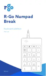
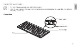
Numpad Break
Brand: R-Go Pages: 14
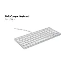
Compact
Brand: R-Go Pages: 11

2100
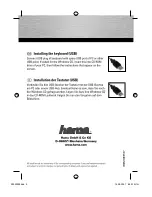
Brand: Hama Pages: 10
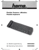
Nimble
Brand: Hama Pages: 10

98091
Brand: GE Pages: 9
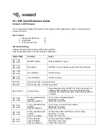
V3
Brand: WASD Pages: 4
Wireless Keyboard
Brand: Palm Pages: 20
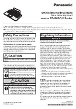
FZ-VKBQ11 Series
Brand: Panasonic Pages: 4
SXKC600 - ELECTRONIC KEYBOARD
Brand: Panasonic Pages: 48
VG-KBD2000
Brand: Samsung Pages: 10
EJ-BT230
Brand: Samsung Pages: 11
AK-120
Brand: Hama Pages: 2
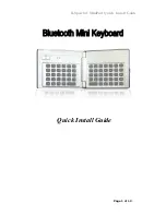
MiniPad
Brand: B-Speech Pages: 12
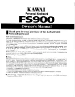
FS900
Brand: Kawai Pages: 48
H SERIES
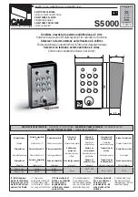
Brand: CAME Pages: 2

K5
Brand: Xtrfy Pages: 15
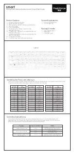
smart
Brand: Magicforce Pages: 2
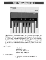
MP-1
Brand: Fatar Pages: 3


