Technical Training Manual
Including…
Down-to-1
High Speed Troubleshooting
ECHNICAL
RAINING
T
2011
2012
Copyright © 2011 Mitsubishi Electric Visual Solutions America, Inc.
All Rights Reserved
V45
Chassis
V46
Chassis
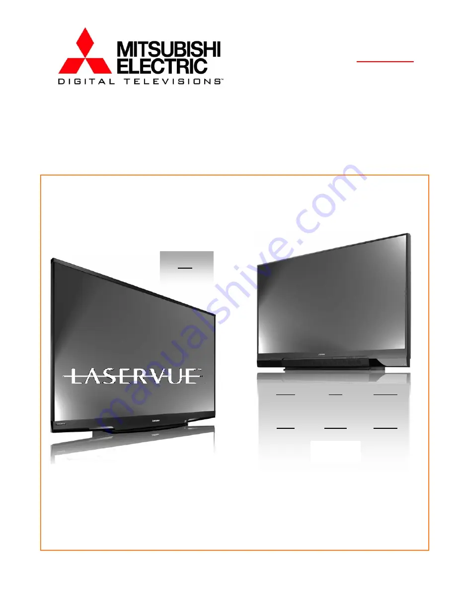
DLP
®
HOME CINEMA TV
V46
L75-A94
V45C V45 V45CA
WD-73C11 WD-73640 WD-73CA1
V45+ V45++ V45CB
WD-73740 WD-73840 WD-82CB1
WD-82740
WD-82840
WD-92840
Summary of Contents for DLP WD-82CB1
Page 2: ......
Page 4: ...4 ...
Page 9: ...9 Introduction ...
Page 69: ...DLP HOME CINEMA 69 CIRCUIT BLOCK DIAGRAMS ...
Page 70: ...DLP HOME CINEMA 70 CIRCUIT BLOCK DIAGRAMS ...
Page 71: ...DLP HOME CINEMA 71 ...
Page 72: ...DLP HOME CINEMA 72 ...
Page 73: ...DLP HOME CINEMA 73 ...
Page 74: ...DLP HOME CINEMA 74 ...
Page 75: ......