background image

Summary of Contents for CAHV-P500YB-HPB

Page 1: ......

Page 2: ...ire do not splash water on electric parts To reduce the risk of electric shock malfunctions smoke or fire do not operate the switches buttons or touch other electrical parts with wet hands To reduce the risk of electric shock and injury from the fan or other rotating parts stop the operation and turn off the main power before cleaning maintaining or inspecting the unit To reduce the risk of burns ...

Page 3: ...by the heat pump is not suitable for use as drinking water or for cooking It may cause health problems or degrade food In areas where temperature drops to freezing during the periods of non use blow the water out of the pipes or fill the pipes with anti freeze solution Not doing so may cause the water to freeze resulting in burst pipes and damage to the unit or the furnishings In areas where tempe...

Page 4: ... ceiling or floor All drainage work should be performed by the dealer or qualified personnel according to the instructions detailed in the Installation Manual Improper drainage work may cause rain water or drain water to enter the buildings and damage the furnishings Pipe installation To prevent explosion do not heat the unit with refrigerant gas in the refrigerant circuit Check for refrigerant le...

Page 5: ... the unit use appropriate tools to install inspect or repair the unit To reduce the risk or malfunction turn on the power at least 12 hours before starting operation and leave the power turned on throughout the operating season Recover all refrigerant from the unit It is punishable by law to release refrigerant into the atmosphere Do not unnecessarily change the switch settings or touch other part...

Page 6: ... the Unit 35 3 Unit Circuit Board 36 IV Remote Controller 1 Using the Remote Controller 43 2 Function Settings 48 V Electrical Wiring Diagram 1 Electrical Wiring Diagram 53 VI Refrigerant Circuit 1 Refrigerant Circuit Diagram 61 2 Principal Parts and Functions 62 VII Control 1 Functions and Factory Settings of the Dip switches 67 2 Operating characteristics and Control Capabilities 88 VIII Test Ru...

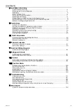
Page 7: ...CONTENTS HWE15070 GB ...

Page 8: ...ary Tools and Materials 4 3 Brazing 5 4 Air Tightness Test 6 5 Vacuum Drying Evacuation 7 6 Refrigerant Charging 8 7 Remedies to be taken in case of a Refrigerant Leak 8 8 Characteristics of the Conventional and the New Refrigerants 9 9 Notes on Refrigerating Machine Oil 10 ...

Page 9: ... 2 HWE15070 GB ...

Page 10: ...ing of this manual 4 Preparing necessary tools Prepare a set of tools to be used exclusively with each type of refrigerant Refer to Necessary Tools and Materials for information on the use of tools page 4 5 If there is a leak of gaseous refrigerant and the remaining refrigerant is exposed to an open flame a poisonous gas hydrofluoric acid may form Keep workplace well ventilated CAUTION Install new...

Page 11: ...n the high pressure side Charging Hose Evacuation and refrigerant charging Refrigerant Recovery Cylinder Refrigerant recovery Refrigerant Cylinder Refrigerant charging The refrigerant type is indicated The cylinder is Gray Charging Port on the Refrigerant Cylinder Refrigerant charging Tools Materials Use Notes Gas Leak Detector Gas leak detection The ones for use with HFC refrigerant may be used V...

Page 12: ...pper pipes or between a copper pipe and copper coupling If installed refrigerant pipes are not immediately connected to the equipment then braze and seal both ends 2 Reasons The new refrigerating machine oil is 10 times as hygroscopic as the conventional oil and is more likely to cause unit failure if water infiltrates into the system Flux generally contains chloride Residual flux in the refrigera...

Page 13: ... Refrigerant R407C must be charged in its liquid state vs gaseous state 2 Reasons Oxygen if used for an air tightness test poses a risk of explosion Only use nitrogen to check air tightness Refrigerant R407C must be charged in its liquid state If gaseous refrigerant in the cylinder is drawn out first the composition of the remaining refrigerant in the cylinder will change and become unsuitable for...

Page 14: ... more than 1Torr 130Pa 1hour after evacuation A rise by less than 1Torr 130Pa is acceptable If the vacuum is lost by more than 1Torr 130Pa conduct evacuation following the instructions in section 6 Special vacuum drying 5 Procedures for stopping vacuum pump To prevent the reverse flow of vacuum pump oil open the relief valve on the vacuum pump side or draw in air by loosening the charge hose and t...

Page 15: ...e use 7 Remedies to be taken in case of a Refrigerant Leak If the refrigerant leaks out all of the remaining refrigerant must be replaced with a new charge to maintain the proper composition of the refrigerant Repair the leak and then charge the system with the specified amount of refrigerant 5 5 kg Charge refrigerant in the liquid state Refer to IX 4 Refrigerant Leak page 146 Cylinder with a siph...

Page 16: ...ion wt 50 50 23 25 52 100 Type of Refrigerant Pseudo azeotropic Refrigerant Non azeotropic Refrigerant Single Refrigerant Chloride Not included Not included Included Safety Class A1 A1 A1 A1 A1 Molecular Weight 72 6 86 2 86 5 Boiling Point C F 51 4 60 5 43 6 46 4 40 8 41 4 Steam Pressure 25 C MPa 77 F psi gauge 1 557 226 0 9177 133 0 94 136 Saturated Steam Density 25 C kg m3 77 F psi 64 0 42 5 44 ...

Page 17: ...nants is defined as moisture air processing oil dust dirt wrong types of refrigerant and refrigerating machine oil Cause Symptoms Effects on the refrigerant cycle Water infiltration Frozen expansion valve and capillary tubes Clogged expansion valve and capillary tubes Poor cooling performance Compressor overheat Motor insulation failure Burnt motor Coppering of the orbiting scroll Lock Burn in on ...

Page 18: ...Configuration 13 2 Types and Maximum allowable Length of Cables 14 3 Main Power Supply Wiring and Switch Capacity 15 4 Sample Installation 17 5 Switch Types and the Factory Settings 18 6 Configuring the Settings 19 7 Water Pipe Installation 25 ...

Page 19: ... 12 HWE15070 GB ...

Page 20: ... or remote controller PAR W21MAA Field supplied dry contact switch relay or remote controller PAR W21MAA External temperature sensor Unit MAIN circuit PCB Unit SUB circuit PCB Each unit is operated individually by connecting a dry contact switch relay to each unit External temperature sensor Field supplied dry contact switch relay or remote controller PAR W21MAA MAIN unit SUB unit SUB unit s n uni...

Page 21: ...able for each refrigerant system Do not use a single multiple core cable to connect units that belong to different refrigerant systems The use of a multiple core cable may result in signal transmission errors and malfunc tions 2 Control wiring Different types of control wiring are used for different systems Types and maximum allowable length of cables Control lines are categorized into 2 types tra...

Page 22: ...eakage breaker for the inverter If no earth leakage breaker is installed there is a danger of electric shock Only use properly rated breakers and fuses Using a fuse or wire of the wrong capacity may cause malfunction or fire Note This device is intended for the connection to a power supply system with a maximum permissible system impedance shown in the above table at the interface point power serv...

Page 23: ...erminal Block Arrangement To remove the front panel of the control box unscrew the four screws and pull the panel forward and then down Important Power supply cables larger than 25 mm2 in diameter are not connectable to the power supply terminal block TB2 Use a pull box to connect them 2 Installing the conduit tube Punch out the knockout hole for wire routing at the bottom of the front panel with ...

Page 24: ...t is operated individually by connecting a dry contact switch relay to each unit External temperature sensor Field supplied dry contact switch relay or remote controller PAR W21MAA MAIN unit SUB unit SUB unit s n units Inter unit wiring M NET line Inter unit wiring M NET line Unit MAIN circuit PCB Unit SUB circuit PCB Unit MAIN circuit PCB Unit SUB circuit PCB Unit MAIN circuit PCB Unit SUB circui...

Page 25: ... to a certain position depends on the type of system configuration e g individual or multiple system REMOTE REMOTE Slide switch SWS2 Unused A A Push switch SWP1 Switches the display between the item code and the current value for a specific item Increases value Push switch SWP2 Switches the display between the item code and the current value for a specific item Decreases value Push switch SWP3 Adv...

Page 26: ... value is 60 0 To decrease this value to 58 0 for example press SWP2 Press SWP1 to increase the value To change the settings When the desired value is displayed 58 0 in the example at left press SWP3 Enter The displayed value will stop blinking and stay lit A lit LED indicates that the new setting has been saved Pressing SWP1 or SWP2 will change the blinking setting value but the change will not b...

Page 27: ... without remote 18 0 00 OFF time 3 schedule mode without remote 19 0 00 Current time 1 Set the current time TWL1 1057 40 Water temperature 1 for emergency signal 1 TAL1 1058 10 Outside temperature 1 for emergency signal 1 TWL2 1059 30 Water temperature 2 for emergency signal 2 TAL2 1060 15 Outside temperature 2 for emergency signal 2 Drain pan heater Defrost signal 1056 0 Selects between drain pan...

Page 28: ...lowing order 101 102 104 105 107 101 back to the beginning 3 Use SWP1 to increase the value and SWP2 to decrease the value 4 Press SWP3 to save the changed value Following the steps above set the value for the following items as necessary 101 Not used 102 Not used 104 Not used 105 Not used 107 Total number of units in the system Default 1 Leave it as it is A B Unit SUB circuit Unit MAIN circuit 10...

Page 29: ...iring M NET line The main unit is the unit to which an external water temperature sensor is connected Main unit Sub unit n th unit Unit MAIN circuit PCB Unit SUB circuit PCB Unit MAIN circuit PCB Unit SUB circuit PCB Sub unit Unit MAIN circuit PCB Unit SUB circuit PCB A B C Main unit SUB circuit Main unit MAIN circuit 10 s digit 0 1 s digit 1 0 10 s digit 5 1 s digit 1 0 Setting the switches on al...

Page 30: ... be set when multiple units are connected to a system 101 Not used 102 Not used 104 Not used 105 Not used 107 Total number of the main and sub units in the system EEEE 9999 Main unit MAIN circuit Main unit SUB circuit Sub unit MAIN and SUB circuits 10 s digit 0 1 s digit 1 0 10 s digit 5 1 s digit 1 0 Switch Settings dependon the unit A B 10 s digit 0 1 s digit 1 0 4 Perform an initial setup on th...

Page 31: ...ar Then five seconds later FFFF will appear 3 Press and hold the push switch SWP3 again for one second or longer While the system is starting up 9999 will appear on LED1 When start up is complete a control property 0012 will appear Then five seconds later FFFF will appear 4 Set the rotary switch SWU3 back to 0 6 Resetting the system MAIN and SUB circuits Take the following steps to reset the syste...

Page 32: ...ssure loss and supply sufficient water to the unit Install air venting valves to the places where air can accumulate Automatic air vent valves such as are effective Install an expansion tank to accommodate expanded water and to supply water Use pipes that allow for easy air purging and provide adequate insulation Install drain valves so that water can be drained for servicing Install a strainer ne...

Page 33: ... the water quality and check for possible corrosion Corrosion can occur in water systems in which there has been no signs of corrosion If the water quality level has dropped adjust the water quality before replacing the unit Items Lower mid range temperature water system Water Temp 60ºC Higher mid range temperature water system Water Temp 60ºC Tendency Recirculating water Make up water Recirculati...

Page 34: ...terial between pipes that are made of different materials to keep them out of direct contact with each other 7 In the case that the unit is installed in higher than storage tank Note the following Air pockets inside of heat exchanger will cause to corrode or scale up Refer to the lower diagram 1 Provide air vent valve at the unit outlet to let the air certainly go through 2 Keep the height differe...

Page 35: ...e installation angle insulation thickness and maintenance space The dimensions given below indicate the amount of space necessary when screwing in a Y shaped strainer 2 Installing a flow switch Install a flow switch that meets the following specifications on the water pipe Connect the flow switch to the flow switch contact on the unit Minimum flow rate 7 5 m h 125 L min Unit usage range water flow...

Page 36: ...erate properly during the defrost cycle The table below shows the minimum al lowable amount of water in the water circuit If the piping length is too short to secure this amount install a cushion tank to ensure that the circuit has enough water in it 2 Calculating the amount of water in the circuit The amount of water in the circuit can be obtained using the following formula Amount of water in th...

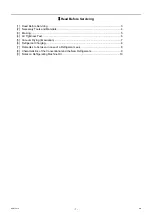
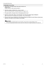
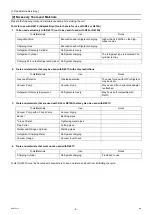
Page 37: ... 30 II Restrictions GB HWE15070 ...

Page 38: ... 31 HWE15070 GB III Unit Components 1 Unit Components and Refrigerant Circuit 33 2 Control Box of the Unit 35 3 Unit Circuit Board 36 ...

Page 39: ... 32 HWE15070 GB ...

Page 40: ...anel assy F Panel 1 Panel assy FBL Cover piping Panel M Panel B Frame assy B Fin guard B Pillar B Guard fixed plate Guard fixed plate Pillar B R Pillar B L Panel assy FB Panel assy FU Pillar F L Pillar LF Panel TOP Pillar RF Pillar F R Fan guard Fin guard LR Frame assy MB Frame assy MU Pillar RF Frame F Frame FB Attachment leg Base fan Upset screw Box nut Fan Motor H screw WFT screw ...

Page 41: ...ainer UL Thermistor Check valve Pressure sensor LP Four way valve Pressure switch Four way valve Solenoid coil Strainer UL Solenoid coil Strainer UL Thermistor Strainer Strainer Check valve Thermistor Thermistor Linear expansion valve Linear expansion valve Thermistor TH1 TH9 TH11 TH13 TH16 TH12 TH16 TH12 TH8 TH5 TH4 Solenoid valve Solenoid coil Solenoid valve Solenoid coil Expansion valve Solenoi...

Page 42: ...n terminals have a locking function Make sure the cable heads are securely locked in place Press the tab on the ter minals to remove them Control board DC reactor DCL Electromagnetic relay 72C Noise filter Note 1 INV board Fan board Capacitor Rush current protection resister Terminal block for power supply L1 L2 L3 N TB2 Terminal block TB1 Control terminal block1 Control terminal block2 Control bo...

Page 43: ...al display Dip switch SW1 3 Push switch SWP1 3 LED3 Energization status Dip switch SW421 External signal input contact input F01 Fuse 250V 3 15A LED2 Lit during normal CPU operation CNIT Output 12VDC GND Output 5VDC RX Power supply detection input TX Power supply ON OFF signal output CNS2 Transmission line input output for centralized control system CN102 outdoor transmission line input output 30V...

Page 44: ...lized control system CNIT 12VDC input GND 5VDC input Power supply detection output Power supply ON OFF signal input LED1 Power supply for indoor transmission line TP1 2 Check pins for outdoor transmission line TB7 Terminal block for transmission line for centralized control TB3 outdoor transmission block Ground terminal for transmission line Grounding Grounding CN04 Bus voltage input P N Grounding...

Page 45: ...terminal P Note Bus voltage check terminal N Note 1 SC P2 Bus voltage Input P SC P1 Rectifier diode output P LED1 Lit Inverter in normal operation Blink Inverter error CN6 Open No load operation setting Short circuited Normal setting CN5V GND 5VDC output RSH1 Overcurrent detection resistor CN4 GND Fan Board Serial communication signal output CN2 Serial communication signal output GND 17VDC input S...

Page 46: ...CN4 GND Serial communication signal output CN5 GND Control board Serial communication signal output CN21 Serial communication signal output GND INV board Input 17VDC CN22 GND INV board Input 5VDC Serial communication signal input GND INV board Output 17VDC LED1 Inverter in normal operation LED2 Inverter error DIP IPM Rear R630 R631 Overcurrent detection resistor ...

Page 47: ... CN5 Output Rectified L2 N current P N TB21 Input output L1 TB22 Input output L2 TB23 Input output L3 TB24 Input N CN1B Input L3 L2 CN1A Input N L1 Grounding F1 F2 F3 F4 Fuse 250VAC 6 3A CN3 Output L1 N Grounding CN2 Surge absorber circuit Surge absorber circuit Short circuit Short circuit ...

Page 48: ... 41 HWE15070 GB IV Remote Controller 1 Using the Remote Controller 43 2 Function Settings 48 ...

Page 49: ... 42 HWE15070 GB ...

Page 50: ...rned off To select the Mode 1 With the power turned on press the Mode BACK button until the desired mode appears Each press changes the operation mode in the following sequence see notes 1 and 2 below Heating Heating ECO Hot water Anti freeze Cooling Back to Heating The currently selected mode will appear in the area labeled 1 The available modes vary depending on the model 2 Refer to 4 2 2 page 4...

Page 51: ... 2 Press the TIMER ON OFF SET DAY button to set the day labeled in the figure Each press advances the day 3 Press the Set Time button as necessary to set the time When the button is held down the time at will increment first in one minute intervals then in ten minute intervals and then in one hour intervals 4 After making the appropriate settings in Steps 2 and 3 press the CIR WATER button to save...

Page 52: ...cedure and return to the Normal Operation screen 12 To activate the timer press the TIMER ON OFF button so that the Timer Off icon disappears If no timer settings have been made the Timer Off icon will flash on the screen How to View the Weekly Timer Settings 1 Make sure that WEEKLY is displayed 2 Press the TIMER MENU button so that Monitor appears on the screen 3 Press the TIMER ON OFF SET DAY bu...

Page 53: ...Viewing the Current Simple Timer Settings 1 Make sure that SIMPLE is displayed 2 Press the TIMER MENU button so that Monitor appears on the screen If the ON or OFF simple timer is running the current timer value will appear in the area labeled If ON and OFF values have both been set the two values will appear alternately 3 Press the Mode BACK button to close the monitor display and return to the N...

Page 54: ... pressed 5 Press the Mode BACK button to complete the setting procedure and return to the Normal Operation screen 6 If the unit is already running the timer will start counting down immediately Make sure that the remaining time is displayed on the screen and that it is correct Checking the Current Auto Off Timer Setting 1 Make sure that AUTO OFF is displayed 2 Press and hold the TIMER MENU button ...

Page 55: ... temperature unit C or F 2 Water temperature display setting WATER TEMP DISP SELECT Use to show or hide the water temperature PAR W21MAA ON OFF TEMP MENU BACK DAY CHECK TEST MONITOR SET CLOCK CLEAR ON OFF INITIAL SETTING CIR WATER Normal Operation screen Screen that appears when the unit is not running Press and hold the and buttons for two seconds No settings can be changed during a test run and ...

Page 56: ... ON OFF button to toggle through the following options Setting the contact number To set the contact number follow the following procedures Press the TEMP or button to move the cursor to the right left Press the CLOCK or button to set the contact number 5 Temp offset setting Press the ON OFF button to toggle between the following options 4 4 Display options 1 Temperature unit C F setting Press the...

Page 57: ... IV Remote Controller 50 HWE15070 GB ...

Page 58: ... 51 HWE15070 GB V Electrical Wiring Diagram 1 Electrical Wiring Diagram 53 ...

Page 59: ... 52 HWE15070 GB ...

Page 60: ...red white white D1 R04 R32 R06 CN2 C31 CN18V blue U Z4 C17 CN4 red TB21 CN1B L1 CN1A red Noise Filter TB22 CN3 green TB24 Fan motor Heat exchanger Water side Heat exchanger N C33 TB23 IPM FAN Board F05 AC DC400V 10A T 2 M 3 MS 3 black U red Diode Bridge 2 72C 1 black SC P2 C7 C8 CT12 L2 R5 U LED1 Normal operation red C35 DCL SC L2 SC P1 SC U CN1 black black C37 CN5V yellow C1 C9 C10 CN6 4 C100 LED...

Page 61: ...402 green CNS2 yellow CN102 CN102 CNIT red B S TP2 A A M1 B M2 TB3 TP1 Transmission power board CN04 red Transmission power circuit TB7 LED1 Power feeding X01 X02 CN502 CN501 CH SV1 21S4 M CNLVC blue M CNLVA To MAIN BOX MA 2 MB To MAIN BOX TB2 CNS2 yellow CNIT red TB4 CN52C red C5 Z5 C3 C2 F02 R01 R02 F01 R03 Z1 Z2 R34 C30 C32 C34 C36 black F03 F04 AC250V 6 3A T black white L F01 F02 F03 AC250V 6 ...

Page 62: ... 8 High pressure switch Solenoid valve Injection circuit 4 way valve Low pressure sensor Crankcase heater for heating the compressor Thermistor Compressor motor MS M TH1 4 TH14 16 TH9 11 63LS CH LEV2 21S4 SV1 Ac current sensor Capacitor Electrolysis F06 F05 F04 F03 F02 F01 CT3 CT22 CT12 MAIN BOX SUB BOX Field supplied MAIN BOX and SUB BOX Symbol explanation explanation Symbol Function setting conn...

Page 63: ...ATER TEMP SETTING CAPACITY CONTROL Water temperature or capacity control can be set by using the external analog input to the CN421 on the MAIN circuit board One analog input type can be selected from the following types 4 20 mA 1 5 V 0 10 V or 2 10 V Selection between drain pan output and defrost output can be made using the item code 1051 Note Use a 4 20 mA signal output device with insulation C...

Page 64: ...UNIT OPERATION RUN STOP External Water Temperature Sensor optional TH15 External Water Temperature Sensor optional TH14 M NET REMOTE CONTROLLER PUMP INTERLOCK Normal Error FAN MODE FORCED NORMAL 230 V VOLTAGE PUMP OPERATION COMMAND OPERATION INDICATOR ERROR INDICATOR ...

Page 65: ... 58 V Electrical Wiring Diagram GB HWE15070 ...

Page 66: ... 59 HWE15070 GB VI Refrigerant Circuit 1 Refrigerant Circuit Diagram 61 2 Principal Parts and Functions 62 ...

Page 67: ... 60 HWE15070 GB ...

Page 68: ...cuits like the one in the diagram below 63HS 63LS 21S4 63H1 Check joint high pressure Check joint low pressure Solenoid valve Injection circuit Solenoid valve Hot gas circuit 4 way valve High pressure switch Water side heat exchanger Water inlet Water outlet Air side heat exchanger Subcool heat exchanger Refrigerant flow direction during heating Refrigerant flow direction during defrost Table of s...

Page 69: ...es high pressure protection 3 85MPa OFF setting Thermi stor TH4 Discharge 1 Detects discharge air temperature 2 Provides high pressure protection Degrees Celsius Resistance check 0 C 32 F 698kohm 10 C 50 F 413kohm 20 C 68 F 250kohm 30 C 86 F 160kohm 40 C 104 F 104kohm 50 C 122 F 70kohm 60 C 140 F 48kohm 70 C 158 F 34kohm 80 C 176 F 24kohm 90 C 194 F 17 5kohm 100 C 212 F 13 0kohm 110 C 230 F 9 8koh...

Page 70: ...ord heater ohm 45W Resistance check 4 way valve 21S4 Changeover between heating and defrost AC220 240V Dead defrost cycle Live heating cycle Continuity check with a tester Fan motor FAN motor Regulates the heat exchanger capacity by adjusting the oper ating frequency and operating the propeller fan based on the operating pressure AC342V 50 5Hz 920W Linear expan sion valve LEV2 INJ control Adjusts ...

Page 71: ... VI Refrigerant Circuit 64 HWE15070 GB ...

Page 72: ... 65 HWE15070 GB VII Control 1 Functions and Factory Settings of the Dip switches 67 2 Operating characteristics and Control Capabilities 88 ...

Page 73: ... 66 HWE15070 GB ...

Page 74: ...ion Selects either the external water temperature sensor or the built in sensor to be used to control water temperature OFF Built in sensor on the unit External water temperature sensor At a reset 9 Individual Multiple system Selects between individual and Multiple system OFF Individual system Multiple system At a reset 10 Display mode switch 7 This switch is used in combination with dip switches ...

Page 75: ...put signal of the MAIN circuit REMOTE Unit Operation SWS1 Setting Main unit MAIN circuit Sub unit MAIN circuit Main unit MAIN circuit Main unit SUB circuit Sub unit MAIN circuit Sub unit SUB circuit LOCAL LOCAL Follows the input signal of the MAIN circuit on the Main unit Follows the input signal of the MAIN circuit on the Main unit Follows the input signal of the MAIN circuit on the Sub unit Foll...

Page 76: ... Manual setting Schedule setting SW2 7 ON Ineffective Ineffective Ineffective Ineffective Ineffective Temperature setting for the analog signal input TH14 SW2 7 OFF When schedule has been set Ineffective Ineffective Ineffective Ineffective Selectable from temperature settings A through C Selectable from TH14 or TH15 When no schedule has been set ON Heating Eco ON Hot water Ineffective Ineffective ...

Page 77: ... VII Control 70 HWE15070 GB Water temperature setting Different water temperature settings can be set for different modes Use item codes 11 13 22 23 24 25 26 or 27 to set the water temperatures ...

Page 78: ...late to water temperature setting Press the push switch SWP3 to select an item code Press the push switches SWP1 and SWP2 to change the value of the selected item The value will keep blinking while it is being changed Settings can be changed from the optional remote controller regardless of the ON OFF status of the operation switch 0 Outdoor temperature sensor TH9 1 IT terminal SW2 SW3 10 5 6 7 8 ...

Page 79: ...ng C3 Heating ECO Outside temp setting C2 Heating ECO Outside temp setting C4 Outside temp Water temp setting Heating ECO Water temp setting C1 Heating ECO Water temp setting C3 Outside temp When the values for C2 and C4 are set to the same value Water temp Water temp setting C1 Water temp setting C3 Outsidetemp setting C2 Outside temp setting C4 Outside temp Always use a value for setting C6 that...

Page 80: ...he display will stop blinking and stay lit The display will then return to the item code display mode If SWP3 is not pressed within one minute the change will not be saved and the display will return to the item code display mode SW2 SW3 10 5 6 7 8 9 10 OFF OFF OFF OFF OFF ON OFF Settings table Settable item Item code Initial value Unit Limits and increments Increments Lower limit Upper limit 9 5 ...

Page 81: ...peration periods 2 and 3 overlap Refer to the section on how to select the preset water temperatures on the next page Operation Period 1 Operation Period 2 Operation Period 3 Target water temp Operation command signal Operation Period 1 Operation Period 2 Operation Period 3 Set temp Operation command signal Operation Period 1 Operation Period 2 Operation Period 3 Set temp Operation command signal ...

Page 82: ...ue Step 4 Press the push switch SWP3 to save the change Press SWP3 once within one minute of changing the setting with SWP1 or SWP2 to save the setting Once the new setting is saved the display will stop blinking and stay lit The display will then return to the item code display mode If SWP3 is not pressed within one minute the change will not be saved and the display will return to the item code ...

Page 83: ...ode 1220 Operation time setting 3 Item code 1217 Preset temp 3 Item codes 22 27 Heating ECO Example 1 Example 2 Example 3 1 2 Start time 1 End time 1 Operation 1 Preset temperature is selectable from A B or C Heating Heating Hot Water 3 4 Start time 2 End time 2 Operation 2 Preset temperature is selectable from A B or C Hot Water Hot Water Heating ECO 5 6 Start time 3 End time 3 Operation 2 Preset...

Page 84: ...ep 2 Select the desired item with the push switch SWP3 Press the push switch SWP3 to select item code 2 Press the push switches SWP1 or SWP2 to change the value of the selected item The value will keep blinking while it is being changed Step 3 Press the push switches SWP1 or SWP2 to increase or decrease the value Step 4 Press the push switch SWP3 to save the change Press SWP3 once within one minut...

Page 85: ...tep 3 Press the push switches SWP1 or SWP2 to increase or decrease the value Step 4 Press the push switch SWP3 to save the change Press SWP3 once within one minute of changing the setting with SWP1 or SWP2 to save the setting Once the new setting is saved the display will stop blinking and stay lit The display will then return to the item code display mode If SWP3 is not pressed within one minute ...

Page 86: ...e operation signal is off A will be displayed while the compressor is in operation S will be displayed while the compressor is stopped S will be displayed while the fan is forced to operate will be displayed when this function is disabled d will be displayed when the peak demand control function is enabled will be displayed when this function is disabled Displays the operation mode H will be displ...

Page 87: ...s will blink Press SWP3 once within one minute of changing the settings to save the change When the new setting is saved the display will stop blinking and stay lit The display will then return to the item code display mode If SWP3 is not pressed within one minute the change will not be saved and the display will return to the item code display mode Step 1 Set dip switches SW2 SW3 SW421 1 and SW42...

Page 88: ...ut signal type is set to 2 1 5 V External analog input signal of 1 5 V Preset temp A Item code 11 External analog input signal of 4 5 V Preset temp B Item code 13 External analog input signal of between 1 5 and 4 5 V the preset temperature will be linearly interpolated 3 W S 2 W S 10 5 6 7 8 9 10 Switch settings OFF OFF OFF OFF OFF ON OFF Items that can be set Item code Initial value Unit Setting ...

Page 89: ...signal type is set to 1 0 10 V External analog input signal of 1 0 V 0 External analog input signal of 9 1 V 100 External analog input signal of between 1 0 and 9 1 V the percent will be linearly interpolated Preset temp B Preset temp A 2 9 V Input voltage 9 1 V Preset temperature B A Input voltage 2 9 V 6 2 V A Change of 59 mV or less is not recognized 3 W S 2 W S 10 5 6 7 8 9 10 Switch settings ...

Page 90: ...xternal analog input signal of 9 1 V 100 External analog input signal of between 2 9 and 9 1 V the percent will be linearly interpolated 100 0 1 5 V Input voltage 4 5 V Load ratio Preset temperature 100 Input voltage 1 5 3 0 V Change of 29 mV or less is not recognized 100 0 2 9 V Input voltage 9 1 V Load ratio Preset temperature 100 Input voltage 2 9 V 6 2 V Change of 59 mV or less is not recogniz...

Page 91: ...Water temperature control option is set to OFF the water temperature drops below TWL1 and the outside temperature drops below TAL1 2 Water temperature control option is set to ON the external water temperature sensor reading drops below TWL1 and the outside temperature drops below TAL1 External water temperature sensor readings TH14 and TH15 drop below TWL1 and the reading of the outside temperatu...

Page 92: ...rn to the item code display mode If SWP3 is not pressed within one minute the change will not be saved and the display will return to the item code display mode Step 2 Set dip switches SW2 and SW3 3 W S 2 W S 10 5 6 7 8 9 10 Switch settings OFF OFF OFF OFF OFF ON OFF Step 3 Select the item to be set with push switch SWP3 Step 4 Change the values with push switches SWP1 or SWP2 Items that can be se...

Page 93: ...Water temperature control option is set to OFF the water temperature drops below TWL2 and the outside temperature drops below TAL2 2 Water temperature control option is set to ON the external water temperature sensor reading drops below TWL2 and the outside temperature drops below TAL2 External water temperature sensor readings TH14 and TH15 drop below TWL2 and the reading of the outside temperatu...

Page 94: ...rn to the item code display mode If SWP3 is not pressed within one minute the change will not be saved and the display will return to the item code display mode Step 2 Set dip switches SW2 and SW3 3 W S 2 W S 10 5 6 7 8 9 10 Switch settings OFF OFF OFF OFF OFF ON OFF Step 3 Select the item to be set with push switch SWP3 Step 4 Change the values with push switches SWP1 or SWP2 Items that can be se...

Page 95: ... gas temperature of 120ºC or above has been detected for 30 seconds while the com pressor is in operation Preliminary abnormal stop If this happens three times the unit will make an abnormal stop If a discharge gas temperature of 125ºC or above was detected the unit will make an abnormal stop Air side HEX inlet temp vacuum protec tion TH4 TH8 Air side HEX inlet temp OFF ºC A heat side heat exchang...

Page 96: ...r will be controlled every 30 seconds so that the fre quency fluctuation will be kept within 10 Hz The above does not apply when the high pressure is suppressed to protect the system or when the defrost operation is in progress The amount of frequency change is controlled to approximate the target value that are determined based on the temperature difference between the current and the preset wate...

Page 97: ...ns 3 1 Three minutes have passed since the compressor started up 2 Forty five minutes have passed since the unit received an operation command signal 3 Cumulative compressor operation time after the completion of the last defrost cycle has reached 240 minutes 4 Air side heat exchanger inlet temperature is equal to or below 0 ºC 5 Inlet water temperature is above 18 ºC 6 No other circuits are in th...

Page 98: ...h pressure and discharge gas temperature Refer to the table below for the target discharge SH values Fan rotation speed rpm Frequency Hz Outdoor temp A C Fan rotation speed rpm Frequency Hz Outdoor temp A C 270 31 37 A 40 450 50 12 A 17 300 34 32 A 37 490 55 7 A 12 330 37 27 A 32 550 60 2 A 7 370 41 22 A 27 600 66 0 A 2 410 45 17 A 22 670 73 A 0 Target discharge SH Item code c31 Discharge gas temp...

Page 99: ...ve will be maintained Refrigerant Recovery Control 8 Operation during power failure Duration of power failure 20 ms or shorter 20 200ms 200 ms or longer Detection of power failure Undetectable Instantaneouspower failure Detection of power failure Operation during power failure Normal operation During an instanta neous power failure the unit will be con trolled according to the input status of the ...

Page 100: ...delay function to protect the compressor from short cycling This function is effec tive even after a power failure Compressor ON OFF Time Min 3 minutes 3 minute restart delay function The 3 minite restart delay function will be triggered in the following situations 1 The setting for the SWS1 Local Off Remote was changed or 2 after a power failure Min 10 minutes 15 minutes 10 minutes Compressor ON ...

Page 101: ...imum capacity setting D 70 All units will be operated at D Hz 320 No 1 unit No 2 unit No 3 unit No 4 unit 80 100 400 100 Entire system No 1 unit No 2 unit No 3 unit No 4 unit No 1 unit No 2 unit No 3 unit No 4 unit Entire system Distribution of capacity The maximum capacity of each unit is set as 100 The figures in the angle brackets indicate the total capacity in the entire system b Maximum capac...

Page 102: ...istics w o maximum capacity setting Maximum operating frequency of the compressor outlet water temperature 65ºC 0 20 40 60 80 100 120 15 20 5 5 15 25 35 Outside temp CDB Maximum frequency Hz Energy save setting factory setting Maximum capacity setting ...

Page 103: ...erature of each unit will be set as Tshs and the water temperature is controlled based on the compressor frequency See item b below Preset water temperature tshs Check interval Variable between 1 and 5 DIFF2 Differential Variable between 0 and 8 K 1 One unit will stop when the external water temperature meets the following formula External water temperature Set temperature Tshs DIFF 2 value divide...

Page 104: ...de temperature is within 1 ºC of 1 ºC OR Inlet water temperatureis within 1 of 3 ºC Same as left Pump stop conditions Outside temperature is more than 1ºC of 3 ºC OR Inlet water temperature is more than 1ºC of 5 ºC Same as left 7 6 5 3 2 1 4 1 2 4 1 2 3 5 6 7 1 2 3 4 2 3 4 5 7 6 1 3 1 2 power supply 3N 50Hz 380 400 415V yellow CN512 H21 H20 N X21 X20 X21 X20 Drain pan heater Emargency signal for e...

Page 105: ... 2 ºC Initial setting 1016 Digitally set value Tmax Outside temperature 10 ºC 65ºC Outside temperature 10 ºC 70ºC Switch Factory setting Outlet water temperature based control SW3 3 OFF Inlet water temperature based control Water temperature control based on the external water temperature reading SW2 8 OFF SW3 3 SW2 8 Outlet water temperature based control OFF OFF Inlet water temperature based con...

Page 106: ...mperature sensor reading is greater than the set temperature DIFF2 value ºC AND at least 60 seconds have passed since the last Thermo ON Multiple system Representative water temperature Water temperature control based on the external water tem perature reading External water temperature thermistor reading Set tem perature DIFF 2 value ºC AND the anti short cycling pro tection function is not been ...

Page 107: ...itions Thermo OFF conditions Refer to the section on indi vidual system Built in thermistor External water temperature Inlet water temperature based control Outlet water temperature based control Water tem perature con trol based on the external water temper ature reading When SW2 5 operation restora tion after forced stoppage is set to ON Inlet water temperatures are lower than the Inlet temperat...

Page 108: ...lied reset the unit according to the instructions in 6 5 Re initializing the system page 24 A separately sold water temperature sensor TW TH16 will be required to control the water temperature based on the exter nal water temperature reading It is possible to switch between two external water temperature sensors Refer to the installation manual for how to set the sensors Install the external water...

Page 109: ...nal block in the control box on the unit Unit 50 48 T2 T1 A B constant 3460K R 1 2 Sensor Sensor properties Resistance R 15KΩ 3 0 C Terminal block for connection to the sensor M4 screws 3 Terminal screws A B B Note Run the sensor wiring at least 5 cm away from any wire that carries a voltage of 100 V or more and do not put the sensor wiring in the same conduit tube with it ø 7 8 54 42 157 20 12 ø1...

Page 110: ... Test Run Mode 1 Items to be checked before a Test Run 105 2 Test Run Method 107 3 Operating the Unit 108 4 Refrigerant 109 5 Symptoms that do not Signify Problems 109 6 Standard operating characteristics Reference data 109 ...

Page 111: ... 104 HWE15070 GB ...

Page 112: ... ranges specified in the table below 7 Check that the correct voltage is applied Check that the voltage that is applied while the unit is stopped and the load side voltage of the solenoid contactor in the relay box during operation are within the voltage ranges Check the voltage in all phases L1 L2 and L3 and make sure that the voltage imbalance between the phases is 2 or less 8 Check either the p...

Page 113: ...er temperature control method and how to set the water temperature 12 Connect the pump interlock wire to the appropriate contacts 1 Connecting the pump interlock wire Connect the pump interlock wire to the pump interlock circuit Terminal block and The unit will not operate unless this circuit is complete 2 Notes on connecting the pump interlock wire Connect an NO relay solenoid switch for the pump...

Page 114: ...tton Not available CIR WATER button Enter button INITIAL SETTING button Down Up buttons ON OFF button Opening the lid Operation procedures PLEASE WAIT appears on the LCD for up to five minutes Turn on the main power Set the water temperature to a temperature at least 5 ºC above the current settings Note 1 Refer to the following pages if an error code appears on the remote controller or when the un...

Page 115: ...manual features a circuit that protects the compressor from short cycling Once the compressor stops it will not start up again for up to 10 minutes If the unit does not start when the ON OFF switch is turned on leave the switch turned on for 10 minutes The unit will automatically start up within 10 minutes To stop an operation Switch off the Run Stop switch that controls the unit on the on site co...

Page 116: ...Pa 0 38 0 47 LEV opening Main circuit pulse 550 870 Injection pulse 60 60 Compressor Frequency Hz 73 59 Fan Frequency Hz 55 50 Unit type CAHV P500YB HPB Refrigerant type R407C Refrigerant charge 5 5kg 2 If terminals 19 and 20 on TB5 are short circuited the fan will be forced to operate even after the compressor has stopped Cause Remote controller display Symptom Fan does not stop while stopping op...

Page 117: ... VIII Test Run Mode 110 HWE15070 GB ...

Page 118: ...leshooting 1 Maintenance items 113 2 Troubleshooting 121 3 Troubleshooting Principal Parts 130 4 Refrigerant Leak 146 5 Parts Replacement Procedures 147 6 Water piping configuration in the unit and how to connect the piping 155 ...

Page 119: ... 112 HWE15070 GB ...

Page 120: ... 10 OFF OFF OFF OFF OFF ON ON Step 2 Select the desired item with the push switch SWP3 Press the push switch SWP3 to toggle through the item codes listed below Select an item code from 1 through 18 and press either of the push switches SWP1 or SWP2 to display the error history error code in blinking form Step 3 Press the push switches SWP1 or SWP2 to increase or decrease the value Refer to Error h...

Page 121: ...irst decimal place High pressure 1 HP1 High pressure 2 HP2 c12 Second decimal place Second decimal place Low pressure 1 LP1 Low pressure 2 LP2 c13 Heatsink temperature THHS c14 First decimal place Water temperature setting using an external analog input 4 20 mA Current input c15 First decimal place I u U phase current Compressor c16 First decimal place I w W phase current Compressor c17 First deci...

Page 122: ...witch SWP3 to toggle through the item codes listed below Select an item code from c01 through c36 and press either of the push switches SWP1 or SWP2 to display the current temperature pressure and electrical current in blinking form Step 3 Press the push switches SWP1 or SWP2 to increase or decrease the value Refer to Sensors and item code list on the next page for the types of errors that appear ...

Page 123: ...I u U phase current Compressor c16 First decimal place Note4 I w W phase current Compressor c17 First decimal place Note4 I dc Bus current Compressor c18 First decimal place Note4 Vdc Bus voltage Compressor c19 Integer Note5 I u U phase current Fan c20 First decimal place Note4 I w W phase current Fan c21 First decimal place Note4 I dc Bus current Fan c22 First decimal place Note4 V dc Bus voltage...

Page 124: ...rror occur rence time and data type They will appear alternately at one second intervals Every time SWP2 is pressed the time will go back by one minute and the time and the temperature or pressure will appear alternately at one second intervals Each time SWP1 is pressed the time will advance by one minute and the time and the temperature or pressure will appear alternately at one second intervals ...

Page 125: ...l place Fixed to 0 Fixed to 0 Fixed to 0 Representative water temperature 2 TH15 c11 First decimal place Second decimal place Second decimal place Fixed to 0 Fixed to 0 Fixed to 0 High pressure 1 HP1 High pressure 2 HP2 c12 Low pressure 1 LP1 Low pressure 2 LP2 c13 Heatsink temperature THHS c14 First decimal place c15 First decimal place Note3 Fixed to 0 Fixed to 0 Fixed to 0 I u U phase current C...

Page 126: ...ch SWP3 to toggle through the item codes listed below Press the push switches SWP2 and SWP3 to change the value of the selected item Step 3 Press the push switches SWP1 or SWP2 to increase or decrease the value Refer to Maintenance item 1 list on the next page for information about the items that can be set Step 4 Press the push switch SWP3 to save the change Press SWP3 once within one minute of c...

Page 127: ...emperature thermistor while the Temperature shift Setting temperature B function is enabled Representative water temperature thermistor while the Temperature shift Setting temperature A function is enabled 1216 1 14 15 14 Note10 Representative water temperature thermistor while the Temperature shift Setting temperature C function is enabled 1217 1 14 15 14 Note11 Note1 Do not use this item Stop th...

Page 128: ... discharge temperature thermistor has tripped AC61 LEV fault in the main circuit Replace the LEV in the main circuit Injection LEV fault Replace the injection LEV Injection solenoid valve fault Replace the solenoid valve Refrigerant gas leakage Leakage test Refrigerant undercharge Repair the cause of refrigerant shortage evacuate the system and charge the refrig erant circuit with refrigerant A th...

Page 129: ...er The cooling fan is stopped Check the evaporator fan for proper opera tion and replace it if necessary High pressure is too high Check the items above and make neces sary adjustments so that the suction gas temperature falls within the specified tem perature range The unit has stopped during operation and does not restart Overcurrent passed through the compressor 4250 Outside temperature is high...

Page 130: ...rmistor fault pinched lead wire missing pins on the connectors Thermistor fault pinched lead wire missing pins on the connectors Thermistor fault pinched lead wire missing pins on the connectors Broken or short circuited thermistor wiring Broken or short circuited thermistor wiring Thermistor input circuit fault on the control board Broken or short circuited thermistor wiring Thermistor input circ...

Page 131: ... OR 80ºC or above has been detected for 20 seconds or longer while the operation command is on When the operation signal is ON A high pressure of 0 1 MPa or below open circuit or 4 0 MPa or above short circuit has been detected for 20 seconds When the operation signal is ON A high pressure of 0 1 MPa or below open circuit or 2 0 MPa or above short circuit has been detected for 20 seconds SW1 1 1 2...

Page 132: ...lt Main circuit LEV injection LEV Injection solenoid valve fault Fan motor error Fan inverter fault Refrigerant shortage gas leakage Thermistor input circuit fault on the control board INV board fault Ground fault of the compressor or fan motor Coil fault on the compressor or fan motor IPM fault loose terminal screws cracks due to swelling Items in the Heatsink overheat protection row in the Cause...

Page 133: ... of 342 V or below Compressor ground fault IPM fault loose terminal screws cracks due to swelling INV board fault Ground fault of the compressor or fan motor Coil failure IPM fault loose terminal screws cracks due to swelling Items in the Heatsink overheat protection row in the Cause column INV board fault Compressor ground fault Coil failure IPM fault loose terminal screws cracks due to swelling ...

Page 134: ...lt IPM fault loose terminal screws cracks due to swelling Overload protection trip Short cycling of air air flow drop Blocked cooling air passage heatsink Power supply voltage drop Inter phase voltage of 342 V or below THHS sensor fault Electric current sensor fault Inverter board fan output fault Inverter circuit fault Compressor fault ACCT sensor fault INV board fault Compressor ground fault and...

Page 135: ...33 Remote controller signal reception error 2 Communication error due to external noise interference Communication circuit fault on the control board Broken or open 4 20mA signal output device wiring CN421 6834 Address setting error Address setting error Non consecutive address 7105 Incompatible combination of units Different types of units are connected to the same system 7130 No of connected uni...

Page 136: ...for 10 minutes or longer units will make an abnormal stop This error can be reset by turning off and then back on the unit s power 6 This error code will appear when multiple errors occur that are reset in different ways and when one or more of these errors have not been reset This error can be reset by turning off and then back on the unit s power 7 Before resetting this error remove its causes R...

Page 137: ...ssure on the self diagnosis LED1 1 When the pressure displayed on self diagnosis LED1 is between 0 and 0 098MPa the high pressure sensor has a problem 2 When the pressure displayed on self diagnosis LED1 is approximately 3 85MPa the control board has a problem 4 Remove the high pressure sensor from the control board and short circuit between the No 2 and 3 connectors 63HS CN63HS to check the press...

Page 138: ... a problem When the outdoor temperature is 40 C or less the control board has a problem When the outdoor temperature exceeds 40 C go to 5 4 Remove the low pressure sensor from the control board and short circuit between the No 2 and 3 connectors 63LS CN63LS to check the pressure with the self diagnosis LED1 1 When the pressure displayed on the self diagnosis LED1 exceeds 1 7MPa the low pressure se...

Page 139: ...tor numbers and their corresponding connectors Check each sensor by disconnecting the corresponding connector TH1 TH5 CN401 TH3 TH7 CN402 3 4 TH2 TH6 CN402 1 2 TH4 TH8 CN404 TH9 CN405 TH16 TH12 CN407 1 2 TH11 TH13 CN407 3 4 2 Pull out the sensor connector from the I O board Do not pull on the lead wire Measure the resistance with a tester If the measured value is within 10 of the value as shown in...

Page 140: ... OFF 3 OFF ON ON OFF 4 OFF OFF ON ON Output pulses change in the following orders when the Valve is closed 1 2 3 4 1 Valve is open 4 3 2 1 4 1 When the LEV opening angle does not change all the output phases will be off 2 When the output is open phase or remains ON the motor cannot run smoothly and rattles and vibrates Upon power on a 2260 pulse signal is sent to the LEV to determine the valve pos...

Page 141: ... 1 Valve is closed 8 7 6 5 4 3 2 1 8 1 When the LEV opening angle does not change all the output phases will be off 2 When the output is open phase or remains ON the motor cannot run smoothly and rattles and vibrates Upon power on a 520 pulse signal is sent to the LEV to determine the valve position and bring the valve to the position indicated by in the diagram Pulse signal is output for approxim...

Page 142: ...makes a closing and opening sound the valve has a problem Replace the LEV Disconnected or short circuited LEV motor coil Measure resistance between the coils red white red orange brown yellow brown blue using a tester They are normal if resistance is 150ohm 10 Replace the LEV coils Measure resistance between the coils red white red orange brown yellow brown blue using a tester They are normal if r...

Page 143: ...rce will be applied and the pipe will be bent 2 Installing the coils Fix the body tightly at the bottom Part A in the figure so that the body will not move then insert the coils from the top and insert the coil stopper securely in the pipe on the body Hold the body when pulling out the coils to prevent so that the pipe will not be bent If the coils are pushed without the body gripped undue force w...

Page 144: ...oard has dropped to DC20V or less It takes about 10 minutes to discharge electricity after the power supply is turn off 2 The IPM on the inverter becomes damaged if there are loose screws are connectors If a problem occurs after replacing some of the parts mixed up wiring is often the cause of the problem Check for proper connection of the wiring screws connectors and Faston terminals 3 To avoid d...

Page 145: ... page 140 8 Noise is picked up by the peripheral device 1 Check that power supply wiring of the peripheral device does not run close to the power supply wiring of the outdoor unit 2 Check if the inverter output wiring is not running parallel to the power supply wiring and the transmission lines 3 Check that the shielded wire is used as the transmission line when it is required and check that the g...

Page 146: ...e is no liquid re frigerant in the compressor If there is none replace the com pressor 2 Compressor coil resistance failure Coil resistance value of 0 092 ohm 20 C Replace the compressor 3 Check wheth er the inverter is damaged No load 1 Disconnect the invert er output wire from the terminals of the INV board SC U SC V SC W 1 Inverter related problems are de tected Connect the short circuit connec...

Page 147: ... is stabilized Greater than the larger of the fol lowing values imbalance of 5 or 5V Replace the INV board if there is a voltage imbalance Check the crankcase heater for problems if there is no volt age imbalance When the error occurred liq uid refrigerant may have been present in the compressor 5 Check the fan motor ground fault or the winding Remove the wire for the out door fan motor and check ...

Page 148: ...e for individual components of main inverter circuit page 142 IGBT module Rush current protection resistor Electromagnetic relay DC reactor 3 Turn on the power again and check again 1 Main power breaker trip 2 No remote control display 4 Turn on the outdoor unit and check that it operates normally 1 Operates normally without tripping the main breaker a The wiring may have been short circuit ed Sea...

Page 149: ...sconnect all the wiring connected the INV board and make the measurement 2 Tester restriction Use the tester whose internal electrical power source is 1 5V or greater Use the dry battery powered tester The accurate diode specific resistance cannot be measured with the button battery powered card tester as the applied volt age is low Use a low range tester if possible A more accurate resistance can...

Page 150: ... SC P1 FT N SC L1 SC L2 SC L3 Red SC P1 5 200 ohm 5 200 ohm 5 200 ohm FT N SC L1 5 200 ohm SC L2 5 200 ohm SC L3 5 200 ohm Black SC P2 FT N SC U SC V SC W Red SC P2 5 200 ohm 5 200 ohm 5 200 ohm FT N SC U 5 200 ohm SC V 5 200 ohm SC W 5 200 ohm SC L1 SC L2 SC L3 SC P2 SC P1 FT N SC V SC W SC U ...

Page 151: ... the power on Fix the wiring and connector disconnection Check for shorted transmission line or power feed collision for centralized control Replace the control board Check the voltage between No 1 and No 2 pins of the CN102 on the power supply board for the transmission line Check the voltage between No 1 and No 3 pins of the noise filter CN4 Check the voltage between No 1 and No 3 pins of the no...

Page 152: ...ailure page 140 8 Troubleshooting 1 Important notes If the unit or its refrigerant circuit components experience malfunctions take the following steps to prevent recurrence 1 Diagnose the problem and find the cause 2 Before repairing leaks on the brazed sections on the pipes recover the refrigerant Braze under nitrogen purge to prevent oxidation 3 If any component including the compressor malfunct...

Page 153: ...5 5 kg of R407C 1 Refer to Chapter I 5 Vacuum Drying Evacuation for detailed procedure page 7 WARNING Do not use refrigerant other than the type indicated in the manuals provided with the unit and on the nameplate Doing so may cause the unit or pipes to burst or result in explosion or fire during use during repair or at the time of disposal of the unit It may also be in violation of applicable law...

Page 154: ...L Water side HEX Heat exchanger Electronic expansion valve Injection LEV1 Solenoid coil CAM Check valve Strainer UL Solenoid valve Hot gas circuit SV2 Solenoid coil Solenoid coil Belt heater Compressor Solenoid valve Injection circuit SV1 Solenoid coil Low pressure sensor 63LS WARNING Do not use refrigerant other than the type indicated in the manuals provided with the unit and on the nameplate Do...

Page 155: ... are secured to the frames and remove the frames 4 Remove the compressor cover top 5 Remove the compressor wires compressor covers right and left and belt heater 6 Place protective materials on the insulation lining compressor cover and on the compressor suction pipe to protect them from the torch flame debraze the pipe and replace the compressor Compressor covers right and left The inside of the ...

Page 156: ...te against the compressor shell 3 Tighten the fixing screw at the bottom 5 Check for proper attachment 4 Tighten the fixing screw at the top 903 INJ pipe fixing plate Final check Make sure that the side edge of the fixing plate and the vertical edge of the terminal box are parallel to each other Attachment instructions for INJ pipe fixing plate Finished state Parallel INJ pipe fixing plate Butyl r...

Page 157: ... Replace the Check valve to be serviced while it is removed from the unit Precautions for replacing Check valve Be sure to perform no oxidation brazing when brazing Place a wet towel on the Check valve when heating pipes to keep the temperature of the valve from exceeding 120 C 248 F After brazing check the condition around the brazing After confirming no leakage evacuate the air inside 1 Perform ...

Page 158: ...ions 1 Remove the upper and lower service panels Panel FU and FB Work procedure 2 Remove the cables from the Frame Assy MU top and MB bottom and remove the Frame assy MU and MB 1 Remove the service panel See figure at above 2 Replace the LEV in trouble LEV 1 LEV 2 ...

Page 159: ...ontrol board 3 Pull out the temperature sensor from the tenperature sensor housing and replace the temperature sensor with the new one 4 Connect the lead wire of the temperature sensor securely on the control board Special care must be taken when replacing heavy parts TH4 TH8 TH2 TH6 TH3 TH7 TH1 TH5 TH9 TH16 TH12 TH11 TH13 No 1 CIRCUIT TH1 TH2 TH3 TH4 TH9 TH16 TH11 No 2 CIRCUIT TH5 TH6 TH7 TH8 TH1...

Page 160: ...upper and lower service panels Panel FU and FB 2 Remove the cables from the Frame Assy MU top and MB bottom and remove the Frame assy MU and MB 1 Remove the service panel See figure at above 2 Remove the connector of the solenoid valve in the trouble 3 Remove the solenoid valve coil SV 1 SV 2 ...

Page 161: ...the upper and lower service panels Panel FU and FB 2 Remove the cables from the Frame Assy MU top and MB bottom and remove the Frame assy MU and MB 1 Remove the service panel See figure at above 2 Remove the connector of the 4 way valve in the trouble 3 Remove the 4 way valve coil 21S4 ...

Page 162: ... heat exchanger Screw in type Rc1 Tightening torque 100 N m Steps 1 Remove the 2 inch pipe in the front of the unit Unscrew the fixing screws on the plate heat exchanger mounting plate De braze the refrigerant pipe from the unit Pull out the plate heat exchanger Disconnect the 1 inch pipe from the heat exchanger Retighten the ferrule on the 1 inch pipe to a torque of 169 N m Screw the 1 inch pipe ...

Page 163: ... IX Troubleshooting 156 HWE15070 GB ...

Page 164: ... 157 HWE15070 GB X Attachments 1 R407C saturation temperature table 159 ...

Page 165: ... 158 HWE15070 GB ...

Page 166: ...8 92 53 42 2 07 49 12 53 61 2 08 49 31 53 80 2 09 49 51 53 99 2 10 49 71 54 18 2 11 49 91 54 37 2 12 50 11 54 55 2 13 50 30 54 74 2 14 50 50 54 92 2 15 50 69 55 11 2 16 50 89 55 29 2 17 51 08 55 48 2 18 51 27 55 66 2 19 51 46 55 84 2 20 51 66 56 02 2 21 51 85 56 21 2 22 52 04 56 39 2 23 52 23 56 57 2 24 52 42 56 75 2 25 52 60 56 93 2 26 52 79 57 10 2 27 52 98 57 28 2 28 53 17 57 46 2 29 53 35 57 6...

Page 167: ... X Attachments 160 HWE15070 GB ...

Page 168: ......

Page 169: ...Related Links Model Number CAHV P500YB HPB Ecodan CAHV P500YB HPB Product Information Sheet Ecodan CAHV P500YB HPB Service Manual HWE15070 ...

Reviews: