
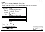


Air Handling Unit Interface
AHU-KIT-SP
MORIKAWA
CONTENTS
PSZ000Z308
1/38
MODEL NAME
MODEL TYPE
ISSUE
CLASSIFICATION
DWG NO.
REV.MARK PAGE
21.09.17
Contents
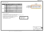
1.
Specifications .................................................................................................................................................................................................................................................. 2
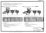
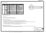
2.
System configuration ...................................................................................................................................................................................................................................... 3
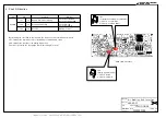
3.
Function .......................................................................................................................................................................................................................................................... 6
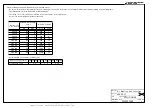
4.
Rotary switch function ..................................................................................................................................................................................................................................... 8
5.
DIP switch function ......................................................................................................................................................................................................................................... 9
6.
Short PIN function ......................................................................................................................................................................................................................................... 10
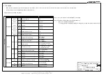
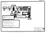
7.
Input/output circuit ......................................................................................................................................................................................................................................... 11
7.1
Input circuit ............................................................................................................................................................................................................................................... 12
7.2
Output circuit ............................................................................................................................................................................................................................................ 16
7.3
Input/output circuit .................................................................................................................................................................................................................................... 16
8.
Cascade control ............................................................................................................................................................................................................................................ 17
9.
Rotation control ............................................................................................................................................................................................................................................. 18
10.
Fault backup control ...................................................................................................................................................................................................................................... 19
11.
Modbus communication ................................................................................................................................................................................................................................ 20
12.
Protection control .......................................................................................................................................................................................................................................... 32
13.
Error display .................................................................................................................................................................................................................................................. 34
14.
Installation work ............................................................................................................................................................................................................................................ 35
15.
Wiring procedure ........................................................................................................................................................................................................................................... 37
16.
External dimensions ...................................................................................................................................................................................................................................... 38


