


Mitsubishi Programmable Logic Controller
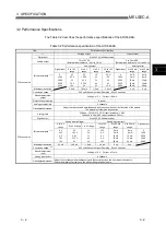
Analog Input/Output Module Type A1S66ADA
User
,
s Manual
MODEL
MODEL
CODE
A1S66ADA-U-E
13JL41
IB(NA)-66819-F(0410)MEE
Analog Input/Output Module Type A1S66ADA
User
,
s Manual
Specifications subject to change without notice.
When exported from Japan, this manual does not require application to the
Ministry of Economy, Trade and Industry for service transaction permission.
HEAD OFFICE : 1-8-12, OFFICE TOWER Z 14F HARUMI CHUO-KU 104-6212,JAPAN
NAGOYA WORKS : 1-14 , YADA-MINAMI 5-CHOME , HIGASHI-KU, NAGOYA , JAPAN
Summary of Contents for A1S66ADA
Page 2: ......
Page 13: ...2 2 2 2 MELSEC A 2 SYSTEM CONFIGURATION 2 MEMO ...
Page 44: ...6 2 6 2 MELSEC A 6 TROUBLESHOOTING 6 MEMO ...
Page 51: ......


