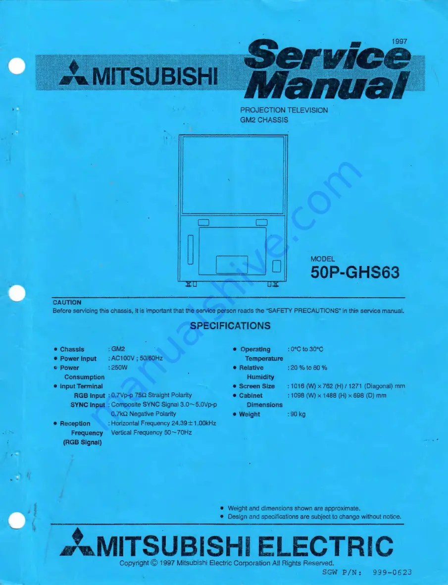
background image

Summary of Contents for 50P-GHS63

Page 1: ...SYNC Input Composite SYNC Signai3 0 5 0Vp p 0 kn Negative Polarity Reception Horizontal Frequency 24 39 1 00kHz Frequency Vertical Freq Jency 50 70Hz RGB Signal Operating Temperature Relative Humidity Screen Size Cabinet Dimensions Weight 20 to80 1016 W x 762 H 1271 Diagonal mm 1098 W x 1488 H x 698 D mm 90 kg Weight and dimensions shown are approximate Design and specifications are subject to cha...

Page 2: ...NS AND ADJUSTMENT ITEMS 11 SETTING THE USER MODE 14 SETTING THE OPTION MENU 14 ELECTRICAL ADJUSTMENTS 15 LOCATION OF TEST POINTS AND ADJUSTMENTS 16 ADJUSTMENT PROCEDURES 18 DEFLECTION CIRCUIT 18 HIGH VOLTAGE CIRCUIT 18 CRT CIRCUIT 19 DEFLECTION CIRCUIT 20 CRT CIRCUIT 22 DEFLECTION CIRCUIT 24 CONVERGENCE CIRCUIT 27 SCREEN CHARACTER CIRCUIT 31 CRT CIRCUIT 32 PARTS LIST 33 REPACKING PROCEDURE 33 ELEC...

Page 3: ...g methods 1 Cold Check With the AC plug removed from the AC source place a jumper across the two AC plug prongs Turn the receiver AC switch on Using an ohm meter connect one lead to the AC plug and touch the other lead to each exposed metal part antennas handle bracket metal cabinet screwheads metal overlays control shafts etc particularly any exposed metal part having a return path to the chassis...

Page 4: ...tention not to touch the surface of the lens by hand or damage it Cleaning Please wipe it lightly with a soft cloth When the screen is very dirty please soak a soft cloth into a diluted mild detergent Wipe it and finish cleaning with a dry cloth Wipe the lenticular screen along the streak Clean the Fresnel Lens and Mirror or Lens with a cleaner effective for prevention of static electricity 1 DEW ...

Page 5: ...TION I PCB SENSOR RIGHT PCB CRT R PCB CRT G PCB CRT B I I I I I I I l_ PCB CONV SUB _ PCB VIDEO PCB MAIN Fig 1 3 PCB SENSOR LEFT PCB SENSOR BOTTOM PCB PREAMP PCB TERMINAL PCB DEFL PCB AFC PCB SYSCON PCB POWER SUB ...

Page 6: ...Cabinet Assy Screen Assy Option Board Rear Cover L Rear Cover Assy Mirror Board Handle Board Rear Cover R Parts Name Number of Screws Screen Assy 2 Front Board 2 Fig 2 Back Cover 10 Rear Cover Assy 8 Handle Board 4 Mirror Board 4 Option Board 2 Mirror 4 Rear Cover L 4 Rear Cover R 4 4 ...

Page 7: ...ength applied to the caps If the route of the Anode Lead Wires are changed return them to the initial route Clamp the Lead Wires along the clamping zone with mark shown in the figure below Take care so that the Lead Wires are not slack 2C Optical Unit Focus Pack Clamping Zone Hidden Clamping Zone Aerial Clamp Clamping Zone shows the route of the Lead Wire bundle the High Voltage Lead Wire and the ...

Page 8: ...igh humidity causes deformation of the Lenticular Screen and Fresnel Lens Removal of the Lenticular Screen and Fresnel Lens 1 Remove 8 screws retaining the Screen Frame 2 Remove the Lenticular Screen Fresnel Lens and Monitor Glass Fig 4 1 Warm the connection portion between the Lenticular Screen and Fresnel Lens with a dryer etc and remove the Double Coated Tape Fig 4 2 Screen Frame Top Screen Fra...

Page 9: ...cover the back side 3 Insert the Monitor Glass into the Screen Frame Fig 4 4 4 Insert the Lenticular Screen and Fresnel Lens into the Screen Frame 5 1nstall8 screws retaining the Screen Frame Fig 4 1 Double Coated Tape I __ _ _ _____ Cushion Fresnel Lens Lenticular Screen Fig 4 2 Screen Frame Top Double Coated Tape I Rear Side I IFront Side I Monitor Glass Lenticular Screen Fresnel Lens Cushion Sc...

Page 10: ...etaining the Optical Unit Fig 5 2 PCB DBF Radiator for Transistor f PCB MAIN PCB POWER SUB Fig S 1 LENS B LENS G LENS R Front Rear Fig 5 2 5 Remove 4 screws retaining the Lens while supporting the CRT Fig 5 2 6 Remove 4 screws retaining the CRT while supporting the CRT Fig 5 3 _j The CRT is removable from the Optical Unit in this condition Note Never loosen the colored screws and screws with sprin...

Page 11: ...g 5 2 5 Install the PCB CRTs 4 Install the Deflection York in place Fig 5 4 6 Insert the Optical Unit into the Cabinet Fig 5 2 Focus Magnet Assy Convergence Purity Assy Green only 72mm Fig 5 4 CRT Adjustment procedures after replacing the CRT After replacing the CRT perform the following adjustments 1 Cut Off Adjustment 2 Centering Adjustment 3 Focus Adjustment 4 Ellipticity Adjustment 5 White I B...

Page 12: ... next select the adjustment item 1 Press the R 8 button to select an adjustment function Each time the button is pressed the adjustment function changes as follows rHOUR TIMER CONV ATC HR DAC J 2 Press the A or T button on the remote hand unit to select a specific adjustment item 0 Press the A button The adjustment Item Number will increase 0 Press the Y button The adjustment Item Number will decr...

Page 13: ... Horizontal Side Linearity L 0 254 127 12 72 132 HSDR Horizontal Side Linearity R 0 254 127 13 73 133 HISL Horizontal Inside Linearity 0 254 127 14 74 134 HCNL Horizontal Left Pin Correction 0 254 127 15 75 135 HCNR Horizontal Right Pin Correction 0 254 127 16 76 136 VCNL Vertical Left Pin Correction 0 254 127 17 77 137 VCNR Vertical Right Pin Correction 0 254 127 18 78 138 HKLT Horizontal Keyston...

Page 14: ...ressing A or T button on the remote hand unit Select the color using R G B button Set the data in shown below pressing 4 or button After finishing the set up write the data into memory by pressing ENTER Press the TEST button on the remote hand unit to terminate the adjustment mode Correction Coefficient Color Item Item RED GREEN BLUE ALL H HWID 0 0 V VKLT H HUN 87 52 36 v VKLB H VKLT 0 0 0 V VKRB ...

Page 15: ...ull 0 254 127 50 110 170 V42 Vertical Seagull Balance 0 254 127 51 111 171 V51 X5Y1 0 254 127 Note 1 The contents of the adjustments in indicate operation in full colors Note 2 The contents of the adjustment No in indicate that the operation is impossible Function Display ATC No Abbreviated Adjustment Name Range Data Note R G B Name 0 6 HSTA Horizontal Static 50 50 0 1 7 VSTA Vertical Static 50 50...

Page 16: ...127 127 0 H WIDTH H WIDTH 127 127 0 V POSI V POSI 127 127 0 V WIDTH V WIDTH 127 127 0 AUTO CONV AUTO CONV User Mode Display l CONTRAST 0 J Adjustment Name Adjustment Data ISETTING UP THE OPTION MENU I _ 1 Press the TEST button on the remote hand unit to change to the Option Menu The built in cross hair test pattern will appear 2 Press the 1 1 and 9 on the remote hand unit in that order to display ...

Page 17: ...l M Full White Raster 24 39 57 52 41 00 424 3 00 4 4 38 26 30 751381 2 87 13 17 Standard Signal 0 Gray Scale 24 39 57 52 41 00 424 3 00 4 4 38 26 30 751381 2 87113 18 Standard Signal P Full Black 24 39 57 52 41 00 424 3 0014 4 38126 30 75 381 2 87113 21 Standard Signal Q OPTION2 31 67 60 32 31 58 525 3 58 2 1 71150 25 88 448 0 41125 22 Standard Signal R Crosshatch with circle 31 67 60 32 31 581525...

Page 18: ... LOCATION OF TEST POINTS AND ADJUSTMENTS PCB DEFL Component side VR501 PCB AFC Component side TPGND TP2H TP1H T502 Front View VR5C1 CID 16 4 2 0 1 OoR DS 1 Front View ...

Page 19: ...PCB CRT G Component side TP GNO ffiJ VR6GO TP G PCB CRT R Component side ffiJ VR6RO PCB CRT B Component side ffiJ VR6BO PCB DEFL V Component side ffi VR452 ffi VR451 lr 1 c4 s 1 17 ...

Page 20: ...o turn the power on 5 Adjust VR5C1 with no signal supplied so that the frequency counter is 24 39 0 01kHz High voltage Circuit 2 High Voltage Control Adjustment Set high voltage to be applied to the CRT Measuring Instrument Test Point External Trigger Measurement Range Input Signal purpose Symptom when incorrectly adjusted Too widened or narrowed picture or too bright or dark picture DC Voltmeter ...

Page 21: ...the picture will return to the normal picture Select the BRIGHT adjustment mode in the User Mode Q Set the initial data of BRIGHTNESS to 0 Center value or button 5 Turn the Cut Off controls VR6RO VR6GO VR6BO clockwise fully while obseNing from the parts side 6 ObseNe the waveform at the test point TP G Use TP GND for GND 7 Set to the TEST 1 1 8 mode Press the 1 1 and 8 to activate the TEST 1 1 8 m...

Page 22: ...C or button HLIN adjusts only G Green 9 Select the item VBOW so that Line B in Fig 2 is straight Adjust G Green only 10 Keep pressing the RIB button to select the DAC adjustment mode again 11 Adjust the V POSI so that the top and bottom edges of the picture shown in Fig 2 do not disappear and the picture is positioned almost at the center IC or button 12 Select the H POSI and adjust so as not to p...

Page 23: ...n the DAC adjustment mode respectively 9 Perform adjustments so that the center of the picture is at the screen center C or button Note The position of the screen center should be 453mm away from the Top Board of the product and 570mm away from the Side Board 10 Adjust the H WIDTH and HLIN in the DAC adjustment mode of the TEST 1 1 8 mode so that A point in Fig 1 is overlapped with the left and ri...

Page 24: ... Green and B Blue tube side Lens with Lens caps to produce a Red monochrome picture Input Terminal Mini D SUB 15 Pin InputTerminal 6 Adjust Red on the FOCUS controls in the same manner as the step 4 7 Cover the tube side Lens of the Red and Green CRTs to produce a Blue monochrome picture 8 Adjust 8 Blue on the FOCUS controls in the same manner as shown in the step 4 9 Turn each front Lens of Green...

Page 25: ...r to B in the chart below Regard lhe luminescent spot as triangular circle and judge lhe vertex direction CD Open the 6 Pole Magnet on 2 sheets of the Focus Magnet at 60 o Maximum magnetism Rotate the 6 Pole Magnet while retaining the condition in step CD so that the triangular circle in step e is seen to rotate by 180 Refer to C shown in the chart below Clj Make catches for 2 sheets of 6 Pole Mag...

Page 26: ...e current value PCB DEFL Component side Note Confirm that the internal resistance of the DC Ampere Meter is 30Q or less and the length of the lead wire is 30 em or less Adjust the item 1 SUB CONT so that the current value is 71 0 I A T502 _ or BUTTON jj After adjustment press ENTER to write the data into memory CD Press the TEST button to terminate the TEST 1 1 8 mode ORo 3 Remove the DC Ampere Me...

Page 27: ...ter Input Terminal Mini D SUB 15 Pin lnpu Terminal 6 Select the item 2 HPCC SI DE PCC and perform adjustments so that the vertical lines on the left and right edges of the crosshatch are straight 7 Select the item 62 VPCC T 8 PCC and perform adjustments so that the horizontal lines at the top and bottom edges of the crosshatch are straight 8 Select the item 89 H11 and perform adjustments so that t...

Page 28: ...1 and 110 V42 V22 V41 _ 12 Unless the vertical lines and horizontal lines from the inner side are straight adjust the adjustment items 98 H32 and 1 07 V23 I I I I I H32 V23 13 Repeat the adjustments in the steps 5 to 12 if necessary 14 Press ENTER to write the data into memory 15 Press the TEST button to terminate the TEST 1 1 8 mode 26 ...

Page 29: ... Pin Input Terminal 5 Supply a Crosshatch signal No 13 6 Press the R and B buttons to produce a Green monochrome picture 7 Confirm the display concerning the following items Perform adjustments if required Green Item Note Range of adjustment data 63 TILT Horizontal Tilt 64 BOW Horizontal Bow 67 SKEW Skew 68 VBOW Vertical Bow 70 HUN Horizontal Linearity 73 HISL Horizontal Inside Linearity 2 74 HCNL...

Page 30: ...t Pin Correction Merge and iow rrightvertX allines v ilh Green lines Vertical Left Pin Correction MergelW6 ard iow rklfttaizontal lines v ilh Green lines Vertical Right Pin Correction Merge ardiow r ramtallresv ilhGreenires Horizontal Keystone Left Top Merge upper left vertical line with Green line Horizontal Keystone Left Bottom Merge lower left vertical line with Green line Horizontal Keystone R...

Page 31: ... VLIN 19 HKLB 15 HCNR 79 HKLB 75 HCNR 126 VLIN 139 HKLB 135 HCNR I I 7 SKEW 20 HKRB 16 VCNL 67 SKEW 80 HKRB 76 VCNL 27 SKEW I 140 HKRB 136 VCNL I I I I I I I I I 8VBOW I 21 HKRT I I 17VCNR 68 VBOW 81 HKRT 77VCNR r28 VBOW I I 141 HKRT 137 VCNR I I 9 HWID l 22 VKLT 45 V21 82 VKLT 105 V21 129 HWID 142 VKLT 165 V21 i l 10 HUN 23 VKLB 13 HISL 70 HUN 83 VKLB 73 HISL 130 HUN 143 VKLB 133 HISL f f Continu...

Page 32: ... I I I I 93 H16 I 100 H51 153 H16 I I 160 H51 I I I I I I I I I I I I I I I I I 36 H23 I I I I 41 V03 I I 96 H23 101 V03 156 H23 I I I I 161 V03 I I I I I I I 37 H30 I I I I 44 V13 97 H30 I I 104 V13 I I 157 H30 I I 164 V13 I I I I I I 39 H42 I I 51 V51 I 99 H42 111 V51 159 H42 171 V51 Note Refer to the adjustment 9 Raster Distortion as to the adjustments on the display except the above 30 ...

Page 33: ...utton on the remote hand unit press the 1 1 8 in that order to activate the TEST 1 1 8 mode 3 Keep pressing the R 8 button to select the HR adjustment mode 4 Perform adjustments so that A B C and D shown in the figure below are equal or button 5 Press ENTER to write the data into memory Input Signal VG 814 No 13 Crosshatch 6 Press the TEST button to terminate the TEST 1 1 8 mode Input Terminal Min...

Page 34: ...No 13 Crosshatch Input Terminal Mini SUB 15 Pin lnputTerminal 2 4 6 Pole Magnet The position where the catches are overlapped is the minimum in the magnetic field Fig 1 3 Turn the Focus controls of VA FOCUS to repeat the halo turn left wise and blooming turn right wise Note The VA FOCUS is installed at the left bottom of the screen observing from the front 4 Observe the middle of the crosshatch si...

Page 35: ...IPARTS LIST I REPACKING PROCEDURE 33 ...

Page 36: ......

Page 37: ......

Page 38: ......

Page 39: ......

Page 40: ......

Page 41: ......

Page 42: ......

Page 43: ...SEGA ENTERPRISES INC USA 45133 Industrial Drive Fremont CA 94538 650 802 1750 phone 650 802 1754 fax ...

Page 44: ...APP MINNESOTA H 9549 PENN AVE S I p T BLOOMINGTON MN 55431 0 USA ORDER NO ORDER CUSTOMER SLSMN PURCHASE ORDER SHIP VIA SHIP DATE NO NO NO DATE TERMS 1379952 07 29 09 8 928 Dave P PICK UAPdd 08 04 09 C O D repay QTYOPEN 1 QTY SHIPPED QTY BACK ITEM NO ORO 0 999 0623 Sega Amusements USA ITEM DESCRIPTION manual for Mitsubishi 50 TV Item 999 0623 MANUAL 50PGHS63 81 W SCHMTC 1111111111 9990623 UNIT PRIC...

Reviews: