background image

User's Manual

GT15-J61BT13

Thank you for choosing Mitsubishi Electric Graphic Operation Termi-
nal (GOT).

  GOT2000/GOT1000 Series

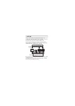
CC-Link Communication

Unit

Prior to use, please read both this manual and detailed manual 
thoroughly to fully understand the product.

MODEL

GT15-J61BT13-U

MODEL

CODE

1D7M57

IB(NA)-0800351-J(1704)MEE

Summary of Contents for 1D7M57

Page 1: ...i Electric Graphic Operation Termi nal GOT GOT2000 GOT1000 Series CC Link Communication Unit Prior to use please read both this manual and detailed manual thoroughly to fully understand the product MODEL GT15 J61BT13 U MODEL CODE 1D7M57 IB NA 0800351 J 1704 MEE ...

Page 2: ...ions are ranked as WARNING and CAUTION Note that the CAUTION level may lead to a serious accident according to the circumstances Always follow the precautions of both levels because they are important to personal safety Please save this manual to make it accessible when required and always forward it to the end user Indicates that incorrect handling may cause hazardous conditions resulting in deat...

Page 3: ...em assume that a GOT communication error will occur and configure a system in which switches used to perform significant operation for the system are provided on any device other than the GOT Not doing so can cause an accident due to mis output or misoperation Do not bunch the control wires or communication cables with the main circuit or power wires or lay them close to each other As a guide sepa...

Page 4: ...ases of the external power supply used by the system before wiring Not doing so can cause an electric shock product damage or misoperation Connect the connectors to the unit securely Always ground the FG terminal of the GOT power supply and the FG termial of this unit to the protective ground conducter Be sure to ground the GOT and this unit separately Not doing so may cause an electric shock or m...

Page 5: ...tion due to cable contact fault Do not install the control lines together with the communication cables or bring them close to each other Failure to do so may cause malfunctions due to noise When disconnecting a communication or power supply cable from the unit do not pull on the cable itself Disconnect cables fitted with connectors by holding and pulling the cable connector Disconnect cables not ...

Page 6: ...op short circuit or misoperation due to damaged screws or unit Do not disassemble or modify the unit Doing so can cause a failure misoperation injury or fire Do not touch the conductive areas and electronic parts of the unit Doing so can cause the unit to misoperate or fail Do not drop the unit or subject it to strong impact Doing so can damage the unit Always make sure to touch the grounded metal...

Page 7: ...s Failure to do so may cause the unit to fail Check if the unit operates correctly after transportation When fumigants that contain halogen materials such as fluorine chlorine bromine and iodine are used for disinfecting and protecting wooden packaging from insects they cause malfunction when entering our products Please take necessary precautions to ensure that remaining materials from fumigant d...

Page 8: ...ance with the EMC and Low Voltage Directives Jun 2011 IB NA 0800351 F Partial corrections Chapter 4 Partial addition Compliance with the Radio Waves Act South Korea Oct 2014 IB NA 0800351 G Partial corrections SAFETY PRECAUTIONS Chapter 4 5 May 2015 IB NA 0800351 H Partial corrections Cover Oct 2016 IB NA 0800351 I Partial corrections Compliance with the RoHS Apr 2017 IB NA 0800351 J Partial corre...

Page 9: ...ocket 4 3 I O SIGNALS AND REMOTE REGISTER ASSIGNMENT 5 3 1 I O Signals Transferred to from the Master Module 5 3 2 Remote Register Assignment 7 4 PART NAMES AND EXTERNAL DIMENSIONS 8 5 INSTALLATION PROCEDURE 11 5 1 CC Link communication unit installation 11 5 2 Terminal block socket installation 13 6 WIRING METHOD 14 ...

Page 10: ...te of the GOT Manual The following shows manuals relevant to this product For relevant manuals refer to the PDF manuals stored in the DVD ROM for the drawing software used Detailed Manuals Manual name Manual number Model code GOT2000 Series User s Manual Hardware Sold separately SH 081194ENG 1D7MJ5 GOT2000 Series Connection Manual Mitsubishi Products For GT Works3 Version1 Sold separately SH 08119...

Page 11: ...ompatible CC Link dedicated high performance cable Note This symbol mark is for China only 部件名称 有害物质 铅 Pb 汞 Hg 镉 Cd 六价铬 Cr VI 多溴联苯 PBB 多溴二苯醚 PBDE 电路板组件 树脂壳体 电缆 膜材 钣金部件 螺丝等金属部件 Model Product Quantity GT15 J61BT13 CC Link communication unit 1 Mounting screw set 2 screws 2 stickers 2 Extension interface relay board 1 Terminating resistor 110 1 2W brown brown brown 1 Plate type solderless terminal set...

Page 12: ...rom 1 station 4 stations in the CC Link system When using the CC Link connection make the communication setting to perform communication with PLCs For the details of the CC Link connection refer to the GOT2000 or GOT1000 Series Connection Manual Mitsubishi Products The PLC CPU on the Master local station of the CC Link system can be monitored Monitoring by Transient Transmission Intelligent device...

Page 13: ...igent device station Number of occupied stations May be selected between 1 and 4 Maximum number of link points per system Ver 2 mode Remote I O RX RY 2 8192 points Remote register RWw 2048 points Remote register RWr 2048 points Ver 1 mode Remote I O RX RY 2 2048 points Remote register RWw 256 points Remote register RWr 256 points Number of link points per station Refer to 3 Number of link points p...

Page 14: ...points Remote register RWw 4 points Remote register RWr 4 points Link device Number of link points per station Extension cyclic setting Single Double Quadruple Octuple 1 station occup ied 4 station occup ied 1 station occup ied 4 station occup ied 1 station occup ied 4 station occup ied 1 station occup ied 4 station occup ied Remote I O RX RY 32 points 128 points 32 points 224 points 64 points 448...

Page 15: ...ons of terminal block socket Item Specifications Screw tightening torgue Wiring screw Terminal block fixing screw 0 5 to 0 6 N m 0 7 to 0 8 N m Recommended driver Flat blade screwdriver Blade thickness 0 6mm Width 3 5mm ...

Page 16: ...RX n C F User area RX n 1 0 to RX n 1 A RX n 7 0 to RX n 7 A RX n 1 0 to RX n 1 A RX n D 0 to RX n D A Reserved RX n 1 B RX n 7 B RX n 1 B RX n D B Remote READY flag 2 RX n 1 C to RX n 1 F RX n 7 C to RX n 7 F RX n 1 C to RX n 1 F RX n D C to RX n D F Reserved Signal Direction GOT Master module Device No Signal name Extension cyclic setting 1 Quadruple Octuple 1 station occupied 4 station occupied...

Page 17: ...CC Link Master station Signal Direction GOT Master module Device No Signal name Extension cyclic setting 1 Single Double 1 station occupied 4 station occupied 1 station occupied 4 station occupied RYn0 to RYnF RYn0 to RY n 6 F RYn0 to RYnF RYn0 to RY n C F User area RY n 1 0 to RY n 1 F RY n 7 0 to RY n 7 F RY n 1 0 to RY n 1 F RY n D 0 to RY n D F Reserved Signal Direction GOT Master module Devic...

Page 18: ...ension cyclic setting 3 Single Double 1 station occupied 4 station occupied 1 station occupied 4 station occupied Master station GOT RWwm to RWwm 3 RWwm to RWwm F RWwm to RWwm 7 RWwm to RWwm 1F User wirte area 0 GOT Master station RWrn to RWrn 3 RWrn to RWrn F RWrn to RWrn 7 RWrn to RWrn 1F User read area 0 Transfer Direction Address Description Default Value Extension cyclic setting 3 Quadruple O...

Page 19: ...3 0 91 Unit mm inch No Name Description 1 CC Link communication connector Connector for connecting the CC Link dedicated cable 2 Interface connector Extension connector installed to a front extension unit or the GOT 3 Extension connector Extension connector to which a back extension unit is installed 4 Mounting screw Mounting screws fixed with a front extension unit or the GOT 133 5 24 3 0 12 2 5 ...

Page 20: ... mode restart the GOT If the error mode is not released after restarting the GOT the system alarm 460 Communication unit error may have occurred For system alarms refer to the User s Manual for the GOT used No Name Description ERR RD RUN SD LED name Status Details RUN OFF The GOT is being reset ON The unit is in a normal status ERR OFF The unit is in a normal status ON The communication statues of...

Page 21: ...10 Extension interface relay board Unit mm inch 64 2 52 24 0 94 27 5 1 08 ...

Page 22: ...t covers of the GOT 3 Attach the extend interface relay board to the extend I F 2 side on the GOT After the installation detach the connector cover from the extend interface relay board For the following GOT types the extension interface relay board is not needed GT1655 155 of the GOT1000 series GT27 GT25 of the GOT2000 series 4 Fit the CC Link communication unit in the GOT case 4 3 Remove the con...

Page 23: ... the unit that has been installed remove the connector cover and the sticker When not installing an extension unit on the unit that has been installed in order to avoid receiving electrostatic stick accessory stickers to cover the top of mounting screws 4 places Keep the connector cover fixed Keep the sticker stuck as it is POINT Remove the screws that fixes the extension interface relay board bef...

Page 24: ...es or cables by ducts or clamps when connecting them to the unit Not doing so can damage the unit or cables due to dangling moved or accidentally pulled cables or can cause misoperation due to cable contact fault POINT When attaching or removing a communication cable to from the terminal block socket detach the terminal block socket from the connector When extension units are installed in multiple...

Page 25: ...n the same color together When connecting the braid shields of the CC Link dedicated cables of the previous station and the next station caulk each braid shield to the supplied solderless terminal Plate type then insert the shields into the terminal block socket DA DB DG SLD FG DA DB DG SLD FG DA DB DG SLD FG GOT Blue Yellow White Master module I O module etc Terminal resistor CC Link dedicated ca...

Page 26: ...ule or the CC Link com munication unit must be connected to the PLC module or GOT at both ends of the data link Connect them across DA DB Connect the shield wire of the CC Link dedicated cable to SLD of each module Since SLD is connected to FG internally always ground the FG terminal and FG1 terminal to the protective ground conductor The FG terminal of the GOT power supply and the FG terminal of ...

Page 27: ...16 MEMO ...

Page 28: ... Direzionale Colleoni Palazzo Sirio Viale Colleoni 7 Agrate Brianza MB Italy Tel 39 039 60531 Mitsubishi Electric Europe B V Spanish Branch Carretera de Rubi 76 80 Apdo 420 08190 Sant Cugat del Valles Barcelona Spain Tel 34 935 65 3131 Mitsubishi Electric Europe B V French Branch 25 Boulevard des Bouvets 92741 Nanterre Cedex France Tel 33 1 55 68 55 68 Mitsubishi Electric Europe B V Czech Branch A...

Reviews: