background image

Installation Instructions

F 1813 SF, F 1913 SF

           en - CA 


Installation, repair and maintenance work should be performed by 
a Miele authorized service technician in accordance with national 
and local safety regulations and the provided installation instructions.

Summary of Contents for F 1813 SF

Page 1: ...F 1813 SF F 1913 SF en CA Installation repair and maintenance work should be performed by a Miele authorized service technician in accordance with national and local safety regulations and the provided installation instructions ...

Page 2: ...terials that can be recycled Please contract your local recycling authority about the possibility of recycling these materials Instead please contact your municipality s waste collection center to return and recycle electric and electronic appliances Please take care not to damage the pipework while the appliance is being stored for transport to a waste disposal facility By protecting the pipework...

Page 3: ...temperature in the appliance to rise with the risk of food deteriorating and going off Installation site The appliance should be installed in a dry well ventilated room Do not install the appliance outdoors in an environment with dripping water in rooms that are at risk of frost The installation location should not be exposed to direct sunlight nor near a heat source such as an oven radiator etc T...

Page 4: ...nditioned room with sufficient ventilation Please ensure that doors close and seal properly after installation and that the appliance is installed in accordance with these installation instructions and and with the required ventilation openings If the room is too cold it will cause the cooling system in the appliance to remain off for too long This can cause the temperature in the appliance to ris...

Page 5: ...n it is essential that all attachable furniture fixtures be connected securely to the floor or wall by a suitable means Ventilation The air intake and outlet must not be blocked or covered in any way They also need to be dusted cleaned on a regular basis Installation niche To ensure safe trouble free installation and the best possible cosmetic result check to be sure that the installation space co...

Page 6: ...by side This appliance can be installed side by side with another fridge freezer using a Merging Kit The Merging Kit is available from Miele Contact Miele or your dealer for specific information about which combinations will work with your appliance For instructions on how to attach the appliances and install the heating mat please refer to the instructions included with the Merging Kit available ...

Page 7: ...f there is a partition with a thickness of more than 6 5 16 160 mm between the adjacent appliances then each appliance should be individually installed within its own niche using the mounting accessories included the Merging Kit is not necessary Side panels If one side of the appliance is visible a side panel must be used The side panel must be firmly secured to the wall the floor and the overhead...

Page 8: ...Door dimensions open 115 A B F 18X3 SF 32 5 8 829 mm 14 5 16 363 mm F 19X3 SF 38 11 16 982 mm 16 7 8 428 mm Miele recommends using the full door opening angle of 115 for this freezer Dimensions 52 ...

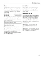
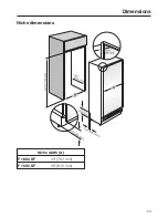
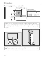
Page 9: ...Niche dimensions Niche width A F 18X3 SF 30 762 mm F 19X3 SF 36 915 mm Dimensions 53 ...

Page 10: ...ng device and water hammer arrester for inlet water pressures exceeding 80 psi Refer to Uniform Plumbing Code Sections 608 2 and 609 10 Never install or operate where inlet water pressure may exceed 120 psi Power bars or extension cords are not safe risk of fire Do not use them to connect the appliance to the power supply Dimensions 54 ...

Page 11: ... or local codes In Canada the Canadian Electric code C22 1 latest edition Provincial and Municipal codes and or local codes Tools needed for installation Cutter with adjustable blade Cordless screwdriver T 20 Torx screwdriver T 20 Hammer drill for drilling holes in wall or floor Wood drills in different sizes Hammer Open ended wrench SW 13 mm Box end wrench 5 16 8 mm hex nut driver Adhesive tape M...

Page 12: ...ce complies with the installation requirements Check the base see Installation Check the dimensions of the cavity Check that the cavity is square Check the location of the power outlet Check the location of the water connection see Plumbing Check that all furniture parts in the vicinity of the appliance are securely connected to the wall Check that the adjacent furniture fixtures do not collide wi...

Page 13: ... appliance carefully lift it from the pallet Once the appliance is on the ground it can be wheeled around RemoteVision module installation optional accessory Always disconnect the appliance from the power supply when performing installation maintenance or service work Install the RemoteVision module before placing the appliance in its installation niche Once connected the RemoteVision module will ...

Page 14: ... that case repeat the process If that does not correct the problem contact Miele Pull the antenna d straight out Guide the cover b over the antenna d and screw on the cover Angle the antenna d so that it faces to the right or left If necessary disconnect the power supply and continue installing the appliance Preparing the installation niche Keep the appliance door closed until it is securely faste...

Page 15: ...anti tip brackets are recommended for each appliance For side by side installations 4 brackets are recommended Position the anti tip brackets on the left and right in the installation niche so that there is no more than 3 8 10 mm of space between the brackets and the side walls Mark the drill holes in the anti tip brackets on the back wall and on the ceiling of the installation niche Set the brack...

Page 16: ...w the back wall of the cabinet in several places directly to the wall behind it For this use suitable plugs screws depending on the type of wall In a cabinet without a back wall screw the cabinet to the wall behind it in several places using suitable mounting brackets For this use suitable plugs screws depending on the type of wall Installing the appliance 60 ...

Page 17: ...st cover the appliance by at least 2 50 8 mm Mark the installation height lower edge of the beam on the rear wall of the niche Select screws according to the thickness of the wooden beam Example 3 screw for 2x4 beam Determine the number of screws based on the cavity width to ensure that the beam will be attached securely Locate wall studs near the rear wall of the cavity and mark drill holes in th...

Page 18: ...be completed via the circuit breaker In the case of side by side installations a separate outlet must be used for each appliance To prevent the power cord from becoming caught Tie a piece of string to the middle of the power cord and feed it forward under the appliance When sliding the appliance in pull the cable forward b Carefully slide the appliance into the space If resistance is felt when att...

Page 19: ...he height adjustable feet until the mark on the base has reached the indicated guide dimension 1 1 4 32 mm The guide dimension of 1 1 4 32 mm is related to a niche height of 84 2134 mm Align the appliance again using a level If using a wooden beam as an alternative anti tip device rotate the appliance all the way toward the wooden beam Note Do not twist or jam the appliance inside the niche When u...

Page 20: ...ctly and place it in the gap Now connect the water supply to the appliance see Plumbing Attaching the toe kick cover The maximum height of the toe kick cover is 4 from the top of the floor Do not cover the ventilation slits in the plinth Risk of damage to the appliance If required cut the toe kick cover to the required length and height Attach the plinth to the appliance Put the included cover pla...

Page 21: ...his prevents warm exhaust air from flowing into the machine optimizing the energy performance of the unit If necessary shorten the three parts of the air separator Insert the foam pieces back into the sides Position the air separator in the center of the appliance door From below screw the air separator firmly onto the door with the 2 screws Installing the appliance 65 ...

Page 22: ... for connection to the cold water supply The water pressure must be between 25 and 80 psi 1 7 5 5 bar A separate shut off valve must be installed so that the water supply can be interrupted as needed The maximum outer diameter of the water pipe without fittings 3 8 10 mm The shut off valve for the water connection must not be located behind the appliance It is recommended to place the shut off val...

Page 23: ...Always observe the indicated clearance dimensions to prevent damage to the connecting pipe when pushing in the appliance Secure the connecting pipe to the floor with adhesive tape You may now proceed to install the appliance See Installing the appliance For appliances with a hose guide position the device in front of the niche and push the stainless steel tube through the hose guide at the back of...

Page 24: ...o suit the location of the connection on the appliance 2 Push the union nut and seal onto the water pipe Push the end of the water pipe into the appliance connection and screw on the union nut 3 First tighten by hand Then use an open ended wrench to tighten the union nut Do not over tighten Open the shut off valve and the main water connection Check for leaks at the connection for the shut off val...

Page 25: ...estions regarding the electrical connection of this appliance to the power supply please consult a licensed electrician or call the Miele Technical Service U1 800 999 1360 V1 800 565 6435 The appliance is supplied with a UL listed 3 wire power cord and NEMA 5 15 P plug ready for connection to a 120 V 60 Hz supply The fuse rating is 15 amps The appliance requires a 3 wire receptacle The receptacle ...

Page 26: ...stallation section of this manual Be sure your wireless system meets the following requirements A wireless router that supports an IEEE 802 11b g protocol Windows XP or newer operating system Mac OS X 10 3 or higher Cable or DSL modem Microsoft Internet Explorer 6 or higher Safari 2 0 or higher Firefox 1 5 or higher Please note that each wireless router manufacturer supplies their own device drive...

Page 27: ...ess button p to confirm See the table on the following page for a description of each setting in the display Use the Y or X buttons to select the RemoteVision options The module has been connected to the network when appears in the display If does not appear refer to the Network options section of the XKM 2000 Installation Instruction manual Press and hold the access button p for 2 seconds to conf...

Page 28: ...ork established no IP address assigned Solid Connected to network Flashing In Ad Hoc Mode not connected Flashing In Ad Hoc Mode connected Selectable options Description of function Back 2 Reboot the module 3 Reset to factory settings 4 Enter Ad Hoc Mode Note If you cannot select any option other than Back the module has not been installed correctly RemoteVision optional accessory 72 ...

Page 29: ...73 ...

Page 30: ...74 ...

Page 31: ...75 ...

Page 32: ...M Nr 09 920 840 00 en US CA F 1813 SF F 1913 SF ...

Reviews: