background image

INSTRUCTION MANUAL

MANUAL DE INSTRUCCIONES

Battery Powered Wheelbarrow

Carretilla Propulsada a Batería

XUC04 

XUC05 

XUC06

IMPORTANT:

 Read Before Using.

IMPORTANTE:

 Lea antes de usar.

Summary of Contents for XUC04

Page 1: ...INSTRUCTION MANUAL MANUAL DE INSTRUCCIONES Battery Powered Wheelbarrow Carretilla Propulsada a Batería XUC04 XUC05 XUC06 IMPORTANT Read Before Using IMPORTANTE Lea antes de usar ...

Page 2: ... bucket is installed 104 106 kg 229 234 lbs Protection degree IPX4 Outer diameter when turning with front wheel as axis Due to our continuing program of research and development the specifications herein are subject to change without notice Specifications may differ from country to country The weight may differ depending on the attachment s including the battery cartridge The lightest and heavi es...

Page 3: ...ective equipment Always wear eye protection Protective equipment such as dust mask non skid safety shoes hard hat or hearing protection used for appropriate conditions will reduce personal injuries 3 Prevent unintentional starting Ensure the switch is in the off position before connecting to power source and or battery pack picking up or carrying the tool Carrying power tools with your finger on t...

Page 4: ...d repair person using only identical replacement parts This will ensure that the safety of the power tool is maintained 2 Never service damaged battery packs Service of battery packs should only be performed by the manufacturer or authorized service providers 3 Follow instruction for lubricating and chang ing accessories 4 Do not modify or attempt to repair the appli ance or the battery pack excep...

Page 5: ...lity 4 Do not operate the machine on excessively steep slopes This reduces the risk of loss of control slipping and falling which may result in personal injury Slopes greater than the maxi mum recommended grade and side grades may increase the risk of instability and may adversely affect the ability to stop safely 5 When working on slopes always be sure of your footing always work across the face ...

Page 6: ...r or bucket may be tilted and the objects fall when going downhill 11 When operating the machine near walls be careful not to get your hands caught between the handle and the wall 12 Do not use the machine in bad weather condi tions especially when there is a risk of light ning This decreases the risk of being struck by lightning 13 Use extreme caution on slippery loose and unstable terrain Wet an...

Page 7: ...r debris from the tires Install the ladder rails on a flat and stable surface 3 Before loading or unloading the machine make sure that there are no people around the machine and the ladder rails Load or unload the machine at low speed taking care to pre vent the machine from falling off the ladder rails and not to hit your head on the ceiling of the truck Use extreme caution when loading or unload...

Page 8: ... Do not allow chips dust or soil stuck into the terminals holes and grooves of the battery cartridge It may cause heating catching fire burst and malfunction of the tool or battery car tridge resulting in burns or personal injury 17 Unless the tool supports the use near high voltage electrical power lines do not use the battery cartridge near high voltage electri cal power lines It may result in a...

Page 9: ...ake lever 8 Rear wheel 9 Rear wheel lock 10 Reflector 11 Lock lever 12 Front wheel 13 Front lamp 14 Carrier XUC06 7 8 9 10 7 1 2 3 4 12 14 11 5 6 13 Fig 3 1 Control panel 2 Beep button 3 Switch trigger 4 Rear lamp 5 Reflector 6 Rear wheel lock 7 Handle 8 Battery box 9 Brake lever 10 Rear wheel 11 Front wheel 12 Front lamp 13 Cap 14 Flat bucket ...

Page 10: ... MACHINE When the bucket is installed 1 2 3 Fig 4 1 Bucket 2 Dump unit 3 Base unit When the carrier is installed 1 2 3 Fig 5 1 Carrier 2 Dump unit 3 Base unit When the flat bucket is installed 1 2 Fig 6 1 Flat bucket 2 Base unit ...

Page 11: ...lock lever 1 2 Fig 7 1 Brake lever 2 Lock lever Installing or removing the dump unit Optional accessory Installing the dump unit 1 Take out the dump unit and the handle from the box 1 2 Fig 8 1 Dump unit 2 Handle 2 Insert the pipes of the handle into the dump unit as shown in the figure and then tighten 4 bolts securely 1 2 Fig 9 1 Bolt 2 Handle NOTE When tightening the bolts lift the handle sligh...

Page 12: ...ine securely 1 2 Fig 13 1 Bolt front 2 Bolt rear 7 Attach the cord cover 1 Fig 14 1 Cord cover Removing the dump unit To remove the dump unit perform the installation proce dure in reverse Installing or removing the bucket Optional accessory Installing the bucket 1 Take out the bucket stays and front pipe from the box 1 2 3 Fig 15 1 Bucket 2 Stay 3 Front pipe 2 Insert the front pipe between the up...

Page 13: ...ghten the nut from the bottom Tighten the rest of the bolts and nuts in the same way 1 2 3 4 5 Fig 18 1 Bolt 2 Rubber washer 3 Flat washer 4 Spring washer 5 Nut 5 Securely tighten 4 bolts which were temporarily tightened in step 3 Removing the bucket To remove the bucket perform the installation proce dure in reverse Installing or removing the carrier Optional accessory Installing the carrier 1 Ta...

Page 14: ...3 Spring washer 4 Nut Removing the carrier To remove the carrier perform the installation proce dure in reverse Installing or removing the flat bucket Optional accessory Installing the flat bucket 1 Take out the flat bucket and holding frames from the box 1 2 Fig 22 1 Flat bucket 2 Holding frame 2 Assemble the holding frames by tightening 12 bolts 1 Fig 23 1 Bolt 3 Remove the cord cover located in...

Page 15: ...lling or removing battery cartridge CAUTION Always switch off the machine and lock the brake lever before installing or removing of the battery cartridge CAUTION Always install the battery cartridge fully until the red indicator cannot be seen If not it may accidentally fall out of the machine causing injury to you or someone around you CAUTION Do not install the battery cartridge forcibly If the ...

Page 16: ...rom the battery box while sliding the button on the front of the cartridge 1 Fig 32 1 Button 3 Turn the lock key counterclockwise and pull it out 4 Close the cover of the battery box Machine battery protection system The machine is equipped with a machine battery protection system This system automatically cuts off power to the motor to extend machine and battery life The machine will automaticall...

Page 17: ... switch the battery cartridges to charged ones or charge the battery cartridges If you continue to operate the machine at low battery capacity and the remaining battery capacity runs out a long beep sound is emit ted and the machine automatically stops and this may cause an accident or injury CAUTION If the beep sound is emitted while operating on slopes move the machine to a safe place lock the b...

Page 18: ...he machine uses 2 battery cartridges for operation at a time Up to 4 battery cartridges can be installed to the machine Before operating the machine select the battery cartridges used for operation by turning the battery selection switch NOTICE If the battery cartridge is in the following condition the machine does not work even if you switch the battery with the battery selection switch The remai...

Page 19: ...ile pulling the switch trigger the machine does not turn on Release the switch trigger and then press the power button Forward reverse and speed button 1 2 Fig 37 1 Forward reverse button 2 Speed button Press the forward reverse button to switch between the forward mode and reverse mode Press the speed but ton to switch between low speed medium speed and high speed When the power is turned on the ...

Page 20: ...can be adjusted within the set speed range To stop the machine release the switch trigger and pull the brake lever To lock the brake lever pull and hold the brake lever then pull the lock lever and then release the brake lever while pulling the lock lever To release the lock pull the brake lever 1 Fig 41 1 Switch trigger 1 2 Fig 42 1 Brake lever 2 Lock lever Adjusting the width of the carrier NOTI...

Page 21: ... lock You can fix the direction of the rear wheels using the rear wheel lock 1 Slightly move the machine forward so that the rear wheels face the direction shown in the figure 1 Fig 46 1 Rear wheel 2 Rotate the rear wheel lock toward the rear 1 Fig 47 1 Rear wheel lock 3 Lock the other rear wheel in the same way 4 Move the rear wheel back and forth or left and right slightly to make sure it is loc...

Page 22: ...ICE Before returning the neutral change lever lock the brake lever Make sure that the neutral change lever is fully returned as shown in the figure 1 Fig 51 1 Neutral change lever Using the level Using the level you can check if the ground is level 1 Fig 52 1 Level OPERATION CAUTION Be sure to lock the brake lever before loading unloading and dumping objects or draining liquid Operating the machin...

Page 23: ...ed CAUTION Be sure to load objects within the carrier bucket or flat bucket If objects are sticking out of the carrier bucket or flat bucket they may fall or collapse if they touch obstacles Fig 57 CAUTION Be sure to load objects so that they are below eye level If the load is too high it is dangerous because the view is obscured Also there is a risk of overturning and injury because the load is l...

Page 24: ...e dump unit CAUTION Before lifting the carrier or bucket make sure that there are no people or obstacles around the machine You can dump the objects by lifting and tilting the carrier or bucket 1 Stop the machine and then lock the brake lever NOTICE It is recommended to chock the front wheels to stabilize the machine 2 Rotate the lock lever of dump unit counterclock wise to unlock the dump unit 1 ...

Page 25: ...spections before operation the machine Check that the bolts nuts and knobs are tightened firmly Fig 63 Check that the brake is working properly If you feel the brake is not working sufficiently perform the cleaning of the brake or adjust the brake lever by referring to the section for adjusting the brake Check that the dump unit is locked when the han dle of the dump unit is fully pulled down 1 Fi...

Page 26: ...ficient refill the tire with air using an inflator The recommended tire pressure is as follows Tire for front wheel 280 kPa 40 PSI Tire for rear wheel 525 KPa 75 PSI Front wheel Fig 65 Rear wheel Fig 66 Adjusting the brake If you feel the brake is not working sufficiently adjust the brake lever 1 Pull the brake lever to release the lock of the brake lever 1 Fig 67 1 Brake lever 2 Loosen the adjust...

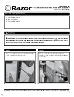
Page 27: ...27 ENGLISH 3 Tighten only the fixing nut of the brake lever 1 Fig 69 1 Fixing nut ...

Page 28: ...replacing the tires be sure to unload all objects from the machine CAUTION When replacing the tires wear the gloves Replacing the tire of front wheel NOTE When installing the gray tire install it so that the valve faces outward 1 3 5 2 4 6 Fig 70 ...

Page 29: ...29 ENGLISH Replacing the tire of rear wheel 1 3 5 2 4 6 Fig 71 ...

Page 30: ...30 ENGLISH 7 9 11 8 10 12 Fig 72 ...

Page 31: ...or locked Remove the cause of stuck or locked wheels The lamp lights up in red The machine stopped due to overheat Cool down the machine and battery The lamp blinks in red and green alternately The lock key is not inserted Insert the lock key and turn it clockwise The machine detected an abnormality Turn off the machine and then back on A malfunction of machine has occurred Ask Makita Authorized S...

Page 32: ... original position 15 Load the objects and turn on the machine OPTIONAL ACCESSORIES CAUTION These accessories or attachments are recommended for use with your Makita machine specified in this manual The use of any other accessories or attachments might present a risk of injury to persons Only use accessory or attach ment for its stated purpose CAUTION Only use the Makita accessory or attachment fo...

Page 33: ...104 kg 106 kg 229 lbs 234 lbs Grado de protección IPX4 Diámetro exterior al girar con la rueda delantera como eje Debido a nuestro continuo programa de investigación y desarrollo las especificaciones aquí incluidas están sujetas a cambio sin previo aviso Las especificaciones pueden variar de país a país El peso puede variar en función de los accesorios incluido el cartucho de batería En la tabla s...

Page 34: ...do para uso en exteriores La utilización de un cable apropiado para uso en exteriores redu cirá el riesgo de que se produzca una descarga eléctrica 6 Si no es posible evitar usar una herramienta eléctrica en condiciones húmedas utilice un alimentador protegido con interruptor de cir cuito de falla a tierra ICFT El uso de un ICFT reduce el riesgo de descarga eléctrica 7 Las herramientas eléctricas ...

Page 35: ...ramienta eléctrica para realizar operaciones distintas de las indicadas podrá presentarse una situación peligrosa 8 Mantenga los mangos y superficies de asi miento secos limpios y libres de aceite o grasa Los mangos y superficies de asimiento resbalosos no permiten una manipulación segura ni el control de la herramienta en situaciones inesperadas 9 Cuando vaya a utilizar esta herramienta evite usa...

Page 36: ...esperadamente 10 Asegúrese de que todos los tornillos de blo queo estén firmemente apretados antes del uso Los tornillos de bloqueo en las ruedas así como en la parte delantera y paredes laterales de la cesta de tipo abierta deberán asegurarse para evitar un movimiento no intencional de estas piezas ajustables de la máquina 11 Nunca opere la máquina en condiciones de sobrecarga Asegúrese de que la...

Page 37: ...o ade cuado por debajo y a ambos lados para evitar las desviaciones y los movimientos laterales bajo la carga Todas las rampas deberán ser lo suficien temente anchas para asegurar una pisada firme al acarrear las cargas a través de éstas 10 Asegúrese de que la tolva esté abajo y que las tolvas y compuertas de descarga estén bien aseguradas cuando no vaya a verter la carga y al almacenar la máquina...

Page 38: ...el límite de peso del puente y cruce el puente con cuidado a una velocidad constante 17 Porte guantes cuando haga funcionar la máquina en ambientes de temperatura baja Si toca las piezas metálicas con las manos desprote gidas puede que se le peguen las manos 18 Si hay personas u obstáculos en la dirección de desplazamiento evítelos con anticipación 19 No recoja objetos directamente con la cesta o ...

Page 39: ... y la llave de bloqueo y fije la máquina de forma segura Mantenimiento 1 Antes de almacenar o intentar realizar inspec ciones o mantenimiento siempre asegúrese de detener la máquina en un terreno plano y bloquear la palanca del freno apagar la máquina y quitar la llave de bloqueo y los cartuchos de batería GUARDE ESTAS INSTRUCCIONES ADVERTENCIA NO DEJE que la comodidad o familiaridad con el produc...

Page 40: ... batería Podría pro vocar calentamiento incendio explosión y mal funcionamiento de la herramienta o del cartucho de batería lo que resultaría en quemaduras o lesiones personales 17 No utilice el cartucho de batería cerca de cables eléctricos de alto voltaje a menos que la herramienta sea compatible con el uso cer cano a estos cables eléctricos de alto voltaje Esto podría ocasionar una avería o des...

Page 41: ...guro de la rueda trasera 10 Reflector 11 Palanca de bloqueo 12 Rueda delantera 13 Lámpara delantera 14 Cesta XUC06 7 8 9 10 7 1 2 3 4 12 14 11 5 6 13 Fig 3 1 Panel de control 2 Botón de pitido 3 Gatillo interruptor 4 Lámpara trasera 5 Reflector 6 Seguro de la rueda trasera 7 Mango 8 Caja de batería 9 Palanca del freno 10 Rueda trasera 11 Rueda delantera 12 Lámpara delantera 13 Tapón 14 Canasta pla...

Page 42: ...A Con la canasta instalada 1 2 3 Fig 4 1 Canasta 2 Unidad de vertido 3 Unidad de base Con la cesta instalada 1 2 3 Fig 5 1 Cesta 2 Unidad de vertido 3 Unidad de base Con la canasta plana instalada 1 2 Fig 6 1 Canasta plana 2 Unidad de base ...

Page 43: ... 2 Fig 7 1 Palanca del freno 2 Palanca de bloqueo Instalación o extracción de la unidad de vertido Accesorio opcional Instalación de la unidad de vertido 1 Extraiga la unidad de vertido y el mango de la caja 1 2 Fig 8 1 Unidad de vertido 2 Mango 2 Inserte los tubos del mango en la unidad de ver tido como se muestra en la figura y luego apriete los 4 pernos firmemente 1 2 Fig 9 1 Perno 2 Mango NOTA...

Page 44: ... 2 Fig 13 1 Perno delantero 2 Perno trasero 7 Coloque la cubierta del cable 1 Fig 14 1 Cubierta del cable Remoción de la unidad de vertido Para remover la unidad de vertido realice el procedi miento de instalación en orden inverso Instalación o extracción de la canasta Accesorio opcional Instalación de la canasta 1 Saque la canasta retenedores y tubo frontal de la caja 1 2 3 Fig 15 1 Canasta 2 Ret...

Page 45: ...tuerca desde la parte inferior Apriete el resto de pernos y tuercas de la misma manera 1 2 3 4 5 Fig 18 1 Perno 2 Arandela de goma 3 Arandela plana 4 Arandela de muelle 5 Tuerca 5 Apriete firmemente los 4 pernos que se apretaron provisionalmente en el paso 3 Extracción de la canasta Para extraer la canasta realice el procedimiento de instalación en orden inverso Instalación o extracción de la cest...

Page 46: ...Tuerca Extracción de la cesta Para extraer la cesta realice el procedimiento de insta lación en orden inverso Instalación o extracción de la canasta plana Accesorio opcional Instalación de la canasta plana 1 Saque la canasta plana y los marcos de sujeción de la caja 1 2 Fig 22 1 Canasta plana 2 Marco de sujeción 2 Arme los marcos de sujeción al apretar los 12 pernos 1 Fig 23 1 Perno 3 Retire la cu...

Page 47: ...ción o extracción del cartucho de batería PRECAUCIÓN Apague siempre la máquina y bloquee la palanca del freno antes de instalar o extraer el cartucho de batería PRECAUCIÓN Instale siempre el cartucho de batería por completo hasta que el indicador rojo no pueda verse Si no es así éste podría caerse de la máquina ocasio nándole una lesión a usted o a alguien más a su alrededor PRECAUCIÓN No instale ...

Page 48: ...ta de la caja de batería 1 Fig 31 1 Cubierta Extracción del cartucho de batería 1 Jale hacia arriba la palanca de bloqueo y luego abra la cubierta de la caja de batería 2 Saque el cartucho de batería de la caja de bate ría mientras desliza el botón en la parte delantera del cartucho 1 Fig 32 1 Botón 3 Gire la llave de bloqueo en sentido inverso al de las manecillas del reloj y jálela hacia afuera ...

Page 49: ...namiento 1 Apague la máquina y luego enciéndala nueva mente para reiniciarla 2 Cargue la s batería s o reemplácela s con batería s recargada s 3 Deje que la máquina y la s batería s se enfríen AVISO Si no hay mejoría en la máquina o esta se detiene debido a una causa no descrita anterior mente consulte la sección de detección y solu ción de problemas Indicación de la capacidad restante de la bater...

Page 50: ... nivel de la batería del cartucho de batería Únicamente para cartuchos de batería con el indicador 1 2 Fig 34 1 Luces indicadoras 2 Botón de verificación Oprima el botón de verificación en el cartucho de la batería para que indique la capacidad restante de la batería Las luces indicadoras se iluminarán por algu nos segundos Luces indicadoras Capacidad restante Iluminadas Apagadas Parpadeando 75 a ...

Page 51: ... problemas NOTA Si la lámpara de alimentación principal se enciende en rojo o parpadea en rojo o en verde consulte las instrucciones para ver lo referente al sistema de protección de la máquina batería o la sección de detección y solución de problemas NOTA Esta máquina emplea la función de apagado automático Para evitar un arranque accidental la máquina se apagará automáticamente cuando esta se de...

Page 52: ... del freno PRECAUCIÓN Antes de instalar el cartucho de batería en la máquina verifique siempre que el gatillo interruptor se accione debidamente y que regrese a la posición de apagado al soltarlo Para arrancar la máquina jale el gatillo interruptor Mediante el gatillo interruptor la velocidad se puede ajustar dentro del rango de velocidad establecido Para detener la máquina suelte el gatillo inter...

Page 53: ...s mangos AVISO Fije los mangos izquierdo y derecho a la misma altura La altura del mango se puede ajustar en siete niveles Para ajustar la altura del mango afloje las 2 perillas luego ajuste la altura del mango alineando el orificio del mango con la protuberancia del marco posterior y luego apriete las 2 perillas firmemente Ajuste la altura del otro mango de la misma manera 1 Fig 45 1 Perilla Segu...

Page 54: ...erentes como se muestra en la figura Fig 49 Palanca de cambio neutral ADVERTENCIA A menos que sea abso lutamente necesario nunca desactive el freno eléctrico de la máquina con la palanca de cambio neutral Dado que el freno eléctrico de la máquina está desactivado la máquina podría moverse invo luntariamente y provocar un accidente o lesiones personales ADVERTENCIA Asegúrese de devolver la palanca ...

Page 55: ...a palanca del freno antes de cargar descargar y tirar objetos o drenar líquido Operación de la máquina AVISO Asegúrese de insertar la llave de bloqueo antes de la operación Si la llave de bloqueo no es insertada se escuchará un pitido cuando jale el gatillo interruptor El pitido se detendrá al soltar el gatillo interruptor y jalar la palanca del freno AVISO Realice la inspección antes de operar la...

Page 56: ...ar los objetos dentro de la cesta canasta o canasta plana Si los objetos sobresalen de la cesta canasta o canasta plana podrían caerse o derrumbarse si tocan obstáculos Fig 57 PRECAUCIÓN Asegúrese de cargar los objetos de tal forma que queden por debajo del nivel de los ojos Si la carga es demasiado alta la vista podría taparse y resultar peligroso Asimismo podría haber riesgo de volcadura y lesio...

Page 57: ...r la cesta o la canasta asegúrese de que no haya personas ni obstáculos alrededor de la máquina Usted puede verter los objetos levantando e inclinando la cesta o canasta 1 Detenga la máquina y luego bloquee la palanca del freno AVISO Es recomendable calzar las ruedas delanteras para estabilizar la máquina 2 Gire la palanca de bloqueo de la unidad de vertido en sentido inverso al de las manecillas ...

Page 58: ...uina antes del almacena miento inspecciones o tareas de mantenimiento PRECAUCIÓN Retire siempre la llave de bloqueo cuando no vaya a utilizar la máquina Guarde la llave de bloqueo en un lugar seguro y fuera del alcance de los niños Inspección antes de la operación Inspeccione lo siguiente antes de operar la máquina Verifique que los pernos tuercas y perillas estén firmemente apretados Fig 63 Verif...

Page 59: ...e batería y la llave de bloqueo Almacene la máquina en un lugar seguro y fuera del alcance de los niños Rellenado de aire del neumático Verifique que al neumático de la rueda delantera y de las ruedas traseras no les falte aire Si el neumático no tiene suficiente aire rellénelo con aire usando un infla dor La presión de aire recomendada para el neumático es como sigue Neumático para la rueda delan...

Page 60: ...60 ESPAÑOL 3 Apriete solamente la tuerca de sujeción de la palanca del freno 1 Fig 69 1 Tuerca de sujeción ...

Page 61: ...neumáticos asegúrese de descargar todos los objetos de la máquina PRECAUCIÓN Cuando reemplace los neumáticos use guantes Reemplazo del neumático de la rueda delantera NOTA Al instalar el neumático gris instálelo de modo que la válvula mire hacia afuera 1 3 5 2 4 6 Fig 70 ...

Page 62: ...62 ESPAÑOL Reemplazo del neumático de la rueda trasera 1 3 5 2 4 6 Fig 71 ...

Page 63: ...63 ESPAÑOL 7 9 11 8 10 12 Fig 72 ...

Page 64: ...lantera o trasera están atascadas o bloqueadas Retire la causa de las ruedas atascadas o bloqueadas La lámpara se enciende en rojo La máquina se ha detenido debido a un sobrecalentamiento Enfríe la máquina y la batería La luz parpadea en color rojo y verde alternadamente La llave de bloqueo no está insertada Inserte la llave de bloqueo y gírela en el sentido de las manecillas del reloj La máquina ...

Page 65: ...cambio neutral a su posi ción original 15 Cargue nuevamente los objetos y encienda la máquina ACCESORIOS OPCIONALES PRECAUCIÓN Estos accesorios o aditamen tos están recomendados para utilizarse con su máquina Makita especificado en este manual El uso de cualquier otro accesorio o aditamento puede ocasionar riesgo de lesiones personales Use los accesorios o aditamentos sólo para los propósitos para...

Page 66: ...66 ...

Page 67: ...67 ...

Page 68: ...ados por el lijado aserrado esmerilado taladrado y otras actividades de la construcción contienen sustancias químicas reconocidas por el Estado de California como causantes de cáncer defectos de nacimiento y otros peligros de reproducción Algunos ejemplos de estos productos químicos son plomo de pinturas a base de plomo sílice cristalino de ladrillos y cemento y otros productos de albañilería y ar...

Reviews: