


Models No.
Description
PRODUCT
P 1/ 1
1
BTD146 (LXDT04
*
1
)
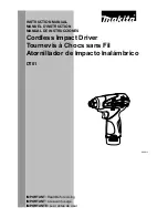
Cordless Impact Driver
*
1
Model number for North and Central American countries
C
ONCEPT AND MAIN APPLICATIONS
S
pecification
S
tandard equipment
O
ptional accessories
Note:
The standard equipment for the tool shown above may vary by country.
Model BTD146 Cordless Impact Driver is an advanced version of Model BTD141,
featuring the same ergonomically designed handle and 4-pole motor as the existing model,
plus more compact design, enhanced dust and drip-proof performance and battery fuel gauge
*
2
.
This product is powered by 18V/1.3Ah Li-ion battery BL1815 and 18V/3.0Ah Li-ion battery
BL1830.
See the product variation list above.
*5
torque at 3 seconds after seating, when fastening M14 high tensile bolt
*2
This gauge is available for all countries except North and Central American countries
Battery
No load speed: min.-
1
=rpm
Impacts per min.: min.-
1
=ipm
Max. fastening torque
*
5
: N.m (kgf.cm/ in.lbs)
Charging time: min.
Capacities
Electric brake
LED job light
Weight according to
EPTA-Procedure 01/2003: kg (lbs)
Variable speed control by trigger
Capacity: Ah
Cell
Voltage: V
18V
0 - 2,300
0 - 3,200
160 (1,630/ 1,420)
Standard bolt
High tensile bolt
Machine screw
Driving shank
M5 - M14 (3/16 - 9/16")
M5 - M12 (3/16 - 1/2")
Coarse thread screw
22 - 125mm (7/8 - 4-7/8")
M4 - M8 (5/32 - 5/16")
Yes
Yes
Yes
Reverse switch
Yes
1.3
*
3
/ 1.5
*
4
(2.8
*
3
/ 3.3
*
4
)
1.3/ 3.0 (battery BL1815/ BL1830)
Li-ion
220
approx. 15/ 22 with DC18RC or DC18RA
6.35mm (1/4") Hex
This product is available in the following variations.
Phillips bits
Socket bits
Drill chucks
Bit piece
Drill bits
with 6.35mm Hex shank
Hole saws for Impact driver
Stopper for Impact driver
Hook set (Belt clip)
Tool hanger
Battery protectors
Li-ion Battery BL1830
Li-ion Battery BL1815
Fast charger DC18RA
(for North and Central American countries only)
Fast charger DC18RC
(for all countries except North and Central American countries)
Charger DC18SD
Charger DC24SC
Automotive charger DC18SE
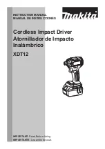
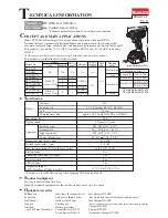
Dimensions: mm (")
Width (W)
Height (H)
Length (L) 138 (5-7/16)
79 (3-1/8)
238 (9-3/8)
*
4
220 (8-5/8)
*
3
*3
with Battery BL1815
*4
with Battery BL1830
W
L
H
(with Battery BL1830)
Max output (W)
T
ECHNICAL INFORMATION
BTD146RFE
BTD146Z
LXDT04Z
LXDT04ZW
BTD146RF
LXDT04
LXDT04CW
BTD146RFE3
BL1830
(Li-ion 3.0Ah)
BL1815
(Li-ion 1.3Ah)
No
DC18RC
DC18RC
DC18RA
DC18RA
No
Model No.
type
quantity
Charger
Yes
Belt
clip
1
2
No
Battery
cover
Yes
No
Plastic
carrying
case
2
0
1
BTD146RHE
1
2
3
2
No
Battery
Makita-blue
Makita-blue
White
White
Housing
color
1