

Continuous Rating (W)
Voltage (V)
Cycle (Hz)
Input
Output
Max. Output(W)
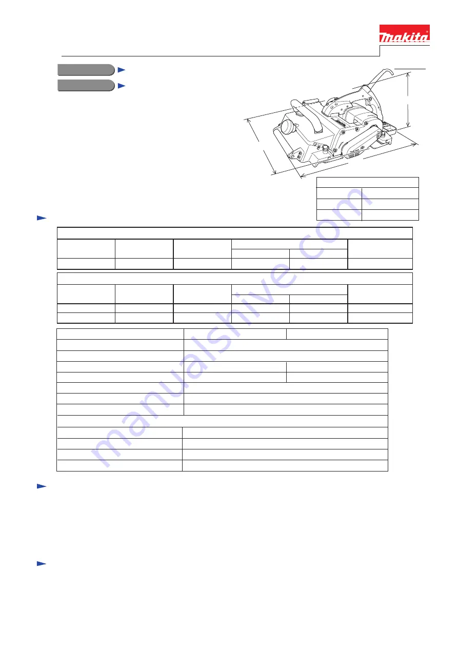
KP312, KP312S
Planers 312mm (12-9/32")
Models No.
Description
PRODUCT
Current (A)
T
ECHNICAL INFORMATION
C
ONCEPTION AND MAIN APPLICATIONS
S
pecification
S
tandard equipment
O
ptional accessories
< Note > The standard equipment for the tool shown may differ from country to country.
P 1 / 8
Dimensions : mm ( " )
Width ( W )
Height ( H )
Length ( L )
50 / 60
551 (21-3/4)
425 (16-3/4)
219 (8-5/8)
W
L
H
These new Power Planers have been developed as sister tools
to the existing Makita models KP301 or KP311, excelling
predecessors both in power and convenience.
Model KPS312S features soft start circuit
and overload protector.
120
15
1,700
690
2,450
KP312
Continuous Rating (W)
Voltage (V)
Cycle (Hz)
Input
Output
Max. Output(W)
220
Current (A)
50 / 60
50 / 60
230
10
11
2,200
2,200
1,040
820
3,000
3,850
KP312S
Model No.
Planing width : mm [in]
For Model KP312
* Socket wrench 9 ................ 1 pc.
* Triangular rule .................... 1 pc.
For Model KP312S
* Hex wrench ........................ 1 pc.
* Nozzle assembly ............... 1 pc.
* Triangular rule .................... 1 pc.
* Joint 70 .............................. 1 pc.
* Nozzle set
* Joint assembly
* Planer blade 312mm
Planing depth : mm [in]
Planer Blade (mm [in])
Soft Start
Overload Protector
No load speed (min
-1
= rpm)
Protection from Electric Shock
Net Weight :Kg (lbs )
Cord Length : m ( ft )
KP312
KP312S
12,000
312 [12-1/4]
No
Yes
No
Yes
Double Insulation
18 [39.7]
10 [32.8]
Capacity
0 - 150 [0 - 5-7/8]
150 - 240 [5-7/8 - 9-1/2]
240 - 312 [9-1/2 - 12-9/32]
3.5 [1/8]
2.0 [1/16]
1.5 [1/16]
<Note>
Supply of Model KP312 is restricted to low voltage
(110V - 120V) area.


