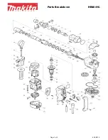
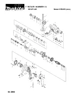
Model No.
Description
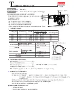
NEW TOOL
C
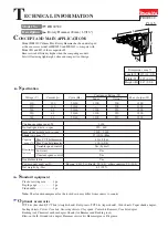
ONCEPT AND MAIN APPLICATIONS
P 1/ 2
3
S
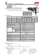
pecification
S
tandard equipment
O
ptional accessories
Side handle (D-shaped) .............. 1
Side handle (Bar-shaped) ........... 1
Depth gauge ............................... 1
TCT bits, Core bits, Bull points, Cold chisels, Scaling chisels,
Scaling chisel (for Tile), Grooving chisel, Clay spade, Bushing tool, Rammer,
Shank (for Bushing tool and Rammer), Chemical anchor adapter, Bit grease
Hammer grease, Side handle (D-shaped), Plastic carrying case, Blow-out bulb,
Safety goggle, Hammer service kit
Bit grease ................................. 1
Plastic carrying case ................ 1
Cleaning cloth .......................... 1
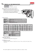
Dimensions: mm (")
Width (W)
Height (H)
Length (L)
Model No.
HR4501C
HR4510C
HR4511C
458 (18)
136 (5-3/8)
121 (4-3/4)
288 (11-3/8)
Note:
The standard equipment for the tool shown above may differ by country.
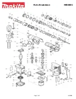
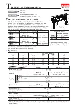
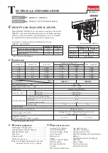
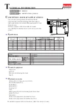
HR4501C, HR4510C, HR4511C
Rotary Hammers 45mm (1-3/4")
HR4501C series models have been developed as successor models
of HR4500C, featuring low vibration level and high work efficiency.
Listed below are their main features.
Active dynamic vibration absorber
Model No.
Vibration absorbing handle
Selectable two on-off switches
HR4501C
Yes
Yes
Yes
Yes
Yes
No
No
HR4510C HR4511C
No
No
HR4501C
L
H
W
HR4511C
HR4510C
No load speed: min-
1
=rpm
Impacts per min: min-
1
=ipm
Model No.
HR4501C
HR4510C
8.4 (18.5)
8.5 (18.7)
7.8 (17.2)
Europe: 4.0 (13.1), Other countries: 5.0 (16.4)
HR4511C
Shank type
Capacities: mm (")
Torque limiter
Double insulation
Net weight: kg (lbs)
Power supply cord: m (ft)
Electronic
features
Variable speed control by dial
Constant speed control
Soft start
Yes
Yes
Yes
Yes
Yes
45 (1-3/4)
125 (5)
130 - 280
1,250 - 2,750
Max Core bit diameter
Max TCT bit diameter
SDS-Max
T
ECHNICAL INFORMATION
120
110
220
230
240
14
1,350
---
600
1,600
50/60
7
1,350
600
1,700
50/60
7
1,350
600
1,700
50/60
7
1,350
600
1,700
50/60
13.5
600
1,600
50/60
Continuous Rating (W)
Voltage (V)
Cycle (Hz)
Input
Output
Max. Output (W)
Current (A)