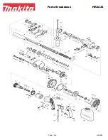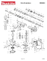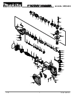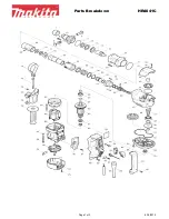


Model No.
Description
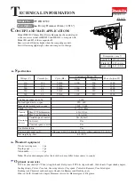
C
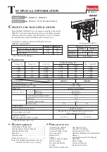
ONCEPT AND MAIN APPLICATIONS
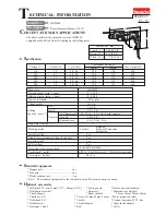
S
pecification
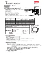
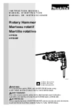
Dimensions: mm (")
Width (W)
Height (H)
Length (L)
479 (18-11/16)
HR4013C
112 (4-3/8)
HR4003C
106 (4-3/16)
263 (10-3/8)
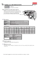
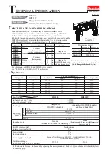
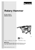
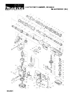
HR4013C, HR4003C
40mm (1-9/16") Rotary Hammer
Model HR4013C/HR4003C are the successor models of the current
HR4011C series models and developed to provide higher operating
efficiency and more comfort with unrivalled low level of vibration,
the optional dust extractor attachment newly designed, etc.
Listed below are the specification differences between
HR4013C and HR4003C.
S
tandard equipment
Note:
The standard equipment for the tool
shown above may vary by country.
Depth gauge (Stopper pole) ..........................1
Side handle assembly (D-shaped) .................1
Side handle (Bar style) ..................................1
Bit grease ......................................................1
Cleaning cloth ...............................................1
Plastic carrying case ......................................1
O
ptional accessories
Assorted TCT drill bits
Assorted Core bits
Assorted Bull points
Assorted Cold chisels
Assorted Scaling chisels
Scaling chisel (for Tile)
Grooving chisel
Shank (for Bushing tool and Rammer)
Bushing tool
Rammer
Scoop
Side handle assembly (D-shaped)
Chemical anchor adaptor
Bit Grease
Hammer grease
Safety Goggle
Bar style side handle
Plastic carrying case
Syringe
Hammer Service Kit
Dust extractor attachment
W
H
L
*Anti-Vibration Technology
AVT*
Active dynamic vibration absorber
Vibration absorbing housing
Soft no load
HR4013C HR4003C
Yes
Yes
Yes
No
No
No
PRODUCT
P 1/
19
T
ECHNICAL INFORMATION
(The image above is HR4013C.)
Adapted for SDS-MAX
Shank type
250 - 500
No load speed: min.
ˉ
¹ = rpm
1,450 - 2,900
Impacts per minute: min.
ˉ
¹ = ipm
Weight according to
EPTA-Procedure 01/2003
*
: kg (lbs)
Europe: 4.0 (13.1), Brazil, Chile, Peru: 2.0 (6.6),
Other countries: 5.0 (16.4)
Power supply cord: m (ft)
Double insulation
6.2 (13.8)
6.8 (15.1)
Protection from electric shock
Yes
Soft start
Yes
Constant speed control
No
Yes
Soft no load
Yes
Torque limiter
Capacity: mm (")
Electronic features
Concrete
105 (4-1/8)
40 (1-9/16)
Yes
Variable speed control switch
Core bit
TCT bit
HR4013C
HR4003C
Specification
Model
*
With Side handle (Bar style)
240
6.2
50/60
1,100
1,500
Continuous Rating (W)
Voltage (V)
Cycle (Hz)
Input
Output
500
Max. Output (W)
110
120
220
230
12
11
6.2
6.2
50/60
50/60
50/60
50/60
1,100
1,100
1,100
1,500
1,500
1,200
1,200
Current (A)
500
---
550
550
550