
HM1202, HM1202C
Demolition Hammers
Continuous Rating (W)
Voltage (V)
Current (A)
Cycle (Hz) Input
Output
Max. Output(W)
100
15.0
110
120
220
7.3
230
7.0
240
6.7
550
1800
Bit-type
SDS-Max
HM1202C
950-1900 (bpm)
Blows per minute
HM1202
1900 (bpm)
Net Weight
9.3kg (20.5 lbs)
Cord Length
5m (16.4 ft)
Bit Grease
Bull-Point 280
The standard equipment for the tools shown may differ form country to country.
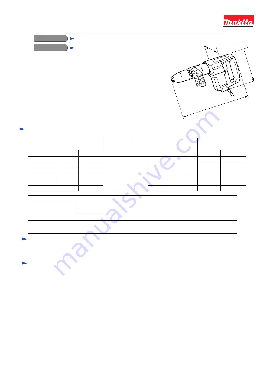
CONCEPTION AND MAIN APPLICATIONS
Specifications
Models No.
Product
T
ECHNICAL INFORMATION
Description
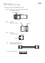
Standard equipment
Optional accessories
These demolition hammers are newly developped
as a 10 Kg hammer. (middel class between
HM1201 and HM1303 series models.)
Considerable strong demolishing power in this class,
However, softened reaction.
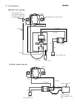
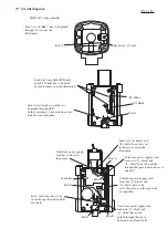
Model HM1202C : equipped with electronic control system
and variable speed control dial.
Model HM1202 : without the above features.
50/60
550
1800
550
1800
500
1600
500
1600
500
1600
HM1202 HM1202C
15.0
13.0
15.0
14.0
13.0
6.8
6.5
6.3
1,450
HM1202 HM1202C HM1202 HM1202C
750
750
750
700
700
700
1500
1500
1500
1600
1600
1600
Size of shank
18mm (11/16")
Bull Point 280
Bull Point 400
Cold Chisel 25x280
Cold Chisel 25x400
Scaling Chisel 50x400
Clay Spade 105x400
Hammer Grease
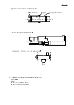
112mm(4-3/8")
258mm(10-1/8")
578mm(22-3/4")
P 1 / 14


