background image

US

GB

GB

GB

GB

GB

GB

GB

GB

GB

GB

GB

GB

GB

GB

GB

NOTICE

FEDERAL EMISSION COMPONENT DEFECT WARRANTY and CALIFORNIA
EMISSION CONTROL WARRANTY are applicable to only those engines/
generators complied with EPA (Environmental Protection Agency) and CARB
(California Air Resources Board) emission regulations in the U.S.A.
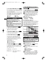
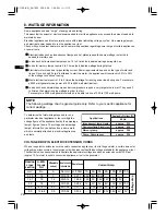
AIR INDEX

To show compliance with California emission regulations, a hangtag has been
provided displaying the Air Index level and durability period of this engine.

The Air Index level defines how clean an engine’s exhaust is over a period of
time. A bar graph scaled from “0” (most clean) to “10” (least clean) is used to
show an engine’s Air Index level. A lower Air Index level represents cleaner
exhaust from an engine.

The period of time (in hours) that the Air Index level is measured is known as
the durability period. Depending on the size of the engine, a selection of time
periods can be used to measure the Air Index level (see below).

Descriptive Term

Applicable to Emissions Durability Period

Moderate 

50 hours  (engine from 0 to 65 cc)

125 hours (engine greater than 65 cc)

Intermediate

-

125 hours (engine from 0 to 65 cc)
250 hours  (engine greater than 65 cc)

Extended

-

300 hours (engine from 0 to 65 cc)
500 hours  (engine greater than 65 cc)

Notice : This hangtag must remain on this engine or piece of equipment, and
only be removed by the ultimate purchaser before operation.

The engine exhaust from this product contains
chemicals known to the State of California to
cause cancer, birth defects or other reproductive
harm.

WARNING :

NOTICE

To the engines/generators exported to and used in the countries other than the
U.S.A., warranty service shall be performed by the distributor in each country in
accordance with the standard Makita engine/generator warranty policy as applicable.

G1100(US)_GU1835  2004.2.6  1:04 PM  ページ01

Summary of Contents for G1100

Page 1: ...urability period Depending on the size of the engine a selection of time periods can be used to measure the Air Index level see below Descriptive Term Applicable to Emissions Durability Period Moderate 50 hours engine from 0 to 65 cc 125 hours engine greater than 65 cc Intermediate 125 hours engine from 0 to 65 cc 250 hours engine greater than 65 cc Extended 300 hours engine from 0 to 65 cc 500 ho...

Page 2: ... Service Center or Service Center authorized by MAKITA during a warranty repair alteration accident failure to use the recommended fuel and oil or not performing required maintenance services The replacement parts used for required maintenance services Consequential damages such as loss of time inconvenience loss of use of the engine or equipment etc Diagnosis and inspection charges that do not re...

Page 3: ...ompano Beach FL 33064 954 781 6333 GEORGIA 4680 River Green Parkway NW Duluth GA 30096 770 476 8911 ILLINOIS 1450 Feehanville Dr Mt Prospect IL 60056 6011 847 297 3100 MARYLAND 7397 Washington Boulevard Suite 104 Elkridge MD 21075 410 796 4401 MASSACHUSETTS 232 Providence Highway Westwood MA 02090 781 461 9754 MINNESOTA 6427 Penn Ave South Richfield MN 55423 612 869 5199 MISSOURI 9876 Watson Rd St...

Page 4: ...equent purchaser that the engine is free from defect in material and workmanship that can cause the failure of a warranted emission related part WHAT IS COVERED UNDER THIS WARRANTY Repair and or replacement of any warranted emission related part will be performed at no charge provided the work is performed at an authorized warranty station There will also be no charge for any diagnostic labor perf...

Page 5: ...eaner element Every 200 hours 4 Clean and adjust spark plug and electrodes Every 200 hours Note More frequent maintenance may be necessary under dusty dirty or severe conditions REPAIR AND REPLACEMENT OF EMISSION RELATED PARTS It is recommended that only engine replacement parts which have been authorized and approved by MAKITA should be used in the performance of any warranty maintenance or repai...

Page 6: ...G1100 US _GU1835 2004 2 6 1 04 PM ページ06 ...

Page 7: ...re parts always give us the MODEL PRODUCTION NUMBER PROD No and SERIAL NUMBER SER No of your Product Please fill in the following blanks after checking the production number on your product Location of label is different depending on the product model CONTENTS 1 SAFETY PRECAUTIONS 2 2 COMPONENTS 5 3 CONTROLS AND INDICATORS 5 4 PRE OPERATION CHECKS 6 5 OPERATING PROCEDURES 7 6 WATTAGE INFORMATION 1...

Page 8: ...case piston seizure may occur even if the oil is above the upper level WARNING Pay attention to the wiring or extension cords from the generator to the connected device If the wire is under the generator or in contact with a vibrating part it may break and possibly cause a fire generator burnout or electric shock hazard Replace damaged or worn cords immediately WARNING Do not operate the generator...

Page 9: ...ll bystanders at a safe distance from work areas WARNING If wet wipe and dry it well before starting Do not pour water directly over the generator nor wash it with water WARNING Be extremely careful that all necessary electrical grounding procedures are followed during each and every use Failure to do so can be fatal WARNING It is absolutely essential that you know the safe and proper use of the p...

Page 10: ...o not connect the generator to the commercial power lines Engine oil ON power and Engine Add oil Battery charging condition OFF power and Engine Alternating current Direct current Plus positive polarity Minus negative polarity OUT position of a bistable push control IN position of a bistable push control Protective earth ground Fuse Choke cold starting aid Engine start Electric start Engine stop D...

Page 11: ...tops automatically When the engine stops due to oil shortage it can not be started anymore even by pulling the start knob just the alarm lamp flickers In such a case replenish engine oil up to the mouth of the oil filling port Refer to page 6 for details about the oil replenishing procedure 5 DC TERMINALS See Fig 2 2 r r DC electric power for battery charge is available Red is positive terminal Bl...

Page 12: ...Ambient temperature Single grade Multigrade 5W 10W 20W 20 30 40 10W 30 10W 40 Do not refuel while smoking or near open flame or other such potential fire hazards Otherwise fire accident may occur WARNING 7 RECOIL STARTER See Fig 2 2 y y Pull this handle to start the generator q RECOIL STARTER HANDLE q FUEL TANK CAP w FUEL FILTER SCREEN e TANK CAP COVER 8 GROUND TERMINAL See Fig 2 2 u u Terminal fo...

Page 13: ... a dry well ventilated area Keep exhaust pipe clear of foreign objects Keep generator away from open flame No smoking Keep generator on a stable and level surface Do not block generator air vents with paper or other material WARNING 5 OPERATING PROCEDURES See Fig 4 4 1 STARTING THE GENERATOR a Make sure the appliance is disconnected b Turn engine switch to CHOKE position When engine is warm or tem...

Page 14: ... output lamp is turned off during the proper operation 1 AC APPLICATION See Fig 4 4 r r a Make sure the output lamp is turned on b Turn off the switch es of the electrical appliance s before connecting to the generator c Insert the plug s of the electrical appliance s into the receptacle See Fig 4 r Check the amperage of the receptacles used referring to TABLE 1 and be sure not to take a current e...

Page 15: ...fluid can burn eyes and clothing Be extremely careful to avoid contact If injured wash the affected area immediately with large quantities of water and consult a doctor for treatment When charging a large capacity battery or totally discharged battery excessive current may force the DC breaker to turn off In such cases use a battery charger to charge a large battery with AC output Battery defects ...

Page 16: ...with questions regarding power surge of certain appliances or power tools 6 WATTAGE INFORMATION To determine the total wattage required to run a particular electrical appliance or tool multiply the voltage figure of the appliance tool by the amperage amps figure of same The voltage and amperage amps information can be found on a name plate which is normally attached to electrical appliances and to...

Page 17: ...rester will be very hot Allow the muffler to cool before cleaning the spark arrester How to remove the spark arrester 1 Remove the flange bolts from the muffler cover and remove the muffler cover 2 Remove the special screw from the spark arrester and remove the spark arrester from the muffler SPARK ARRESTER SCREEN SCREW MUFFLER Clean the spark arrester screen Use a brush to remove carbon deposits ...

Page 18: ...SSARY FOR THE USER OF THIS GENERATOR TO CONDUCT THE MAINTENANCE AND ADJUSTMENTS ON THE EMISSION RELATED PARTS LISTED BELOW TO KEEP THE EMISSION CONTROL SYSTEM EFFECTIVE The emission control system consists of the following parts The maintenance schedule indicated in the table is based on the normal generator operation Should the generator be operated in extremely dusty condition or in heavier load...

Page 19: ...ACLES Daily CLEAN AND ADJUST SPARK PLUG AND ELECTRODES REPLACE SPARK PLUG ENGINE SWITCH Daily DC TERMIANL Daily ROTOR STATOR REPLACE ENGINE MOUNT Note 1 Initial oil change should be performed after first twenty 20 hours of operation Thereafter change oil every hundred 100 hours Before changing oil check for a suitable way to dispose of old oil Do not pour it down into sewage drains onto garden soi...

Page 20: ...he drain screw of the carburetor See Fig 6 w q DRAIN SCREW Change engine oil Check for loose bolts and screws tighten them if necessary Clean generator thoroughly with oiled cloth Spray with preservative if available NEVER USE WATER TO CLEAN GENERATOR Pull starter handle until resistance is felt leaving handle in that position Store generator in a well ventilated low humidity area 1 ENGINE OIL CHA...

Page 21: ...r switch on the connected appliance and unplug Remove spark plug and clean electrode If the engine oil level is low add the oil to the upper level line on the oil gauge If loose push spark plug cap back into place When No Electricity Is Generated at Receptacle When Engine Fails to Start Check if the breaker is not activated with the overload lamp turned on Check if the DC circuit breaker is turned...

Page 22: ...5 8 Fuel Automotive Unleaded Gasoline Fuel tank capacity L US gal 3 5 0 93 Rated continuous operation Approx hours 3 7 Starting system Recoil starter Dimension Length mm in 490 19 3 Width mm in 295 11 6 High mm in 445 17 5 Dry weight kg lb 25 55 1 US GB GB GB GB GB GB GB GB GB GB GB GB GB GB GB Valve Clearance Intake Exhaust mm in 0 1 0 03 0 0039 0 0012 Note Adjust the valve clearance while the en...

Page 23: ... White Org Orange Gry Gray R Red W White Y Yellow Grn Y Green Yellow W Blk White Black Pur Purple GENERATOR CONTROL PANEL DC coil ACreceptacle 230V NEON LAMP OIL LED Grn Y W R Org Brn W R W Earth ground terminal Main coil 1 Main coil 2 ENGINE AVR Field Winding Brush Brush Exciter coil Ignition coil Stop switch Spark plug Oil sensor control unit Oil sensor Grn Y Blk G1100 US _GU1835 2004 2 6 1 04 P...

Page 24: ...G1100 US _GU1835 2004 2 6 1 04 PM ページ18 ...

Reviews: