


Model No.
Description
C
ONCEPT AND MAIN APPLICATIONS
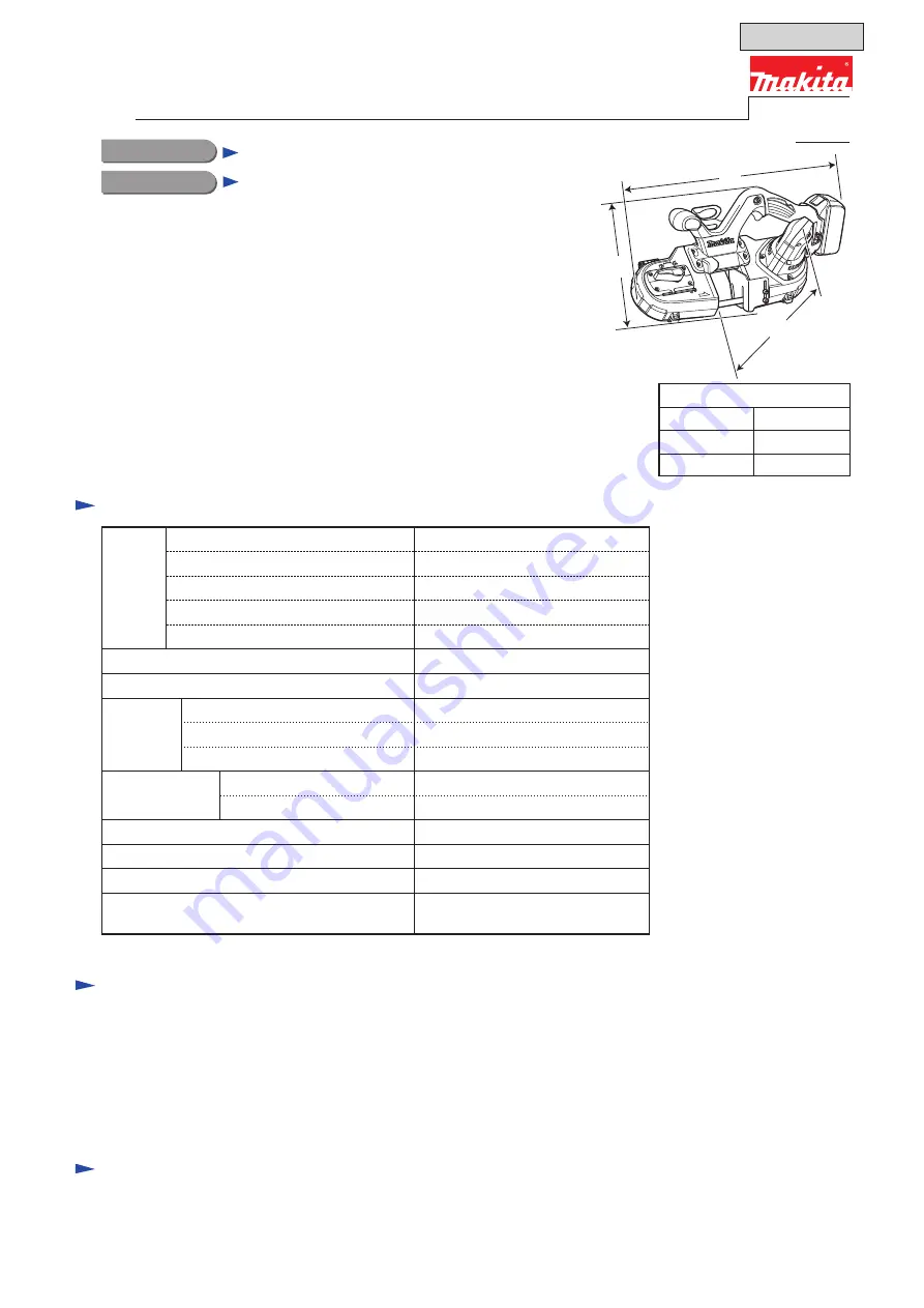
Dimensions
*
1
: mm (")
Width (W)
Height (H)
Length (L)
468 (18-1/2)
197 (7-3/4)
233 (9-1/8)
*
1
With Battery BL1830, BL1840
or BL1850
OFFICIAL USE
for ASC & Sales Shop
DPB181
Cordless Portable Band Saw
Model DPB181 is lightweight and compact cordless portable band saw.
The design is specialized in excellent maneuverability in horizontal and
overhead applications.
The following features are the same as BPB180/ DPB180.
• Adjustable stopper plate
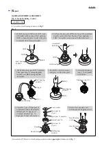
• Easy blade replacement
• powered by 18V Makita Li-ion battery
Battery protection circuit is equipped with DPB181. The function works when
the battery with a star mark is set on DPB181.
Note
: BL1815 is not compatible.
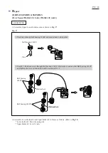
Battery
*4
Charger
*4
Battery cover
*5
Band saw blade 13-835 (18 teeth per inch)
Hex wrench 4
Wheel cover set (for some countries)
Tool bag (for some countries)
Fast charger DC18RC
Charger DC18SD
Charger DC24SC
Automotive charger DC18SE
Battery BL1815N
Battery BL1820
Battery BL1830
Battery BL1840
Battery BL1850
Battery
Variable speed control dial
Blade speed: m/s (ft/min.)
Type
Voltage: V
Capacity: Ah
Li-ion
18
1.5, 2.0, 3.0, 4.0, 5.0
No
Weight according to
EPTA-Procedure 01/2003
*
2
: kg (lbs)
3.2 (7.1)
*
3
3.5 (7.7)
*
1
Overload protector
No
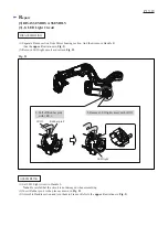
LED job light
Yes
3.2 (630)
Max output (W)
350
Square pipe [width x height]
Length
Width
Height
Cutting capacity:
mm (")
Blade size:
mm (")
Round pipe [diameter]
64 x 64 (2-1/2 x 2-1/2)
13 (1/2)
0.5 (0.02)
835 (32-7/8)
64 (2-1/2)
Note:
The standard equipment may vary by country or model variation.
PRODUCT
P 1/ 18
*
2
With Band saw blade 13-835 and Battery
*
3
With Battery BL1815N or BL1820
*4
Battery and Charger are not supplied with “Z” model.
*5
Supplied with the same quantity of extra Battery
S
pecification
S
tandard equipment
O
ptional accessories
Band saw blade 13-835
(14, 18, 24 teeth per inch)
Wheel cover set
Hook set
Cutting wax
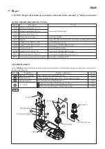
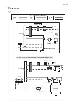
T
ECHNICAL INFORMATION
Energy capacity: Wh
27, 36, 54, 72, 90
Charging time (approx.): min.
15, 24, 22, 36, 45 with DC18RC
L
W
H


