

The subject models are cordless angle grinders powered by 18V Li-ion battery,
and equipped with highly enhanced Brushless DC motor compared to the current
models DGA402/ DGA452.
・
A built-in controller changes the cutting speed automatically according to
load condition, enabling the user to obtain high speed rotation on light duty
application/ high torque on heavy duty application.
・
KBD:
K
ick-
B
ack
D
etection shuts down the tool to protect the user,
if the rotation speed suddenly slows down (e.g., kickback).
・
Paddle switch type
Model No.
Description
PRODUCT
T
ECHNICAL INFORMATION
C
ONCEPT AND MAIN APPLICATIONS
S
pecification
S
tandard equipment
O
ptional accessories
P 1/ 11
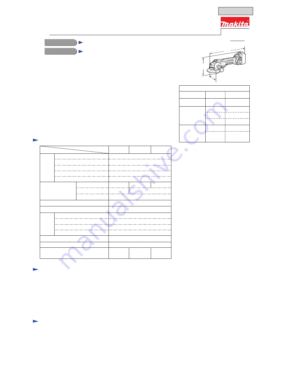
Dimensions: mm (")
DGA405
Width (W)
DGA455
117 (4-5/8)
130 (5-1/8)
DGA505
DGA405
Height (H)
140 (5-1/2)
140 (5-1/2)
DGA455,
DGA505
145 (5-3/4)
Note:
The standard equipment may vary by country or model variation.
DGA405, DGA455, DGA505
18V Cordless Angle Grinders
L
H
W
Specification
Model DGA405
18
Weight according to
EPTA-Procedure 01/2003: kg(lbs)*
2
2.5 (5.6) 2.6 (5.7)
2.4 (5.4)
Battery
1.5, 2.0, 3.0, 4.0, 5.0
Capacity: Ah
Voltage: V
Li-ion
Cell
Energy capacity: Wh
27, 36, 54, 72, 90
Charging time (approx.): min. 15, 24, 22, 36, 45 with DC18RC
Wheel size: mm (") Hole diameter
6 (1/4)
Max. thickness
Diameter
100 (4)
16 (5/8)
22.23 (7/8)
8,500
No
Yes
Yes
Yes
Yes
Yes
Paddle
Switch type
Electronic control
Overload warning lamp
Electronic current limiter
Soft start
Anti-restart function
Battery fuel gauge
Soft grip
*2
With BL1830/ BL1840/ BL1850
*1
With BL1830/ BL1840/ BL1850
*2
With BL1815N/ BL1820
Note
: BL1815 is not compatible.
DGA505
DGA455
115 (4-1/2) 125 (5)
Lock nut wrench
Side grip
Depressed center wheel (100mm for DGA405, 115mm for DGA455, 125mm for DGA505)
Battery cover (except “Z” model)
Plastic carrying case (except “Z” model)
Fast charger DC18RC (except “Z” model)
Li-ion battery BL1830 or BL1840 (except “Z” model)
Wheel covers
Vibration proof grip
Wire cup brush
Dust extractor attachment
Super flange
Dust collecting wheelcover
Lock nut
Dust collect cover
Sanding lock nut
Rubber pads
Abrasive discs
Fast charger DC18RC
Fast charger DC18SD
Charger DC24SC
Automotive charger DC18SE
Four port multi charger DC18SF
Dust collecting wheel guards
Li-ion battery BL1815N
Li-ion battery BL1820
Li-ion battery BL1830
Li-ion battery BL1840
Li-ion battery BL1850
Length (L)
*
1
All
362 (14-1/4)
Length (L)
*
2
All
348 (13-3/4)
OFFICIAL USE
for ASC & Sales Shop
No load speed: min.-ı= rpm