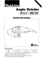
Makita 9049, Instruction Manual
The Makita 9049 is a powerful and reliable tool that can tackle any task with ease. To ensure you get the most out of this product, it is important to have the Instruction Manual handy. You can conveniently download the manual for free from manualshive.com, providing you with valuable information on operating and maintaining your Makita 9049.
Share
Download


Reviews:
No comments
Related manuals for 9049
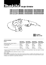
9047
Brand: Makita Pages: 8
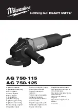
AG 750-115
Brand: Milwaukee Pages: 51
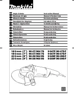
9047
Brand: Makita Pages: 52
NAG115
Brand: NUTOOL Pages: 112
AG4531G
Brand: Ryobi Pages: 36
SX232B
Brand: Sunex Pages: 13
GA7060
Brand: Makita Pages: 108
GWS 9-125 Professional
Brand: Bosch Pages: 295
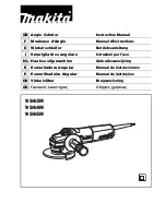
9553HN
Brand: Makita Pages: 68

9553NB
Brand: Makita Pages: 2
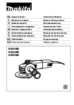
9553NB
Brand: Makita Pages: 60
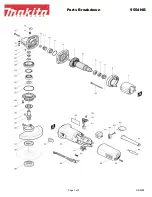
9554NB
Brand: Makita Pages: 3
9564CVL
Brand: Makita Pages: 76
GA4030
Brand: Makita Pages: 72
GA7050
Brand: Makita Pages: 104
GA7061
Brand: Makita Pages: 100

XAG01
Brand: Makita Pages: 11

GWS 12-125 CI Professional
Brand: Bosch Pages: 430


