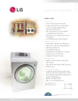
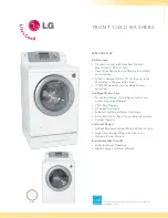
background image

100

WASHING MACHINE

SERVICE MANUAL      

READ THIS MANUAL CAREFULLY TO DIAGNOSE 
PROBLEMS CORRECTLY BEFORE SERVICING THE UNIT.

MODEL : WM2411HW / WM2011 HS

WM2011HW / WM1811CW
WM2432HW / WM2032 HS
WM2032HW / WM1832CW

CAUTION    

Website:http://www.LGEservice.com
E-mail:http://www.LGEservice.com/techsup.html

Summary of Contents for WD-10210BD

Page 1: ...THIS MANUAL CAREFULLY TO DIAGNOSE PROBLEMS CORRECTLY BEFORE SERVICING THE UNIT MODEL WM2411HW WM2011 HS WM2011HW WM1811CW WM2432HW WM2032 HS WM2032HW WM1832CW CAUTION Website http www LGEservice com E mail http www LGEservice com techsup html ...

Page 2: ...RE PERFORMING SERVICE 15 7 2 QC TEST MODE 15 7 3 HOW TO CHECK THE WATER LEVEL FREQUENCY 15 7 4 ERROR DISPLAY 16 8 ERROR DIAGNOSIS AND CHECK LIST 18 8 1 DIAGNOSIS AND SOLUTION FOR ABNORMAL OPERATION 18 8 2 FAULT DIAGNOSIS AND TROUBLESHOOTING 21 9 DISASSEMBLY INSTRUCTIONS 28 10 EXPLODED VIEW 36 10 1 CABINET CONTROL PANEL ASSEMBLY 36 10 2 DRUM TUB ASSEMBLY 37 10 3 DISPENSER ASSEMBLY 38 ...

Page 3: ... Cycle Extra Rinse Rinse Spin Delay Wash CUSTOM PROGRAM Incorporated WATER CIRCULATION Incorporated OPERATIONAL WATER PRESSURE 4 5 145 psi 30 1000 kPa CONTROL TYPE Electronic WASH CAPACITY 3 22 cu ft 3 72 cu ft IEC DIMENSIONS 27 W X 29 1 2 D X 42 3 4 H 49 4 5 D door open DELAY WASH up to 19 hours up to 12 hours up to 9 hours DOOR SWITCH TYPE PTC Solenoid WATER LEVEL 7 steps by sensor LAUNDRY LOAD ...

Page 4: ... Detergent suds are eliminated more easily by the water shower during rinse cycle The water circulation system uses both water and detergent more efficiently RollerJets WM2411HW WM2011HS WM2011HW WM2432HW WM2032HS WM2032HW The washing ball enhances wash performance and reduces damage to clothing The jets spray and help tumble clothes to enhance washing performance while maintaining fabric care Bui...

Page 5: ...ram then proceeds Spinning does not proceed until the water in the tub drains to a certain level 2 4 DOOR CONTROL The door can be opened by pulling the door handle whenever washer is not in operation When the cycle is completed the DOOR LOCKED light will turn off If a power failure has occurred while in operation the door will lock for 5 minutes Clicking sounds can be heard when the door is locked...

Page 6: ...6 3 PARTS IDENTIFICATION ACCESSORIES If the supply cord is damaged it must be replaced by the manufacturer or its authorized service technician in order to avoid a hazard ...

Page 7: ...ns correctly STANDARD INSTALLATION The appliance should be installed as follows REMOVE THE TRANSIT INSTALL THE APPLIANCE ADJUST THE BOLTS ON A FLAT AND FIRM SURFACE LEVELING Remove the transit bolts Turn the leveling feet to adjust 4 EA with the supplied wrench the appliance horizontally Keep the transit bolts and spanner for future use Insert the 4 caps provided into the hole The appliance goes u...

Page 8: ...mly to prevent leaks CONNECT THE DRAIN HOSE CONNECT POWER PLUG The end of the drain hose should be placed less than 96 from the floor Connect the power plug to the wall outlet Avoid connecting several electric devices as doing so may cause a fire Make sure that the hose is not twisted Avoid submerging the end of the hose ...

Page 9: ...C is required remove the remaining water in the tub by pulling out the drain plug Preparation for Press the POWER button Press the Start Pause washing button Press the WASH RINSE button Make sure that the drum rotates Verify that if water is supplied and the present temperature will clockwise and counterclockwise through the detergent dispenser be displayed Check the water heating Check the automa...

Page 10: ...Press and hold the Custom Program button for 3 seconds 2 beep sounds 5 Press the Start Pause button The Custom Program is now stored for future use To reuse the program select Custom Program and press Start Pause Lights whenever the door is locked The door can be unlocked by pressing the Start Pause button to stop the washer Choose High Low Select a water temperature based on load you are washing ...

Page 11: ...he wash and rinse cycles for better stain removal Automatically provides a rinse Quick Cycle The Quick cycle offers a quick cycle time Extra Rinse This option provides an additional rinse cycle Rinse Spin Use this option to rinse and then spin Delay Wash Allows the start of any cycle to be delayed for 1 19 12 9 hours Use this button to Start Stop the washer w Off on the type of he ed setting is e ...

Page 12: ...12 WM2411HW WM2011HS WM2011HW WM1811CW WM2432HW WM2032HS WM2032HW WM1832CW ...

Page 13: ...13 6 WIRING DIAGRAM PROGRAM CHART WM2411HW WM2011HS WM2011HW WM2432HW WM2032HS WM2032HW WM1811CW WM1832CW ...

Page 14: ...14 ...

Page 15: ...ter level frequency x 1 kHz Check Point Display Status None Turns on all lamps and locks the door 1 time Tumble clockwise rpm 40 50 2 times Low speed Spin rpm 3 times High speed Spin rpm 4 times Inlet valve for prewash turns on Water level frequency 25 65 5 times Inlet valve for main wash turns on Water level frequency 25 65 6 times Inlet valve for hot water turns on Water level frequency 25 65 7 ...

Page 16: ...d within 8 minutes after water is supplied or it does not reach the preset water level within 25 minutes The load is too small The appliance is tilted Laundry is gathered to one side Non distributable things are put into the drum 1 2 IMBALANCE ERROR Not fully drained within 10 minutes 3 DRAIN ERROR Water is overflowing over 8 level If is displayed the drain pump will operate to the drain water aut...

Page 17: ...e white connector in the MAIN PWB ASSEMBLY is bad or unstable The MOTOR HARNESS between the STATOR ASSEMBLY and MAIN PWB ASSEMBLY is cut open circuited The hall sensor is out of order defective 8 9 LOCKED MOTOR ERROR Loose Ball Sensor Connector Ball Sensor is out of order Displayed only when the START PAUSE button is first pressed in the QC Test Mode 10 BALL SENSOR ERROR The washer experienced a p...

Page 18: ...S YES YES NO NO YES NO NO Is the power plug connected firmly to 120V AC outlet Power failure or Breaker opened Is the outlet controlled by a switch Visit to service Is displayed Is the tap opened Is the tap frozen Is the water supply shut off Is filter in the inlet valve clogged with foreign material Visit to service Clean the filter of inlet valve ...

Page 19: ...19 SYMPTOM GUIDE FOR SERVICE CALL Door error Drain trouble Was the load too large Visit to service Visit to service ...

Page 20: ...ed as recommended Recommend to reduce the amount of detergent Is softener put in the correct compartment of the dispenser Is the softener cap clogged Explain proper use of softener Clean the softener compartment Visit to service LOW SUDSING This appliance has an automatic suds sensing function which prevents overflow When excessive suds are sensed the suds removing implementations such as drain wa...

Page 21: ...SEMBLY or repair wire Check the fuse or reset the circuit breaker Replace the FILTER ASSEMBLY CIRC Replace MAIN PWB ASSEMBLY Reconnect Replace the MAIN PWB ASSEMBLY NO POWER 21 8 2 FAULT DIAGNOSIS AND TROUBLESHOOTING 1 Be careful of electric shock if disconnecting parts while troubleshooting 2 First of all check the connection of each electrical terminal with the wiring diagram 3 If you replace th...

Page 22: ...lve connector is 120V AC Refer to 7 2 QC TEST MODE Is water supplied Are receptacles correctly connected to the terminals of the INLET VALVE ASSEMBLY Has detergent been put in the correct compartment of the dispenser Is the detergent caked or hardened Open the tap Check the AIR CHAMBER and the tube clogged Clean the filter Replace the INLET VALVE ASSEMBLY Check electrical connection Replace the MA...

Page 23: ...ring on the dispenser Put it in the correct compartment Clean the Cap and Container Is the motor bolt loosened Is there friction noise coming from the motor Is water supplied Are the plugs correctly connected to the terminals of the INLET VALVE ASSEMBLY Is softener bleach put in the correct compartment of the drawer Is the softener bleach cap clogged ...

Page 24: ...requency 255 When pressing SPIN SPEED and SOIL LEVEL buttons at the same time while wash is the water level frequency between 230 243 Check the voltage between two pins while pressing the POWER button Is the voltage 120V AC Is the drain hose twisted or frozen Is the impeller of the drain pump clogged Is the connector disconnected disassembled Is the coil of the drain pump too high or low resistanc...

Page 25: ...25 Push the THERMISTOR tightly to the rubber When checking the THERMISTOR on the tub is the THERMISTOR loose HEATING CONTINUOUSLY ABOVE THE SETTING WATER TEMPERATURE WASH HEATER TROUBLE ...

Page 26: ... Hose clogged Is the connector disconnected disassembled Is the coil of the right side of drain pump open or short circuited Coil R is 18 30Ω When checking voltage between the connectors during spin is the voltage 120V AC as the figure Remove foreign material Remove foreign material Reconnect or repair the connector Replace PUMP MOTOR ASSEMBLY Replace the MAIN PWB ASSEMBLY 26 ...

Page 27: ...g at low speed Is it disconnected or disassembled Red 3pin 1 NA 4pin 2 Check the motor connector Is the resistance of the terminal the same as the figure MOTOR TERMINAL Resistance of terminal L M M N N L About 5Ω 15Ω Replace the MAIN PWB ASSEMBLY Does the spring of Latch Hook actuate Is there clicking sound once or twice when the START PAUSE button is pressed to start the cycle Is DOOR SWITCH ASSE...

Page 28: ...ler assembly 1 Open the Lid 2 Unscrew 4 screws 3 Disassemble the Lid Assembly 4 Pull down the Dispenser by pushing hooks 5 Put a hand into the dispenser hole and hold the top plate 6 Push backward using an opener and lift the top plate 9 DISASSEMBLY INSTRUCTIONS ƒR Disassemble and repair the unit only after pulling out power plug from the outlet LID Do first left side L ...

Page 29: ...es 3 Unscrew the nut at the lower part of the dispenser 4 Unscrew the 4 screws on the holder 5 Disassemble the 5 connectors from the valves 1 Unscrew the screw from the top plate 2 Unplug the 2 connectors Wire color L WH BK M OR BK N WH BK O GY BK P BL BK ...

Page 30: ...ews from upper side of the cabinet cover 2 Unscrew the screw from filter cover 3 Put a flat screwdriver into the both sides of the filter cover and pull it out 4 Unscrew the 2 screws from the lower side of the cabinet cover ...

Page 31: ...bly using a flat screwdriver 7 Separate the clamp assembly from cabinet cover 8 Tilt the cabinet cover 9 Disconnect the door switch connector 10 Lift and separate the cabinet cover 11 Disassemble the clamp assembly using a flat screwdriver 12 Disasemble the Gasket ...

Page 32: ...a flat screwdriver into the opening of the hinge and pull out the hinge cover 4 Unscrew the screws from the door 5 Disassemble the door upward downward 1 Open the door 2 Disassemble the clamp assembly 3 Unscrew the 2 screws from cabinet cover Be careful The door is heavy ...

Page 33: ...isassemble the cabinet cover 2 Separate 2 connectors from the heater 3 Loose the nut and pull out the heater 1 Disassemble the cabinet cover 2 Unplug the white connector from the thermistor 3 Pull it out by holding the bracket of thermistor CAUTION When assembling the heater insert the heater into heater clip on the bottom of the tub Tighten the fastening nut so the heater is secure ...

Page 34: ...ater from the tub 3 Remove any foreign objects wire coin etc by inserting a long bar in the opening 1 Unscrew the 4 screws from the back cover 2 Unscrew the single screw from the lower right side of the cabinet 3 Disconnect the connector from PWB Harness ...

Page 35: ... Loosen the bolt 3 Pull out the Rotor 4 Unscrew the 2 screws from the tub bracket 5 Loosen the 6 bolts on the stator 6 Unplug the 2 connectors from the stator 1 Disassemble the damper hinges from the tub and base 2 Separate the dampers ...

Page 36: ...36 10 1 CABINET CONTROL PANEL ASSEMBLY 10 EXPLODED VIEW A160 A125 A105 F215 A495 A490 A303 ...

Page 37: ...37 K344 K345 K123 K115 K111 K340 F315 F463 K125 K343 K121 K101 K122 F141 K105 F463 F464 10 2 DRUM TUB ASSEMBLY ...

Page 38: ...38 F300 F160 F170 F120 A275 HOT BLUE A276 COLD RED F430 F435 F431 F440 F436 F432 F302 F301 10 3 DISPENSER ASSEMBLY ...

Page 39: ... HOSE INLET 5215FD3715H 1 A303 CAP COVER 5006FR3146A 1 A410 SWITCH ASSEMBLY SENSOR SWITCH 6600FA1704X 1 A430 POWER CORD ASSEMBLY 6411ER1004S 1 A440 SWITCH ASSEMBLY DOOR 6601ER1004B 1 A485 FILTER ASSEMBLY CIRC 6201EC1004L 1 A490 BRACKET ASSEMBLY 4811ER3001A 1 A495 SENSOR ASSEMBLY 6501FA2462C 1 F120 HARNESS PWB 6877ER1015B 1 F140 HARNESS MOTOR 6877ER1016B 1 F141 HARNESS MOTOR 6877ER3003B 1 F160 VALV...

Page 40: ...OR ASSEMBLY 6322FR2046C 1 K320 HEATER ASSEMBLY 5301FR1158J 1 K340 MOTOR ASSEMBLY PUMP 4681EA2001D 1 K343 CLAMP 4860FR3092C 2 K344 CASING PUMP 3108ER1001A 1 K345 MOTOR ASSEMBLY PUMP 4681EA2001C 1 K350 STATOR ASSEMBLY 4417FA1994G 1 K360 ROTOR ASSEMBLY 4413EA1002B 1 K410 SPRING HINGE 4970FR2084D 2 K411 HOLDER 4930FR3040A 2 K510 GASKET 4986ER0001A 1 K520 BELLOWS 4738ER1002A 1 K530 CLAMP ASSEMBLY 4861E...

Page 41: ... HOSE INLET 5215FD3715H 1 A303 CAP COVER 5006FR3146A 1 A410 SWITCH ASSEMBLY SENSOR SWITCH 6600FA1704X 1 A430 POWER CORD ASSEMBLY 6411ER1004S 1 A440 SWITCH ASSEMBLY DOOR 6601ER1004B 1 A485 FILTER ASSEMBLY CIRC 6201EC1004L 1 A490 BRACKET ASSEMBLY 4811ER3001A 1 A495 SENSOR ASSEMBLY 6501FA2462C 1 F120 HARNESS PWB 6877ER1015B 1 F140 HARNESS MOTOR 6877ER1016B 1 F141 HARNESS MOTOR 6877ER3003B 1 F160 VALV...

Page 42: ...OR ASSEMBLY 6322FR2046C 1 K320 HEATER ASSEMBLY 5301FR1158J 1 K340 MOTOR ASSEMBLY PUMP 4681EA2001D 1 K343 CLAMP 4860FR3092C 2 K344 CASING PUMP 3108ER1001A 1 K345 MOTOR ASSEMBLY PUMP 4681EA2001C 1 K350 STATOR ASSEMBLY 4417FA1994G 1 K360 ROTOR ASSEMBLY 4413EA1002B 1 K410 SPRING HINGE 4970FR2084D 2 K411 HOLDER 4930FR3040A 2 K510 GASKET 4986ER0001A 1 K520 BELLOWS 4738ER1002A 1 K530 CLAMP ASSEMBLY 4861E...

Page 43: ...LET 5215FD3715H 1 A303 CAP COVER 5006FR3146A 1 A410 SWITCH ASSEMBLY SENSOR SWITCH 6600FA1704X 1 A430 POWER CORD ASSEMBLY 6411ER1004S 1 A440 SWITCH ASSEMBLY DOOR 6601ER1004B 1 A450 PWB PCB ASSEMBLY MAIN 6871EC1081B 1 A485 FILTER ASSEMBLY CIRC 6201EC1004L 1 A490 BRACKET ASSEMBLY 4811ER3001A 1 A495 SENSOR ASSEMBLY 6501FA2462C 1 F120 HARNESS PWB 6877ER1015B 1 F140 HARNESS MOTOR 6877ER1016B 1 F141 HARN...

Page 44: ...K310 THERMISTOR ASSEMBLY 6322FR2046C 1 K320 HEATER ASSEMBLY 5301FR1158J 1 K340 MOTOR ASSEMBLY PUMP 4681EA2001D 1 K343 CLAMP 4860FR3092C 2 K344 CASING PUMP 3108ER1001A 1 K345 MOTOR ASSEMBLY PUMP 4681EA2001C 1 K350 STATOR ASSEMBLY 4417FA1994G 1 K360 ROTOR ASSEMBLY 4413EA1002B 1 K410 SPRING HINGE 4970FR2084D 2 K411 HOLDER 4930FR3040A 2 K510 GASKET 4986ER0001A 1 K520 BELLOWS 4738ER1002A 1 K530 CLAMP A...

Page 45: ... HOSE INLET 5215FD3715H 1 A303 CAP COVER 5006FR3146A 1 A410 SWITCH ASSEMBLY SENSOR SWITCH 6600FA1704X 1 A430 POWER CORD ASSEMBLY 6411ER1004S 1 A440 SWITCH ASSEMBLY DOOR 6601ER1004B 1 A485 FILTER ASSEMBLY CIRC 6201EC1004L 1 A490 BRACKET ASSEMBLY 4811ER3001A 1 A495 SENSOR ASSEMBLY 6501FA2462C 1 F120 HARNESS PWB 6877ER1015C 1 F140 HARNESS MOTOR 6877ER1016B 1 F141 HARNESS MOTOR 6877ER3003C 1 F160 VALV...

Page 46: ...K141 SEAL 4036ER4001B 1 K310 THERMISTOR ASSEMBLY 6322FR2046C 1 K340 MOTOR ASSEMBLY PUMP 4681EA2001D 1 K343 CLAMP 4860FR3092C 2 K344 CASING PUMP 3108ER1001B 1 K350 STATOR ASSEMBLY 4417FA1994G 1 K360 ROTOR ASSEMBLY 4413EA1002B 1 K410 SPRING HINGE 4970FR2084D 2 K411 HOLDER 4930FR3040A 2 K510 GASKET 4986ER0001B 1 K520 BELLOWS 4738ER1002A 1 K530 CLAMP ASSEMBLY 4861ER2001D 1 K531 CLAMP 4861FR3068E 2 K54...

Page 47: ......

Page 48: ...101 DEC 2002 PRINTED IN KOREA P No 3828ER3013T ...

Reviews: