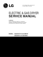
background image

U.S.A. Website: http://us.lgservice.com
Canadian Website: http://lg.ca

ELECTRIC & GAS DRYER

SERVICE MANUAL

CAUTION    

READ THIS MANUAL CAREFULLY IN ORDER TO
PROPERLY DIAGNOSE PROBLEMS AND TO SAFELY
PROVIDE QUALITY SERVICE ON THESE DRYERS.

MODEL : DLE5955W / DLG5966W

DLE5955G / DLG5966G

Summary of Contents for Tromm DLE5955G

Page 1: ...om Canadian Website http lg ca ELECTRIC GAS DRYER SERVICE MANUAL CAUTION READ THIS MANUAL CAREFULLY IN ORDER TO PROPERLY DIAGNOSE PROBLEMS AND TO SAFELY PROVIDE QUALITY SERVICE ON THESE DRYERS MODEL DLE5955W DLG5966W DLE5955G DLG5966G ...

Page 2: ...MAR 2007 PRINTED IN KOREA P No 3828EL3005L ...

Page 3: ...blems are present everywhere ESD may damage or weaken the electronic control assembly The new control assembly may appear to work well after repair is finished but failure may occur at a later date due to ESD stress Use an anti static wrist strap Connect wrist strap to green ground connection point or unpainted metal in the appliance OR Touch your finger repeatedly to a green ground connection poi...

Page 4: ...ST 22 9 3 TEST 3 MOTOR TEST 24 9 4 TEST 4 MOISTURE SENSOR 25 9 5 TEST 5 DOOR SWITCH TEST 26 9 6 TEST 6 HEATER SWITCH TEST ELECTRIC MODEL 27 9 7 TEST 7 GAS VALVE TEST GAS MODEL 28 9 8 TEST 8 SEMI CONDUCTOR 29 10 CHANGE GAS SETTING NATURAL GAS PROPANE GAS 30 11 DISASSEMBLY INSTRUCTIONS 32 12 EXPLODED VIEW 39 12 1 CONTROL PANEL PLATE ASSEMBLY 39 12 2 CABINET DOOR ASSEMBLY 40 12 3 1 DRUM MOTOR ASSEMBL...

Page 5: ... regarding detailed information Size 27 X 29 9 X 38 7 inch Dryer capacity IEC 7 3 cu ft Weight 126 Ibs Specifications are subject to change by manufacturer ACCESSORIES Dryer rack 1 each Stacking kit 1 each Purchased Separately Pedestal 1 each Purchased Separately See page 6 See page 7 See page 8 ...

Page 6: ...l Finish DLE5955G DLG5966G DLE5955W DLG5966W ITEM Child Lock Reversible Door Interior Light Product WxHxD Packing WxHxD Sound levels Dryer Rack Drum No of Dry Levels No of Dry Options No of Programs DRUM CAPACITY CONTROL TYPE No of Temperature Controls Weight lbs Net Gross AC 120V GASMODEL AC 240V ELECTRICMODEL Electrode sensor Thermistor AC 120V AC 120V REMARK Available Available Available Availa...

Page 7: ...LATION INSTRUCTIONS 3 Open the door Hold the dryer rack with both hands Put the dryer rack into the drum Check and be sure that the front of the rack is properly seated behind the lint filter 1 2 3 Dryer Rack Installation Instructions ...

Page 8: ...dryer on top of the washer by placing the legs as shown Be careful not to pinch fingers between the washer and dryer Slide the dryer back against the stop on the side rail Insert the front rail of the stacking kit Push the front rail back against the stops on the side brackets Do not use a stacking kit with a gas dryer in potentially unstable conditions like a mobile home Stacking kit Do not attem...

Page 9: ... be placed on a solid and level floor for proper operation Adjust the legs of the appliance and pedestal by turning with a wrench Then adjust the lock unt toward the pedestal while holding the pedestal leg using a wrench 1 Remove pedestal installation hardware and instructions from the shipping carton 2 Position the dryer on top of the pedestal 3 Remove the paper from the bracket for washer combo ...

Page 10: ... wires a hook shape Then put the hooked shape end of the wire under the screw of the terminal block hooked end facing rightward and pinch the hook together and screw tightly Use the instructions under option 1 if your home homehas a 4 wire receptacle NEMA type 14 30R If this type is available at your home you will be connecting to a fused disconnect or circuit breaker box 1 Connect neutral wire wh...

Page 11: ...f the wire under the screw of the terminal block hooked end facing rightward and pinch the hook together and screw tightly cm 31 2 8 6 cm 1 2 5 cm 5 12 7 cm 1 2 5 cm 3V 3V2 8 9 cm 8 9 cm 3 wire connection Direct wire 1 Connect the neutral wire white of the power cord to the center terminal block screw 2 Connect the red and black wires to the left and right terminal block screws 3 Connect the groun...

Page 12: ...ordinances permit the connection of a frame grounding conductor to the neutral wire use these instructions If your local codes or ordinances do not allow the connection of a frame grounding conductor to the neutral wire use the instructions under Section 3 Optional 3 wire connection 1 Connect the neutral white or center wire B to the center silver colored screw A and tighten securely 2 Connect the...

Page 13: ...tor 4 Tighten all connections securely Turn on gas and check all pipe connections internal external for gas leaks with a non corrosive leak detection fluid 5 For L P Liquefied Petroleum gas connection refer to section on Gas Requirements For further assistance refer to section on Gas Requirements 1 New Stainless Steel Flexible Connector Use only if allowed by local codes Use Design A G A Certified...

Page 14: ...ation Saturation 55min 41min 36min 32min 34min 25min 20min 30min 5min 5min 5min 5min 5min 5min 5min 5min N A 68 4 C 66 4 C 60 4 C 52 3 C 52 3 C 45 3 C 70 5 C 66 5 C No heater 47 5 C 47 5 C 47 5 C 47 5 C 38 5 C 38 5 C 47 5 C 47 5 C N A Saturation Load Sensor Dry Manual Dry Default Drying Electro sensor Temp Control Default time Temp Control Cooling Wrinkle care Conditions of operation and terminati...

Page 15: ... Heater case Hi limit Electric type 3 Outlet Thermostat Auto reset Check Top Marking N85 Measure resistance of terminal to terminal Open at 185 9 F 85 5 C Close at 149 9 F 65 5 C Same shape as Thermal cut off Resistance value Resistance value 5Ω Blow housing Safety Electric type 4 Lamp holder Measure resistance of terminal to terminal Resistance value 80Ω 100Ω 6 Idler switch Measure resistance of ...

Page 16: ...58 F 10 40 C 58 F 104F 10 40 C Resistance value 10Ω Heater case Hi limit Electric type 9 Motor See Page 13 10 Gas valve valve 1 valve 2 Measure resistance of the following terminal Valve 1 terminal Valve 2 terminal Resistance value 1 5 kΩ Resistance value 1 5 2 5 kΩ Gas type 11 Igniter Measure resistance of terminal to terminal Resistance value 100 800Ω Gas type 12 Frame Detect Measure resistance ...

Page 17: ... terminal Open at 203 7 F 95 5 C Close at 158 9 F 70 5 C Resistance value Continuity 1Ω Gas type Gas funnel 14 Outlet Thermostat Manual reset Check Top Marking N100 Measure resistance of terminal to terminal Open at 212 12 F 100 7 C Manual reset If thermal fuse is open must be replaced Resistance value Continuity 1Ω Gas type Gas funnel ...

Page 18: ... On Off by Centrifugal Switch STOP MODE When Motor does not operate RUN MODE Motor operates When checking Component be sure to turn Power off then do voltage discharge sufficiently NOTE Centrifugal switch Centrifugal switch Pull Drive forward ...

Page 19: ...orth America MAIN P NO 7 SEG DISPLAY NOTE MODEL AS DIAGNOSTIC TEST 01 x o x5 GAS R226 R112 334 TRANS 6170EC1006F 100K 1 2W 200K 1 2W BOM EAI36858001 Elec NEXT D LED North America Gas NEXT D LED North America EAI36858001 BOM 100K 1 2W 100K 1 2W 6170EC1006F R178 R227 R179 R228 R180 Elec 110V 220V DUCT SENSING MICOM Bare PCB NOTE R117 STEAM O STEAM X o x o x o x o o o o x x x x 02 P N A B Main PWB As...

Page 20: ...E 2 1 3 7 10 YELLOW ORANGE BLUE 6 5 3 4 2 1 2 1 2 1 THERMISTOR MOISTURE SENSOR 2 1 3 GAS DRYER WIRING DIAGRAM BROWN GRAY LAMP PLC MODEM 1 2 1 3 2 4 8 7 6 5 4 3 2 1 ELECTRONIC CONTROL SAFETYTHERMOSTAT HI LIMIT THERMOSTAT BLOWER THERMOSTAT OVERLOAD PROTECTOR DOORSWITCH GRAY NC NO WH4 TRANS BL3 NA6 COM WHITE N WHITE WHITE YELLOW RED THERMISTOR MOISTURE SENSOR DCVALVE1 FLAME DETECTOR IGNITER MOTOR NC ...

Page 21: ...essing start 3 times and step 4 by pressing start 4 times in sequence Press Start 2 times and then open the door Proceed again from the step 1 all the way to the step 4 Press Start 3 times and then open the door Proceed with the step 1 and skip the step 2 and press step 3 twice and finish with step 4 by making sure the all the electric devices shut off in the end 4 times 5 times Motor Heater Contr...

Page 22: ...10V 125V AC YES NO Check the fuse or circuit breaker Check if the voltage measured between Connector BK2 or WH2 Black Wire Linked to the Controller and WH1 White Wire Is 110 125V YES NO 1 1 2 BK2 or WH2 WH1 BK WH Check if Power Cord is properly connected Reconnect the controller Replace controIler Check if the Controller wire is disconnected Check if Terminal Block and Power Cord are connected Che...

Page 23: ... C Turn on Burner Temperature Control below 52 4 C Only Turn on Heater1 on on O O O O on off off on on on Low Extra Low PCB ASSEMBLY LAYOUT Low Extra Low Tab Relay 2 Heater 1 Heater 2 Remark Connector Housing Black Check the Matching color Between Harness wire and Tab Relay Black Housing Black Tab Relay Check the Matching color Between Harness wire and Tab Relay White Housing White Tab Relay White...

Page 24: ...on White PCB condition Of operation In case of power failure Table1 1 2 5 Table2 1 Please check the Connection of 2 Status Table of Connection In case of power failure Table1 4 please check the Connection of 2 Status Table of Connection Because improper Connection of the equipment dryer can be damaged of changing heater CAUTION Connector Housing Black Check the Matching color Between Harness wire ...

Page 25: ...n connector s Pin Blue Wire and Pin Orange Wire to Controller NO YES Check if Control and the 6 pin connector are properly connected Replace Controller Check Harness linking connector Take the 6 pin Connector from the Controller Table 1 Resistance for Thermistor Temperature Check if resistance is in the range of Table 1 when measuring resistance between terminals after separating Harness From Ther...

Page 26: ...ff from Motor Pulley Is resistance below 3Ω between Connector WH White wire and BL2 Yellow wire Measure while door is closed YES NO Check if Door flame presses door switch knob Check Door Switch Check Harness connection Is resistance below 3Ω between Connector BL2 Yellow wire and BL2 Brown wire NO YES Replace Control Relay check Check Controller connector Is resistance below 1Ω between terminals o...

Page 27: ...V 4 0V Over 4 0V Weight after removing from Washing Machine Damp Dry Completely dried clothes Display Value Voltage DC between 6 Pin terminal Remark Short with metal to the 6 pin connector s Pin Blue Wire and Pin Orange Wire to Controller When measuring resistance in Electric load is resistance below 1Ω YES NO When contacting cloth to Electro load 1 Is the measurement within the range of Table 2 d...

Page 28: ...ce then measure again Door switch Check Refer to Component testing NO YES 1 1 2 BK2 WH1 Door switch Check Refer to Component testing YES NO Door switch Check Refer to Component testing 1 Measure while Door is closed Check it resistance is below 2500 Ω between WH1 White wire and BK2 Connector WH1 BL2 after taking WH1 BL2 out from Controller Measure while Door is open Check it resistance is 300 60 Ω...

Page 29: ...heck Motor Check if the value of measured resistance is below 1Ω between terminal and at RUN condition YES NO Check Motor and replace it 1 Is resistance between Heater terminal and below 18 22Ω 2 Is resistance between Heater terminal and below 18 22Ω 3 Is resistance between Heater terminal and below 9 11Ω YES NO Replace Heater Check if the value of measured resistance is below 1Ω between terminal ...

Page 30: ...lve 1 and Valve 2 Valves are more than1 5 2 5kΩ Measure after Off NO YES Change Valve Change Valve Check thermostat Hi limit Safety Igniter operates after 1 min Igniter becomes reddish YES NO Check Igniter Frame detect When measuring Valve 2 voltage Value is more than DC 90V 10 sec after Igniter off NO YES Check Gas connection or Gas supply When measuring Valve 1 voltage More than DC 90V YES NO If...

Page 31: ...discharge When discharging contact the metal plug of Power cord with earth line Degree of Resistance is not in 300 æ30 Ω Turn the Dryer s Power Off then measure resistance When measuring resistance Is resistance 300 20 Ω YES NO Check Semi conductor and Harness Connector Check Harness linking connector Take 6pin Connector from the Controller ...

Page 32: ...cers only CHANGE GAS SETTING NATURAL GAS PROPANE GAS 10 Warning STEP 1 VALVE SETTING Closed Opened Full open Adjustment screw STEP 2 ORIFICE CHANGE Orifice Gas type Natural Gas Propane Gas Marking NCU PCU Shape Orifice P No 4948EL4001B 4948EL4002B Close Adjustment screw Remove 2 screws Disassemble the pipe assembly Replace Natural Gas orifice with Propane Gas orifice Kit contents Orifice Dia 1 613...

Page 33: ...ALVE 1 IGNITER VALVE 2 FLAME DETECT OPEN GAS VALVE STRUCTURE Adjustment Screw GAS VALVE FLOW START KEY PUSH DRYING VALVE 1 ON VALVE 2 OFF VALVE 2 ON IGNITER ON FLAME DETECT OPEN IGNITER TEMPERATURE ABOUT GAS IGNITION FLAME DETECT CLOSE VALVE 2 OFF NO NO YES YES ...

Page 34: ...sassemble and repair the unit only after pulling out power plug from the outlet DISASSEMBLY INSTRUCTIONS 11 1 Remove 3 screws on the upper plate TOP PLATE 2 Push the top plate back ward 3 Lift the top plate ...

Page 35: ...LY 1 Remove 2 screws on the control panel frame 2 Disconnect the connectors 3 Pull the control panel assembly upward and then forward 4 Remove 8 screws on the PWB PCB assembly display 5 Disassemble the control panel assembly ...

Page 36: ...BINET 1 Disassemble the top plate 2 Disassemble the control panel assembly 3 Disassemble the door assembly 4 Remove 2 screws 5 Remove 4 screws from the top of cabinet cover 6 Disconnect the harness of door switch ...

Page 37: ...e top plate 2 Remove the Cabinet Cover and Tub drum front 3 Loosen belt from motor and idler pulleys 4 Carefully remove the drum DRUM ASSEMBLY 1 2 1 1 Disassemble the door 2 Hold the lamp shield in place while removing the screw 3 Slide the shield up and remove 4 Remove the bulb and replace with a 15 watt 120 volt candelabra base bulb 5 Replace the lamp shield and screw CHANGING THE DRUM LAMP ...

Page 38: ... and attach the duct to the base Duct is a SVC part 2 1 Detach and remove a knockout at the botton left or right side as desired Right Side Vent not available on Gas dryer the order of work 3 1 Pre assemble 4 elbow with 4 duct Wrap duct tape around joint 3 2 Insert the elbow duct assembly through the side opening and connect the elbow to the internal duct ...

Page 39: ...he Cabinet Cover and Tub Drum Front 3 Remove the Drum assembly 4 Remove 2 screws and cover Air guide 5 Remove the bolt and washer 6 Remove the fan 7 Disconnect the motor clamp and motor BLOWER HOUSING 1 Disassemble the top plate 2 Remove the Cabinet Cover and Tub Drum Front 3 Remove the Drum assembly 4 Remove 7 screws 5 Remove the Back Cover BACK COVER ...

Page 40: ...nd 2 screws 4 Remove the air duct AIR DUCT 1 Disassemble the top plate 2 Remove the Cover Cabinet and Tub Drum Front 3 Remove the Drum assembly and Tub Drum Rear 4 Disconnect the Air duct from the Tub Drum Front 5 Remove the roller from the Tub Drum Front and Tub Drum Rear ROLLERS ...

Page 41: ...40 EXPLODED VIEW 12 12 1 Control Panel Plate Assembly A210 A211 A140 A110 A120 ...

Page 42: ...41 12 2 Cabinet Door Assembly A600 A550 A305 A320 A300 A310 A700 A390 A800 A570 A330 A500 A510 A460 A410 A450 A430 A420 A400 A530 A560 A525 A540 A520 ...

Page 43: ...m Motor Assembly Electric Type K640 K120 K140 K400 F200 K310 K610 K330 K340 K130 K100 K221 K222 K210 K350 K240 F120 F130 F110 F140 K510 K540 K650 K651 K600 K520 K550 K560 K620 K530 K320 K251 K360 K251 K230 K250 K250 ...

Page 44: ... M140 M240 M150 M141 M220 M230 M110 M181 M250 M190 K640 K120 K140 K400 F200 K310 K610 K330 K340 K130 K100 K221 K222 K210 K350 K240 K510 K540 K650 K651 K600 K520 K550 K560 K620 K530 K320 K251 K360 K251 K230 K250 K250 M171 Propane Gas orifice M170 Natural Gas orifice ...

Page 45: ...LT POLY V 4400EL2001A 4400EL2001A 1 K210 TUB DRUM FRONT 3044EL1001A 3044EL1001A 1 K221 LAMP ASSEMBLY 6913EL3002C 6913EL3002C 1 K250 ROLLER ASSEMBLY 4581EL3001A 4581EL3001A 2 K240 DUCT ASSEMBLY 5209EL1002A 5209EL1002A 1 K320 COVER GUIDE 3550EL1006B 3550EL1006B 1 LG MODEL TD V10062E TD V10060E Model P No Description LOC AL K340 SENSOR 6500EL3001A 6500EL3001A 2 K330 GUIDER FILTER 4974EL1003B 4974EL10...

Page 46: ...ER ASSEMBLY 4581EL3001A 4581EL3001A 2 K240 DUCT ASSEMBLY 5209EL1002A 5209EL1002A 1 K320 COVER GUIDE 3550EL1006B 3550EL1006B 1 LG MODEL TD V10062G TD V10060G AL LOC Description Model P N A520 BRACKET BASE 4810EL3001A 4810EL3001A 2 A530 BRACKET BASE 4810EL3009A 4810EL3009A 2 A540 LEG 4778EL3001A 4778EL3001A 4 K340 SENSOR 6500EL3001A 6500EL3001A 2 K330 GUIDER FILTER 4974EL1003B 4974EL1003B 1 K310 FIL...

Reviews: