LG PSF1032A, Service Manual
Introducing the LG PSF1032A! Enhance your user experience with this advanced and versatile product. Be fully equipped with the comprehensive and detailed Service Manual available for free download at manualshive.com. Get the most out of your device with this essential manual, providing valuable insights and instructions for optimal usage.
Share
Download


Reviews:
No comments
Related manuals for PSF1032A

P7
Brand: JB-Lighting Pages: 52
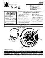
Orion
Brand: B-K lighting Pages: 2
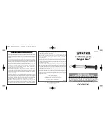
Bright Bar
Brand: Vector Pages: 2
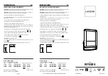
INTEGRA
Brand: LANZINI Pages: 2
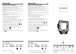
Q
Brand: LANZINI Pages: 2
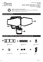
E1205-WH
Brand: Patriot Lighting Pages: 8
R1
Brand: LANZINI Pages: 2
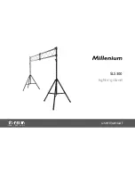
SLS300
Brand: Millenium Pages: 32
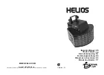
Helios
Brand: JB Systems Pages: 22
RBC
Brand: Acclaim Lighting Pages: 2
MINI-MICRO
Brand: B-K lighting Pages: 4
L360A
Brand: Eagle Pages: 3
EE600
Brand: hager Pages: 44

250S
Brand: g-lites Pages: 20
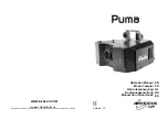
Puma
Brand: JB Systems Pages: 17
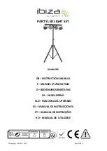
DJLIGHT65
Brand: Ibiza Pages: 45
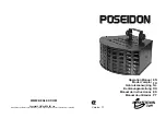
Poseidon
Brand: JBSYSTEMS Light Pages: 21
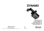
Dynamo
Brand: JBSYSTEMS Light Pages: 25


