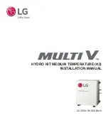
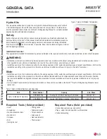
background image

HYDRO KIT MEDIUM TEMPERATURE (K2)

INSTALLATION MANUAL

42,000 to 96,000 Btu/h

Summary of Contents for MULTI V HYDRO KIT ARNH423K2A4

Page 1: ...HYDRO KIT MEDIUM TEMPERATURE K2 INSTALLATION MANUAL 42 000 to 96 000 Btu h ...

Page 2: ...reference Content familiarity is required for proper installation The instructions included in this manual must be followed to prevent product malfunction property damage injury or death to the user or other people Incorrect operation due to ignoring any instructions will cause harm or damage The level of seriousness is classified by the symbols described by the summary list of safety precautions ...

Page 3: ...nt Piping Connections 29 Insulation 30 31 Refrigerant Piping System Insulation 30 Installing the Condensate Piping 32 Installing the Water Circuit 33 47 Connections Guidelines Water Quality 33 Antifreeze Additives 34 Water Circuit Components 35 42 Application Options 43 47 Wiring 48 72 General Information Separating Wiring and Cables 48 Power Wiring Communication Cable Terminal Connections 49 3RZH...

Page 4: ...gerating and Air Conditioning Engineers Standard 15 If the UHIULJHUDQW OHDNV DQG VDIHW OLPLWV DUH H FHHGHG LW ZLOO UHVXOW LQ SHUVRQDO LQMXULHV RU GHDWK IURP R JHQ GHSOHWLRQ The Hydro Kit must be installed indoors do not install the unit outside or in a highly humid environment 7KHUH LV ULVN RI UH HOHFWULF VKRFN H SORVLRQ DQG SK VLFDO LQMXU RU GHDWK Dispose the packing materials safely Packing mate...

Page 5: ...ays check for system refrigerant leaks after the unit has been installed or serviced Low refrigerant levels will cause product failure Properly insulate all cold surfaces to prevent sweating Cold surfaces such as uninsulated piping can generate condensate that will drip and cause a slippery surface condition and or water damage to walls The Hydro Kit must be kept in an upright and level position d...

Page 6: ... the nearest disconnect before servic ing the equipment Use appropriate meters and equipment to verify the power is off Electrical shock can cause physical injury or death Do not use damaged or loose power wiring Do not modify or extend the Hydro Kit s power wiring Ensure that the power wiring will not be pulled nor weight be placed on the power wiring 7KHUH LV D ULVN RI UH HOHFWULF VKRFN SK VLFDO...

Page 7: ...ded the authorization 7KHUH LV D ULVN RI UH HOHFWULF VKRFN SK VLFDO LQMXU RU GHDWK 3URYLGH VXI FLHQW HOHFWULFDO V VWHP SURWHFWLRQ DJDLQVW lighting strikes 7KHUH LV D ULVN RI UH HOHFWULF VKRFN SK VLFDO LQMXU RU GHDWK Turn the power off at the nearest disconnect before servicing the equipment Electrical shock will cause physical injury or death Verify all power ground and communications wires and ca...

Page 8: ...the power supply during operation Do not disconnect the power supply of the Hydro Kit if op eration needs to be stopped Always turn Hydro Kit off using the wired remote controller 7KH SODWH KHDW H FKDQJHU ZLOO EXUVW LI WKH FRPPXQLFDWLRQ EHWZHHQ GUR LW DQG WKH RXWGRRU XQLW LV GLVFRQQHFWHG 7KHUH LV ULVN RI UH HOHFWULF shock physical injury and or death Do not place a heater or other appliances near ...

Page 9: ...OLIIV 1 OO ULJKWV UHVHUYHG LV D UHJLVWHUHG WUDGHPDUN RI RUS Unit Nomenclature ARN H 42 3 K2 A Generation 4 Fourth Electrical Ratings 3 208 230V 60Hz 1Ph 42 42 000 96 96 000 Type H Hydro Kit Family ARN Multi V Indoor Unit Refrigerant R410A K2 Hydro Kit Water Heater Cooler Feature A Basic Nominal Cooling Capacity in Btu h Model 4 GENERAL DATA ...

Page 10: ...sonnel trained in the required construction mechanical electrical and or other disciplines Connecting cable power and control Pipes vapor line and liquid line with insulation Condensate piping Level Screwdriver Electrical lineman pliers Electric drill Holesaw Drill Flaring tool set Tubing cutter Tube pipe reamer Torque wrenches Allen wrench Gas leak detector Thermometer WARNING Installation work m...

Page 11: ...vided for Each Hydro Kit Description Quantity Image Remote Controller and Cable 1 Indirect Hot Water Storage Tank Sensor Well 1 Indirect Hot Water Storage Tank Sensor 1 Strainer 1 Independent Power Module 1 Conduit Mounting Plate 2 Screws for Remote Controller Installation 4 Screws for the Conduit Mounting Plate 4 Parts OK See Accessories on pages 18 20 for a list of compatible Hydro Kit optional ...

Page 12: ... depletion potential ODP is 0 WARNING R QRW SODFH WKH UHIULJHUDQW F OLQGHU LQ GLUHFW VXQOLJKW 5HIULJHUDQW F OLQGHU ZLOO H SORGH FDXVLQJ VHYHUH LQMXU RU GHDWK Because R410A is a combination of R32 and R125 the required additional refrigerant must be charged in its liquid state If the refrigerant is charged in its gaseous state its composition changes and the system will not work properly Do not hea...

Page 13: ...RW DYDLODEOH ZKHQ WKH GUR LW LV FRQ JXUHG IRU FRQGLWLRQHG VSDFH control using a conventional thermostat 2 Each Hydro Kit unit group must be connected to the same outdoor unit Hydro Kit units within the same group must have the same DIP switch settings The only DIP switch that can differ is the group control setting switch where one Hydro Kit will be the master and the remaining Hydro Kit units wil...

Page 14: ...ial Type 316 Stainless Brazed Plate 316 Stainless Brazed Plate Rated Water Flow GPM 10 4 24 3 Rated Pressure Drop3 ft wg 13 7 23 1 Range of Flow GPM 5 3 10 4 8 24 3 Waterside Volume US Gallons 0 31 0 58 Water Side Design Pressure psig 640 640 Piping Liquid Line in OD 3 8 Braze 3 8 Braze Vapor Line in OD 5 8 Braze 7 8 Braze Condensate Line in ID 1 MPT 1 MPT Water Inlet Outlet in ID 1 MPT 1 MPT Tabl...

Page 15: ...llation manual 2 Power to the unit must be grounded in accordance with all applicable state local and national regulations and codes 3 All field supplied electrical components and materials must comply all applicable state local national and international regulations and codes 3D View 22 15 16 582 6 5 16 161 6 9 16 167 4 9 16 116 1 3 8 35 5 7 16 138 2 3 4 70 13 15 16 354 8 13 16 224 2 3 4 70 15 9 ...

Page 16: ...ion Manual XH WR RXU SROLF RI FRQWLQXRXV SURGXFW LQQRYDWLRQ VRPH VSHFL FDWLRQV PD FKDQJH ZLWKRXW QRWL FDWLRQ OHFWURQLFV 8 6 QF QJOHZRRG OLIIV 1 OO ULJKWV UHVHUYHG LV D UHJLVWHUHG WUDGHPDUN RI RUS Wiring Diagram ARNH423K2A4 ARNH963K2A4 GENERAL DATA 11 19 ...

Page 17: ...refrigerant cycle Water Inlet Temperature Sensor CN_TH3 Water Inlet and Water Outlet sensors are connected to 4 pin connector CN_TH3 Water Outlet Temperature Sensor Table 6 Hydro Kit Piping Schematic Legend S Water Inlet Water Outlet Vapor Line Liquid Line Water Inlet Temp Sensor Water Outlet Temp Sensor Vapor Line Temp Sensor Strainer Strainer Electronic Expansion Valve Plate Heat Exchanger Cooli...

Page 18: ...ANNOT be con nected to CH TH4 at the same time Accessory Model No Connection Description Use Wired Remote Extension Cable1 PZCWRC1 33 foot extension cable assembly Extends the length of the Hydro Kit Unit Controller communications cable beyond 33 feet cannot be used to extend tank sensor cable length Solar Heating System Interface Kit PHLLA CN TH4 Solar Kit includes solar heating system tank senso...

Page 19: ...er model Monitors and or controls optional the Hydro Kit based on the conditioned space temperature Mechanical Thermostat TB 17 18 19 20 Harness Plug C to A Single stage heating only Monitors and or controls optional the Hydro Kit based on the conditioned space temperature Hydro Kit Circuit 3 Way Diverting Valve TB 8 9 10 208 230 60 1 Valve A 208 230 60 1 3 wire SPDT Diverting valve circulates wat...

Page 20: ...VSHFL FDWLRQV PD FKDQJH ZLWKRXW QRWL FDWLRQ OHFWURQLFV 8 6 QF QJOHZRRG OLIIV 1 OO ULJKWV UHVHUYHG LV D UHJLVWHUHG WUDGHPDUN RI RUS Table 10 LG Optional Controllers Sold Separately ACCESSORIES Controller Model No LG MultiSITE Communications Manager PBACNBTR0A AC Smart 5 PACS5A000 ACP 5 PACP5A000 ACP LonWorks PLNWKB100 ...

Page 21: ...UHFW WKHUPDO UDGLDWLRQ IURP RWKHU KHDW VRXUFHV R QRW LQVWDOO WKH XQLW LQ D ORFDWLRQ ZKHUH DFLGLF VROXWLRQ DQG VSUD VXOIXU DUH RIWHQ XVHG R QRW XVH WKH XQLW LQ HQYLURQPHQWV ZKHUH VXOIXULF JDV LV SUHVHQW R QRW LQVWDOO WKH XQLW QHDU D KHDW RU VWHDP VRXUFH RU ZKHUH FRQVLGHUDEOH DPRXQWV RI RLO LURQ SRZGHU RU IORXU DUH XVHG 7KHVH PDWHULDOV ZLOO JHQHUDWH FRQGHQVDWH FDXVH D UHGXFWLRQ LQ KHDW H FKDQJHU HII...

Page 22: ...LQDO SDFNLQJ PDWHULDOV DUH QRW UHWDLQHG IRU WKH FODLPV DGMXVWRU WR LQVSHFW DOO RXU VXSHUYLVRU RQ KRZ WR SURFHHG ZLWK OLQJ D IUHLJKW FODLP DQG WR RUGHU D UHSODFHPHQW XQLW 1 Before opening check the unit model number on the box Verify it is the correct capacity unit type and voltage Refer to the Nomenclature Chart in this manual 2 Place the box on a solid surface right side up 3 Cut the white reinfo...

Page 23: ...W WKH XQLW ZLWK WKH FHQWHU RI JUDYLW FHQWHUHG DPRQJ WKH OLIWLQJ VWUDSV 7KHUH LV D ULVN RI WKH SURGXFW IDOOLQJ DQG FDXVLQJ SK VLFDO LQMXU LIW WKH RXWGRRU XQLW IURP WKH EDVH DW VSHFLILHG ORFDWLRQV 6XSSRUW WKH RXWGRRU XQLW DW D PLQLPXP RI VL SRLQWV WR DYRLG VOLSSDJH IURP WKH ULJJLQJ DSSDUDWXV DQG XVH D PLQLPXP RI WKUHH OLIWLQJ VWUDSV 7KHUH LV D ULVN RI WKH SURGXFW IDOOLQJ DQG FDXVLQJ SK VLFDO LQMXU 8...

Page 24: ...R LW I LW GRHV QRW KDYH VXIILFLHQW VWUHQJWK WKH GUR LW ZLOO IDOO DQG FDXVH GDPDJH WR WKH XQLW QVXUH WKDW WKH IORRU FKRVHQ ORFDWLRQ KDV HQRXJK VSDFH IRU SLSHV DQG ZLULQJ WKH FRQGHQVDWH GUDLQ FRQQHFWLRQ DQG WKH IORRU GUDLQ P SURSHU LQVWDOODWLRQ FDQ UHVXOW LQ XQLW PDOIXQFWLRQ QVXUH WKH GUR LW LV ILUPO DWWDFKHG WR WKH IRXQGDWLRQ Q GHILFLHQF LQ LQVWDOODWLRQ ZLOO FDXVH XQLW WR IDOO UHVXOWLQJ LQ GDPDJH W...

Page 25: ...sensors and third party thermostats optional sold separately If the Hydro Kit s water flow will be controlled by monitoring the conditioned space temperature proper Hydro Kit operation depends on the location of the controller sensor thermostat A good location will be to protect the controller sensor thermostat away from direct sunlight high humidity water vapor and where it could be directly expo...

Page 26: ...System does not operate properly Solutions Remove moisture from the piping Piping ends should remain capped until connections are complete Do not install piping on a rainy day Connect piping properly at the unit s side Remove caps only after the piping is cut the burrs are removed and after passing the piping through the walls Evacuate system to a minimum of 500 microns and insure the vacuum holds...

Page 27: ...itrogen prior to assembly 4 Use adapters to assemble different sizes of pipe 5 Always use a non oxidizing material for brazing Do not use flux soft solder or anti oxidant agents If the proper material is not used oxidized film will accumulate and clog or damage the compressors Flux can harm the copper piping or refrigerant oil 6 Use a tubing cutter do not use a saw to cut pipe De bur and clean all...

Page 28: ...an be used as long as they do not compress the pipe insulation Place a second layer of insulation over the pipe insulation jacket to prevent chafing and compression of the primary insulation in the confines of the support clamp A properly installed pipe system will have sufficient supports to avoid pipes from sagging during the life of the system As necessary place supports closer for segments whe...

Page 29: ...5 I D 3 8 9 52 I D 3 8 9 52 I D 3 8 9 52 Liquid Pipe Dimensions AJR54072930 AJR54072928 Ports are numbered right to left on the new PRHR 3A heat recov ery units Refer to the specific Air Source Water Source Installation Manual for detailed information about Heat Recovery Unit installation Figure 10 Y Branch Kit for Twinning Heat Recovery Ports When Pre Commissioning Addressing Systems with Hydro K...

Page 30: ...h a top cover and meet local codes LG provided Y branches are shipped from the factory with pre formed peel and stick foam insula tion jackets with a 1 84 lb ft 3 density 1 2 inch thickness and meet UL94 MF 1 flammability The design engineer must perform calculations to determine if the factory supplied insulation jackets are sufficient to meet local codes and avoid sweating Add additional insulat...

Page 31: ...tion 1 Typical Conditioned Location 2 Special Conditioned Location 3 Typical Unconditioned Location 4 Special Unconditioned Location Liquid pipe ø1 4 inches 1 2 inches 1 2 inches 1 2 inches 1 2 inches ø3 8 inches LQFKHV 1 2 inches 1 2 inches 1 2 inches 1 2 inches Vapor pipe ø3 8 inches 1 2 inches 3 4 inches 3 4 inches 1 inch ø1 2 inches ø5 8 inches ø3 4 inches ø7 8 inches ø1 inch ø1 1 8 inches 3 4...

Page 32: ... Kits do not include internal drain pumps the units use grav ity drains to remove condensate If a condensate pump is required it is field provided and installed external to the Hydro Kit frame The condensate drain connection is 1 0 MPT For the drain piping size use the same diameter as the product connected or larger Condensate piping must slope about 1 50 to 1 100 downward and not include any tra...

Page 33: ...ds Ensure all piping connections L shaped elbows T shaped fittings diameter reducers are tight and free from water leaks Seal all piping connections with Teflon tape sealant joint compound rubber bushings etc Insulate the piping to prevent heat loss and to avoid generating condensate Operation time of flow valves examples three way valve or two way valve must be less than 90 seconds Connections Gu...

Page 34: ...990 0 985 0 979 0 974 Ethylene Glycol 0 993 0 985 0 977 0 969 0 961 Propylene Glycol 0 966 0 973 0 960 0 948 0 935 Table 14 Cooling Capacity Correction by Antifreeze Chart Table 15 Heating Capacity Correction by Antifreeze Chart Table 16 Water Pressure Drop Correction Factors Type Antifreeze Concentration Level by Weight 10 20 30 40 50 Methanol 1 023 1 057 1 091 1 122 1 160 Ethylene Glycol 1 024 1...

Page 35: ...DV HQWHUHG WKH ZDWHU FLUFXLW GXULQJ LQVWDOODWLRQ 6 Install an air vent air separator 5 in the section of the water pipe with the highest elevation This prevents air bubbles from forming in the pipe system that would impede water flow WARNING I WKHUH LV D ORW RI DLU LQ WKH ZDWHU FLUFXLW DQG WKH ZDWHU ÀRZ GURSV UURU RGH DSSHDUV RQ WKH GUR LW RQWUROOHU GLVSOD I WKH ZDWHU ÀRZ drops there is the potent...

Page 36: ...stem to prevent condensation Use proper size insulation as outlined by insulation manufacturer and by the design engineer Install water tank Install floor cooling heating Field Installation Union 2 Air Vent 5 Thermometer 6 Drain Pipe 1 Service Port 3 Strainer 4 Drain Valve 8 Shut Off Valve 9 Outlet Water or Inlet water Pressure Meter 7 Hydro kit Pressure Relief Valve 10 Shut Off Valve 9 Thermomete...

Page 37: ...it Model No MEG61846102 For Those Applications With An Indirect Water Storage Tank Figure 19 Indirect Water Storage Tank Sensor Well Installation If the indirect water storage tank includes an existing sensor well that can accommodate the LG factory provided sensor see next page use it and skip this procedure 1 Drill and thread a 1 2 FPT hole in the tank wall at the tank manu facturer s recommende...

Page 38: ...nstallation instructions on the previous page 2 Remove the sensor and cable from the well Loosen and remove the keeping nut at the entry of the well housing and remove the sensor from the well by gently pulling on the sensor cable Slide the keeping nut up the sensor wire so it will not get misplaced Threads must face the sensor bulb 3 Apply a generous portion of thermal paste to the sensor and in ...

Page 39: ...anel area If the cable passes through an access hole with sharp edges install field supplied protective grommets to avoid damage to the cable 4 Find the red CN TH4 connector on the Hydro Kit PCB Inspect the leads and pins of the sensor cable plug looking for bent pins and loose connections between the wire leads and the metal pins If not damaged insert the sensor cable plug into CN TH4 I D GDPDJHG...

Page 40: ...nches away from any power wiring Depending on the current draw of nearby wiring the minimum clearance distance will have to be increased For more information regarding power wiring communications cable clearances see the Wiring section Refer to the figure below when installing the Solar Heating System Interface Kit For more detailed information see the Solar Heating System Interface Kit Installati...

Page 41: ...tank for easy access and maintenance To remove any impurities and ensure clean hot water thoroughly wash out the inside of the domestic hot water tank before and after installation When using the Hydro Kit in domestic hot water tank applications a recirculation pump is recommended for install A recirculation pump helps prevent cold water at the end of the hot water supply from infiltrating the wat...

Page 42: ... it can result in performance deterioration or system failure If the water supply is hard the plate type heat exchanger of the Hydro Kit could become dam aged or system failure could occur If the Hydro Kit displays a CH24 or CH180 error code it is possible that the interior of the plate type heat exchanger is partially frozen If this occurs resolve the partial freezing issue and then operate the H...

Page 43: ... Domestic Hot Water Floor Heating System Schematic Verify that Hydro Kit PCB DIP Switch Group 2 is set correctly for water tank domestic hot water floor heating installation applications this application is the factory default setting Refer to the Hydro Kit DIP Switch Settings pages in the Pre Commissioning section The domestic hot water tank is for hot water applications and uses the indirect hea...

Page 44: ...Water Supply Wired Remote Controller Wi Fi Module Flow Switch in Hydro Kit Hydro Kit Balancing Valve with Flow Meter Strainer Water Pump Automatic Air Separator Magnetic Dirt Separator Pressure Safety Release Valve Service Port Drain Valve Service Port Drain Valve Pressure Meter Check Valve Shut Off Valve Shut Off Valve Shut Off Valve Shut Off Valve Expansion Tank Water Tank Temperature Sensor Dom...

Page 45: ...oling Fan Coil Unit Not Use Open Fan Coil Unit Use Close Heating None No Control QVWDOO D EDODQFLQJ YDOYH ZLWK D ÀRZ PHWHU recommended to ensure that nominal ZDWHU ÀRZ UHPDLQV QHDU I WKH ZDWHU ÀRZ UDWH LV WRR ORZ RU WRR KLJK the plate heat exchanger could freeze and burst or system capacity could be reduced Field Supplied LG Supplied Drain Water Supply Fan Coil Unit RROLQJ ĺ ORVH Remote Temperatur...

Page 46: ... its water For sensing air temperature at a specific area choose a remote temperature sensor or a wired remote controller depending on the Hydro Kit PCB DIP Switch Group 3 setting Refer to the Hydro Kit PCB DIP Switch Settings pages in the Pre Commissioning section When installing a floor heating system to measure room temperature use the Hydro Kit controller or a remote temperature sensor sold se...

Page 47: ...the mixing tank will freeze and burst resulting in physical injury and or death If the application combines the Hydro Kit with a mixing tank one water pump must be installed between the Hydro Kit and the mixing tank another ZDWHU SXPS PXVW EH LQVWDOOHG EHWZHHQ WKH PL LQJ WDQN DQG LQGRRU FRPSRQHQWV IDQ FRLO XQLWV ÀRRU KHDWLQJ UDGLDWRU HWF 7KHVH SXPSV PXVW LQWHU face with the Hydro Kit and always mu...

Page 48: ...e to carefully read and follow all instruc tions in this manual can result in equipment malfunction or property damage Consider ambient conditions temperature direct sunlight inclement weather etc when selecting installing and connecting the power wiring Properly ground all outdoor units indoor units and Hydro Kits Ground wiring must always be installed by a qualified technician Improperly ground ...

Page 49: ...n appropriately sized screwdriver for tightening the terminals Do not overtighten the connections overtightening will damage the terminals If ring terminals or fork terminals are not available then Do not terminate different gauge wires to the power terminal block Slack in the wiring will generate heat When terminating wires of the same thickness follow the instructions demonstrated in the figures...

Page 50: ...regulations related to electrical equipment and wiring and following the instructions in this manual Generated overcurrent will include some amount of direct current Using an oversized breaker or fuse will result in electric shock physical injury or death Use the appropriate type of overcurrent protection Generated overcurrent will include some amount of direct current and if the appropriate type ...

Page 51: ...o Kit and the LG Hydro Kit Controller included with the Hydro Kit or third party thermostat sold separately is 164 feet 50 m Maximum allowable communication cable length between the Hydro Kit and the LG manufactured water storage tank sensor is 39 feet 12 m use factory provided sensor cable Maximum allowable communication cable length between the Hydro Kit and the LG manufactured dry contact sold ...

Page 52: ...trol box cover 7 Route the power wiring and communications cable inside the control box 5HIHU WR DOO HOHFWULFDO GDWD DQG SRZHU ZLULQJ FRPPXQLFDWLRQV FDEOH VSHFL FDWLRQV EHIRUH SUR ceeding Incorrect installation will lead to product malfunction and damage All power wiring and communications cable installation must be performed by authorized service providers working in accordance with local state a...

Page 53: ...shield of the communications cable to the Hydro Kit indoor unit frame or other grounded entities of the building Failure to properly provide a NEC approved earth ground will result in electric shock physical injury or death Never connect the Hydro Kit controller or other central controllers such as AC Smart PDI or the LG building management system gateway products to the communications cable betwe...

Page 54: ...nd following the instructions in this manual Failure to do so will lead to electric shock and bodily injury or death Be sure that main power to the unit is completely off before pro ceeding Follow all safety and warning information outlined at the beginning of this manual Failure to do so will cause electric shock and bodily injury The information contained in this manual is intended for use by a ...

Page 55: ...nd the product specifications Never touch wiring or install accessories with wet hands When drilling holes for the communication cable and the screws take care not to damage wiring that is routed through the wall There is risk RI UH HOHFWULF VKRFN H SORVLRQ DQG SK VLFDO LQMXU RU GHDWK See the Installation section for guidelines on where to place the controller The controller is designed to be surf...

Page 56: ... in a group one wired remote controller controlling multiple Hydro Kits use one or multiple Group Control Cable Kits sold separately Group Control Cable Kits consist of three 3 cables One pigtail cable One Y cable One 39 foot 12 m long extension cable Use one 1 Group Control Cable Kit for each Hydro Kit in the group a pigtail cable is not required at the last Hydro Kit Slave unit in the group Grou...

Page 57: ...and the communications cable from the controller to the Y cable A wireless remote controller can be used at the same time as Group Controller A Dry Contact and a Central Controller also can be connected at the same time but only the address of the Master Hydro Kit can be recognized Slave Hydro Kits cannot be individually controlled by the Dry Contact or Central Controller these will follow Master ...

Page 58: ...LOO GDPDJH WKH ZLULQJ DQG will lead to product malfunction 0DLQWDLQ WZHQW PLQXWHV RI FRQWLQXRXV SRZHU WR WKH SRZHU PRGXOH NLW WR HQVXUH WKDW WKH 9 LV IXOO FKDUJHG DQG FDQ FORVH SURSHUO Refer to the Independent Power Module Installation Manual for more detailed information 1 Turn power off at the circuit breaker 2 Open the Hydro Kit front panel control box cover 3 Assemble the cover of the Independ...

Page 59: ... LQMXU DQG RU GHDWK 3 Route the sensor well cable through the Hydro Kit frame and into the control panel area If the cable will pass through an access hole with sharp edges install field supplied protective grom mets to avoid damaging the cable 4 Find the red CN TH4 connector on the Hydro Kit PCB Inspect the leads and pins of the sen sor well cable plug looking for bent pins and loose connections ...

Page 60: ...f the communications cable between the sensor and the Hydro Kit is too long do not cut Coil any spare cable tie wrap it and leave it near the Hydro Kit I WKH GLVWDQFH EHWZHHQ WKH 5HPRWH 7HPSHUDWXUH 6HQVRU DQG WKH GUR LW LV PRUH WKDQ IHHW P XVH RQH RU PRUH IRRW P WHQVLRQ DEOH VROG VHSDUDWHO 7KH PD LPXP OHQJWK RI WKH FDEOH FDQQRW H FHHG IHHW P Do not damage the quick connect plugs Do not remove and ...

Page 61: ...ame access hole as the power input cable Do not cut the sensor cable If the cable is longer than necessary coil and secure excess cable 8 Insert the connector of the remote temperature button sensor cable into the CN ROOM connector on the PCB 9 Use a cable tie or other method to secure the remote temperature button sensor cable inside the Hydro Kit Do not allow strain on the cable 10 Reinstall the...

Page 62: ...t be installed for each Hydro Kit For more information about the LG Wi Fi Module see www lghvac com Connecting the Wi Fi Module 1 Verify that the power to the Hydro Kit is OFF 2 Remove the front panel and control box cover to the Hydro Kit 3 Locate CN WF on the main PCB of the Hydro Kit 4 Route the Wi Fi USB cable through the bottom of the control panel and insert its plug into CN WF If a longer c...

Page 63: ...curred A field supplied binary signal could be triggered using a timer keycard switch door switch motion detector or an occupancy sensor To install a Dry Contact see the Dry Contact submittals and or installation manuals on www lghvac com or contact your LG representative Connect the Dry Contact to Terminal CN CC on the Hydro Kit PCB See the Pre Commissioning section for function codes and instruc...

Page 64: ...cognize that an external control ler is installed Enter installer setting mode on the Hydro Kit controller and set the function code Figure 62 X Relay See the Pre Commissioning section for function codes and instructions on accessing Installer mode that will be needed to set up other Hydro Kit accessories Figure 63 Connecting the External Controller Connecting an External Controller Use the CN_EXT...

Page 65: ...nction Follow manufacturers installation instructions for the field supplied sold separately third party components such as valves thermostats and pumps Check each accessory carefully before installing Improper installation will lead to product malfunction and damage Check the labels on the Hydro Kit PCB and terminal blocks before connecting all accessory wiring cables Ensure connections are prope...

Page 66: ...stic water tank 3 Flow B Water flow from the Hydro Kit unit to the floor water circuit W Live signal Water tank heating from PCB to three way valve U Live signal Floor heating from PCB to three way valve N Neutral signal from PCB to three way valve Three Way Valve W U N Three Way Valve A BR WH BL 8 L 9 L1 10 N Table 23 7KUHH D 9DOYH 6SHFL FDWLRQV Wire to Terminals 8 to 10 Three Way Valve Figure 65...

Page 67: ... SXPS 11 12 L N Pump Main Relay Pump Connecting the Circuit Water Pump Interlock WARNING Always have power off before installing accessories Failure to do so will cause electric shock physical injury and or death Never operate Hydro Kit outside of the operational parameters as outlined in this manual and the product specifications Failure to do so will cause electric shock physical injury and or d...

Page 68: ...aller mode that will be needed to set up Hydro Kit accessories A two way isolation valve is required to stop the water flow to portions of the Hydro Kit s water piping system when the Hydro Kit operates in cooling mode Chilled water flow will damage building materials if condensate was allowed to form on the surfaces Type Power Operating Mode Supported NO Two wire 1 230 V AC Close water flow Yes O...

Page 69: ...f the chosen thermostat does not have both of the features listed above the Hydro Kit will not operate properly Heating Cooling Thermostat must be able to send cooling and heating signals immediately when the temperature condition is met There can be no delay in trigger timing Some electromechanical thermostats have an internal time delay to protect the compressor If the chosen electromechanical t...

Page 70: ...K DV YDOYHV IDQ FRLO units etc If connected it will seriously damage the main PCB as sembly Thermostat Wire to Terminals 17 to 20 L N C H Heating Cooling Heating Only and Heating Cooling Figure 72 Hydro Kit Terminal Connections for Third Party 208 230 V Thermostats Figure 73 Wiring for the Heating Only Thermostat Figure 74 Wiring for the Heating Cooling Thermostat Wiring the Third Party Thermostat...

Page 71: ...f power wiring and communications cable connec WLRQV DUH VZDSSHG LPSURSHUO LQVWDOOHG LW ZLOO FDXVH HOHFWULF VKRFN UH SK VLFDO LQMXU RU GHDWK Test the power wiring and communications cable for incorrect wiring before any power is applied The power wiring and communications cable con nections are swapped improperly installed the Hydro Kit will be damaged Using a multimeter measure the resistance acr...

Page 72: ...e of the operational parameters as outlined in this manual and the product specifications Never touch wiring or install accessories with wet hands KHQ GULOOLQJ KROHV IRU WKH FRPPXQLFDWLRQ FDEOH DQG WKH VFUHZV WDNH care not to damage wiring that is routed through the wall 7KHUH LV ULVN RI UH HOHFWULF VKRFN H SORVLRQ DQG SK VLFDO LQMXU RU death See the Installation section for guidelines on where to...

Page 73: ...s in the handy box using spray foam or similar insulation material approved by all applicable codes 5 Attach the top of the controller to the top of the installation plate Verify that the controller is level and secure 6 Plug the male connection on the controller into the female end of the communi cations cable 7 Connect the Hydro Kit controller cable to terminal CN REMO on the Hydro Kit PCB 8 Gui...

Page 74: ...n Cool Hydro Kit provides cool water to use for desired application Heat Hydro Kit provides hot water to use for desired application example floor heating or domestic hot water AI Auto Heating setpoint is automatically determined by a pre defined temperature profile AI Auto Operation AI Auto Operation applies only to heating To save energy and provide high comfort levels the set temperature will f...

Page 75: ...e Domestic Hot Water Tank Temperature Domestic hot water tank temperature setting is available if a domestic hot water tank is installed 113 Figure 83 Temperature Setting Screen Table 28 Temperature Setting Options Domestic Hot Water Heating Operation Sets the function to use or not to use an installed domestic hot water tank This function is not used when the domestic hot water tank is not instal...

Page 76: ...K button to select the setting list screen 3 2Q WKH VHWWLQJ OLVW VFUHHQ SUHVV WKH 8S ȁ DQG RZQ 9 EXWWRQV WR turn the Low Noise Mode On or Off 4 Press the Left and Right buttons to select the parts press the 8S ȁ DQG RZQ 9 EXWWRQ WR DGMXVW WKH WLPH HFDXVH RZ 1RLVH 0RGH DOORZV WKH GUR LW WR IXQFWLRQ DW D ORZHU FDSDFLW WKH KHDWLQJ RU FRROLQJ RSHUDWLRQ ZLOO DOVR EH UHGXFHG H DZDUH RI WKLV ZKHQ D FHUWD...

Page 77: ...s only available on some products Wi Fi Pairing activates the AP mode function of the Wi Fi Module connected to the Hydro Kit 1 On the main menu screen press the Left and Right buttons to select the desired setting category 2 Press the OK button to select the setting list screen 3 2Q WKH VHWWLQJ OLVW VFUHHQ SUHVV WKH 8S ȁ DQG RZQ 9 EXWWRQV WR WXUQ L L 3DLULQJ 2Q RU 2II OK OK OK CONTROLLER OPERATIO...

Page 78: ...rost operation for the outdoor unit 1 On the main menu screen press the Left and Right buttons to select the desired setting category 2 Press the OK button to select the setting list screen 3 2Q WKH VHWWLQJ OLVW VFUHHQ SUHVV WKH 8S ȁ DQG RZQ 9 EXWWRQV WR WXUQ HIURVW 0RGH 2Q RU 2II Setting Values STEP0 Defrost Mode Not Used STEP1 Forced Snow Removal STEP2 Fast Defrost Setting STEP3 Forced Snow Remo...

Page 79: ... be set through the wired remote controller 1 On the main menu screen press the Left and Right buttons to find the Lock Setting 2 Press the OK button to select the Lock Setting 3 2Q WKH RFN 6HWWLQJ OLVW SUHVV WKH 8S ȁ DQG RZQ 9 EXWWRQV WR turn the corresponding lock function On or Off Mode Description All Lock Locks all button operation of the remote controller On Off Lock Locks the On Off button ...

Page 80: ...ect the date category 2 Press the OK button to access the date detail screen 3 After setting the date press the OK button to save the selection and return to the previous screen OK Timer Settings Time Setting Sets the time displayed on the remote controller 1 In the user setting list select the time category 2 Press the OK button to access the time detail screen 3 After setting the time press the ...

Page 81: ...er the corresponding setting If product operation is Off the simple timer turns On the operation after the corresponding setting If the simple timer operation is turned On Off before timer setting operation begins the timer setting will be removed OK Sleep Timer Sleep Timer operates the Hydro Kit before shutting off sleep mode for the set amount of time Sleep timer can be set while the Hydro Kit i...

Page 82: ...ally turns Off at the time set If Turn Off Reservation operation is turned on or off after the setting begins but before the timer operates the timer setting will not disap pear OK Turn On Reservation Hydro Kit automatically turns On at the time set If Turn On Reservation operation is turned on or off after the setting begins but before the timer operates the timer setting will not disap pear OK C...

Page 83: ...V WR FKHFN WKH FRUUHVSRQGLQJ GDWH V RWKHU WLPHU LQIRUPDWLRQ 5 Select the timer information and press the OK button to access the corresponding timer s edit screen Schedules and Edit The status of the timer schedule saved in the remote controller can be checked in the Schedules and Edit function 1 On the schedule list select daily schedule status 2 Press the OK button to access the daily schedule s...

Page 84: ...WKHUPRVWDW PDQXDO FDUHIXOO IRU ZRUNDURXQGV LI the product does not respond quickly 2 7KH WKHUPRVWDW VHW WHPSHUDWXUH UDQJH FDQ EH GLIIHUHQW WKDQ WKDW RI WKH GUR LW DQG LWV LQFOXGHG FRQWUROOHU KRRVH KHDWLQJ DQG FRROLQJ set temperatures to coincide with the set temperature ranges of the Hydro Kit How to Operate the Third Party Thermostat For information on how to turn the thermostat on and off set ta...

Page 85: ...e operation If the Hydro Kit is not configured precisely it will operate improperly or the performance will be degraded When the DIP switch is in the UP position it is ON when the DIP switch is in the DOWN position it is OFF Table 31 Hydro Kit DIP Switch Group 2 Settings and Descriptions Figure 102 Hydro Kit DIP Switch PCB Locations Description DIP Switch Group 2 Settings Function Default 1 2 3 4 ...

Page 86: ...physical injury and or death How to Enter Installer Setting Mode The Installer Setup Mode must be used to set the functionality of the remote controller and to customize the Hydro Kit settings DLOXUH WR FRUUHFWO FRQ JXUH IXQFWLRQDOLW WKURXJK WKH QVWDOOHU 6HWXS FRXOG FDXVH XVHU LQMXU RQ JXUDWLRQ PXVW EH GRQH E D WUDLQHG WHFKQLFLDQ DLOXUH WR FRUUHFWO FRQ JXUH IXQFWLRQDOLW WKURXJK WKH QVWDOOHU 6HWXS ...

Page 87: ...led Upper Limit 68 F 77 F 20 C 25 C Default 75 F 24 C Lower Limit 61 F 68 F 16 C 20 C Default 61 F 16 C Fan Coil Unit IS Installed Upper Limit 68 F 77 F 20 C 25 C Default 75 2 F 24 C Lower Limit 41 F 68 F 5 C 20 C Default 41 F 5 C Adjusts range of the Setting Leaving Water Temperature for cooling mode Air Heating Set Temp Upper Limit 75 F 86 F 24 C 30 C Default 86 F 30 C Lower Limit 61 F 71 6 F 16...

Page 88: ...Heating Water Type 0 1 2 3 Default 0 The temperature of the heating water can be adjusted according to the field environment preparing for heating claims 7 2Q 2II 9DULDEOH Cooling Air Type 0 1 2 3 Default 0 The temperature of the cooling air can be adjusted according to the field environment preparing for cooling claims 7 2Q 2II 9DULDEOH Cooling Water Type 0 1 2 3 Default 0 The temperature of the ...

Page 89: ... Emergency Stop Seta external input and output control Depends on DI DO set by customer using dry contact port of the Hydro Kit ODU Function Master Master Slave Default Sets the outdoor unit function to Master Slave Low Noise Mode Priority ODU Default RMC Sets the low noise mode control subject ODU Cycle Priority Not Use Default Use Enables or disables the standby mode of the Hydro Kit Use Externa...

Page 90: ...HUDWXUH FDQ EH XVHG DV WKH VHWWLQJ WHPSHUDWXUH 21 LI D 5HPRWH LU 6HQVRU LV LQVWDOOHG HQDEOHG DQG WKH 5HPRWH LU 6HQVRU RQQHFWLRQ LV VHW DV LU 7HPSHUDWXUH IWHU VHOHFWLQJ LU 7HPSHUDWXUH VHOHFW 5HPRWH RQWURO DQG GUR LW Dry Contact This function allows the Dry Contact Hydro Kit connection to operate under Auto Run mode or Manual mode with remote control panel Use the Dry Contact function for contact po...

Page 91: ...WXUH EHORZ CAUTION RQGHQVDWH ZLOO FDXVH D VOLSSHU FRQGLWLRQ ZKLFK FDQ UHVXOW LQ D IDOO DQG VXEVHTXHQW SK VLFDO LQMXU RQGHQVDWH FRXOG GDPDJH ÀRRUV DQG ZDOOV Air Heating Set Temperature Use to determine heating setting temperature range when air temperature is selected as setting temperature 6HWWLQJ LV RQO DYDLODEOH ZKHQ 5HPRWH LU 7HPSHUDWXUH 6HQVRU LV LQVWDOOHG DQG VHW SURSHUO Water Heating Set Tem...

Page 92: ...enerated by the compressor cycle Example If Minimum Temperature is set as 5 and Maxi mum Outdoor Temperature is set as 48 then Session A see figure at right will start when the water tank tempera ture is below 113 F 45 C If temperature is above 118 F 48 C then Session B will start Hysteresis Temperature difference from target domestic hot water temperature This value is required for frequent On an...

Page 93: ...also regarded as time gap between domes tic hot water tank heating cycle TH On Off Variable Heating Air Setting thermal on off air temperature difference for heating mode Setting TH On TH Off 0 9 F 0 5 C 2 7 F 1 5 C 1 1 8 F 1 C 3 6 F 2 C 2 3 6 F 2 C 5 4 F 3 C 3 5 4 F 3 C 7 2 F 4 C TH On Off Variable Heating Water Setting thermal on off water temperature difference for heating mode Setting TH On TH...

Page 94: ...n time in the system pump is not operating or is delayed in operating Forced Operation Water Pump If the water has not been circulating in the Hydro Kit water circuit for 20 to 180 hours default 20 hours this function will switch ON the pump and force the water to circulate for 1 to 10 minutes default 10 minutes Forced Operation function can be used to prevent the water in the circuit from freezin...

Page 95: ... the outdoor unit using a DIP switch change on its PCB Function Setting Low noise operation time menu is inactivated 2 Setting Low Noise Operation Using the Remote Controller Low noise operation DIP switch setting on the outdoor unit PCB is ignored Function Setting Low noise operation time menu is activated ODU Function Master 1 Setting the Master Outdoor Unit Low noise operation control subject c...

Page 96: ...t to highest are 0 9 followed by A F See complete list in table at right Hex Address Assignment Limitations There is a limit of 16 Members per Hex Group There is a limit of 16 Hex Groups per system There is a limit of 256 possible Member Identifiers per Central Control See Central Controller Communications Limitations Setting Central Control Addresses 1 9HULI SRZHU WR WKH ZKROH V VWHP LQFOXGLQJ LQ...

Page 97: ...r Unit Quantity as shown in the tables at right Group Number If the building operator wants to know which Hydro Kits indoor units are on each outdoor unit and multiple systems serve a building Assign a Group Number to each system If there are more than 16 indoor units on a system multiple Group Numbers will be necessary If the building owner wants to know which indoor units are on each floor Assig...

Page 98: ...to the Master Hydro Kit Do not restore power to the Master Hydro Kit this time It will be restored later 8 If the zone controller and associated communications cable has already been permanently mounted in place reattach cable wiring and obtain a loose zone controller with a communications cable to continue programming the Slave Hydro Kits see procedure below For the Slave Hydro Kit s in a Group S...

Page 99: ...etting Branch Port Group Main Master PCB SW01D Setting No Grouping 0 Group Control Branches Ports 5 6 and 7 8 8 Group Control Branches Ports 1 and 2 1 Group Control Branches Ports 1 2 and 5 6 9 Group Control Branches Ports 2 and 3 2 Group Control Branches Ports 1 2 and 7 8 A Group Control Branches Ports 3 and 4 3 Group Control Branches Ports 3 4 and 5 6 B Group Control Branches Ports 5 and 6 4 Gro...

Page 100: ...ual valve port detection For Hydro Kits 1 The numbers of the connected vapor and liquid pipes must match 2 QVXUH WKDW ZDWHU LV IORZLQJ LQ WKH GUR LW GXULQJ WKH 9DOYH 3RUW HWHFWLRQ SURFHGXUH Use Mode 1 if the water temperature is greater than 86 F 30 C Use Mode 2 if water temperature is less than 86 F 30 C 9DOYH 3RUW HWHFWLRQ SURFHGXUH HUURU ZLOO GLVSOD LI WKH WHPSHUDWXUH RI WKH SLSH GRHV QRW LQFUH...

Page 101: ...ppropriate If the flow switch is operating properly If the connection status is good If the power wiring and communication cable are completely connected I WKH LQVXODWLRQ UHVLVWDQFH EHWZHHQ WKH WHUPLQDO EORFN DQG JURXQG LV Pȍ RU DERYH ZKHQ PHDVXUHG ZLWK 9 PHJD WHVWHU Never check the insulation resistance on the control board terminal This will damage the control board Flow Switch Error Troubleshoo...

Page 102: ...hat foreign particles and air bubbles will enter the water piping system which will lead to the plate type heat exchanger freezing If it is essential to change the water piping first separate the water piping from the Hydro Kit Thoroughly clean the interior of the new piping to remove any foreign particles and then connect the piping to the Hydro Kit If the Hydro Kit will not be used for an extend...

Page 103: ...om could have been very hot or cold when the Hydro Kit was first turned on Allow time for the room to cool down or heat up before reaching operation setpoint Has the setting temperature been set incorrectly Unit operation is noisy Sound is from refrigerant flow Refrigerant flow may generate sound during operation start or stop Hydro Kit heat exchanger is generating sound During cooling operation a...

Page 104: ...The following sequencing of the LED lights will display during a fault display After the error code is identified based on the sequencing and color of the LED lights refer to the Error Code Troubleshooting Table on the next page for causes and resolutions If the sequencing code is a three digit number those codes are based on the outdoor unit and not on the Hydro Kit 6HH WKH RXWGRRU XQLW ZDWHU VRX...

Page 105: ...o Kit and outdoor unit PCB communications error No signal communications error between Hydro Kit and outdoor unit PCB 12 Inverter PCB error Inverter PCB is malfunctioning 13 Hydro Kit solar heat pipe temperature sensor error Solar heat pipe temperature sensor disconnected shorted or opened 14 Hydro Kit flow switch error Flow switch failed to close Check if water pipe operation is normal Check for ...

Page 106: ...QLW DPSOH RPSUHVVRU F FOH SUREOHPV PHUJHQF RSHUDWLRQ PRGH LV SHUIRUPHG E DQ RSWLRQDO HOHFWULF KHDWHU LI LQVWDOOHG QRWKHU IDXOW WKDW FRXOG RFFXU LV DQ 2SWLRQ DXOW ZKLFK KDV WR GR ZLWK DQ LQVWDOOHG DFFHVVRU H DPSOH DQ RSHUDWLRQ HUURU ZLWK WKH ZDWHU WDQN Q WKLV LQVWDQFH WKH 2SWLRQ DXOW LV DVVXPHG DV LI LW ZDV QRW LQVWDOOHG LQ WKH V VWHP When an Error Occurs 1 Unidentified Errors After an unidentified...

Page 107: ... SURWHFW WKH V VWHP KHQ WKH V VWHP H SHULHQFHV faults operation stops until the end user building supervisor decides on a course of action either to call a trained technician to troubleshoot and fix the issue or to begin emergency operation If the system is running in Emergency Operation mode automatic re start is disabled If there is a loss of power during Emergency Operation the system must be r...

Page 108: ...ondensate pipe insulation has been supplemented to prevent sweat ing ZKLOH RSHUDWLQJ LI WKH GUR LW XQLW LQVWDOOHG LQ DEQRUPDO HQYLURQPHQWDO FRQGLWLRQV 2SWLRQDO MRE FRQGLWLRQ VSHFLILF All refrigerant and chilled water pipes are independently insulated All insulation seams and joints are air tight Insulation is not compressed Double layer insulation is provided at pipe supports and wall penetra tion...

Page 109: ...HO SOXJJHG LQWR WKH VRFNHW RQ WKH GUR LW DOO 0RXQWHG RQWUROOHU RU WKH WKUHH VFUHZ terminals on the Hydro Kit Unit Controller Yellow to Y Red to R and Black to B Hydro Kit Control Panel N A Not Complete Complete GUR LW DOO 0RXQWHG RQWUROOHU FDEOH LV VHFXUHO SOXJJHG LQWR WKH 1 5 02 VRFNHW RQ WKH GUR LW main PCB If an optional remote temperature sensor was installed the associated cable is plugged in...

Page 110: ... Multi V Pre Commissioning Device Configuration Worksheet rev 20130619 3 Project Name Building ID Date AC Smart Static IP address System ID Page Mech Contractor Company Name MEP Project Mngr Name Pre Com Tech Name Ph email Ph Email IDU s Unit Tag Building Floor Room ID Type Model Serial System Address Central Control Address Group member ID or N A if not in a group Group Function M Master S Slave ...

Page 111: ...A4_11_19 6XSHUVHGHV 95 0 7 86B VRF IM BT 001 US_013M20 20001747 ISO 9001 2008 LG ELECTRONICS INC LG Electronics U S A Inc Air Conditioning Technologies 4300 North Point Parkway Alpharetta Georgia 30022 www lghvac com ...

Reviews: