


CEILING CASSETTE INDOOR UNIT
INSTALLATION MANUAL
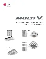
One-Way Models
• ARNU073TUD4
• ARNU093TUD4
• ARNU123TUD4
• ARNU183TTD4
• ARNU243TTD4
Four-Way 2
'
x 2
'
Models
• ARNU053TRD4
• ARNU073TRD4
• ARNU093TRD4
• ARNU123TRD4
• ARNU153TQD4
• ARNU183TQD4
Two-Way Models
• ARNU183TSA4
• ARNU243TSA4
Four-Way 3
'
x 3
'
Models
• ARNU073TAA4
• ARNU093TAA4
• ARNU123TAA4
• ARNU153TAA4
• ARNU183TAA4
• ARNU243TAA4
• ARNU283TAA4
• ARNU363TAA4
• ARNU423TAA4
• ARNU483TAA4


