background image

1

30” ELECTRIC RANGE

SERVICE MANUAL

MODEL: LSE4613ST

LSE4613BD

CAUTION

BEFORE SERVICING THE UNIT, READ THE SAFETY PRECAUTIONS IN THIS MANUAL.

P/NO : MFL37118342

September, 2015

Printed in Korea

Internal Use Only

Summary of Contents for LSE4613BD

Page 1: ...ELECTRIC RANGE SERVICE MANUAL MODEL LSE4613ST LSE4613BD CAUTION BEFORE SERVICING THE UNIT READ THE SAFETY PRECAUTIONS IN THIS MANUAL P NO MFL37118342 September 2015 Printed in Korea 삼 흥 정 판 Internal Use Only ...

Page 2: ...our dealer If the power cord is defective it must be replaced by a qualified service agent with a UL listed range cord Electrical leads and cables should not be allowed to touch the oven Rating plate is located on the left side of warming drawer The power supply of the appliance should be turned off when it is being repaired FORWARD LG Electronics assumes no responsibility for any repairs made on ...

Page 3: ...inPCB and key PCB assembly 3 5 Removing knob and infinite switch 3 6 Removing the ceramic glass cooktop and the surface element 3 7 Removing the cooling motor thermal disk and Rdoor switch 3 8 3 9 Removing the broil element 3 10 3 11 Removing the convection element fan blade and fan motor 3 12 Removing the oven light socket assembly 3 13 Removing the latch drive assembly 3 14 Removing the oven tem...

Page 4: ...ment 5 4 RF Cook top Element 5 4 Broil Speed broil 5 5 Warm Proof Easy clean 5 5 Bake Speed roast 5 5 COMPOSITION OF CONTROL 6 1 6 5 Wiring Diagram 6 1 Main PCB 6 3 Relay PCB 6 4 SMPS PCB 6 4 Encoder PCB 6 5 Touch PCB 6 5 Buzzer PCB 6 5 SVC TEST MODE 7 1 7 3 TROUBLE SHOOTING 8 1 8 2 Check the Failure Code 8 1 Failure Code Summary 8 2 CHECKING FLOW CHART BY FAILURE 9 1 9 20 Power Failed Dead No dis...

Page 5: ...es Failure to do so can result in severe personal injury death or electrical shock DO NOT touch heating elements or interior surfaces of oven Heating element may be hot even though they are dark in color Interior surfaces of an oven become hot enough to cause burns During and after use do not touch or let clothing or other flammable materials contact heating elements or interior surfaces of oven u...

Page 6: ...on WARNING DO NOT touch heating elements or interior surfaces of oven Heating element may be hot even though they are dark in color Interior surfaces of an oven become hot enough to cause burns During and after use do not touch or let clothing or other flammable materials contact heating elements or interior surfaces of oven until they have had sufficient time to cool Other surfaces of the applian...

Page 7: ... goes on or three long beeps sound oven is malfunctioning in the self clean mode Turn off or disconnect appliance from power supply and have serviced by a qualified technician VENTILATING HOODS Clean Ventilating Hoods Frequently Grease should not be allowed to accumulate on hood or filter When flaming foods under the hood turn the fan on OVEN Use Care When Opening Door Let hot air or steam escape ...

Page 8: ...Model Serial Number label and Tech Sheet locations are shown below Tech Sheet Location MODEL SERIAL NUMBER LABEL MODEL SERIAL NUMBER LABEL AND TECH SHEET LOCA AND TECH SHEET LOCATIONS TIONS Model Serial Number Location ...

Page 9: ...Door lockout Type Element Warming rack Oven Interior W x H x D Exterior Width Exterior Height Exterior Depth Net weight Lbs Kg Rating 29 Slide In STS Glass Touch Knob VFD Yes Yes Yes Setting 6 categories 1 Change hour mode on Clock 2 Convection Auto Conversion On Off 3 Oven Temp Adjust 4 Preheat alarm light On Off 5 Beeper volume High Low Mute 6 Select Fahrenheit or Celsius temperature Ceramic gla...

Page 10: ...element Rear element some model and fan operate during convection bake Convection bake should be used for cooking casseroles and roasting meats Oven should be preheated for best results when using convection bake Pans do not need to be staggered Difference between bake and convection mode is fan speed and amount of cycling time When cook with bake mode fan speed and amount of cycle tine is lower t...

Page 11: ...lement C LEFT REAR SINGEL CONTROL KNOB Use to control Left Rear Element D CENTER REAR WARM CONTROL KNOB Use to control Center Rear Element E RIGHT REAR SINGLE CONTROL KNOB Use to control Center Rear Element F RIGHT FRONT DUAL CONTROL Use to control Right Front Element G LOWER OVEN CONTROL KNOB Use to control lower oven H ELECTRIC OVEN CONTROL Use to control Electric Oven I HOT SURFACE INDICATOR LI...

Page 12: ...the Dual element There is one dual element located in the left front position Use the dual element as a dual or single element 1 Push in the appropriate knob 2 1 Turn the knob counterclockwise to use it as a Single element 2 1 Turn the knob clockwise to use it as a Dual unit To turn on the Dual element There is one dual element located in the left front position Use the dual element as a dual or s...

Page 13: ...ne illness 1 Turn the control knob to the On position NOTE For best results food on the warmer should be kept in its container or covered with a lid or aluminum foil to maintain food quality The warmer will not glow red like the other cooking elements The Warming Zone can be operated as a single element on some models CAUTION FOOD POISON HAZARD Bacteria may grow in food at temperatures below 140 F...

Page 14: ...n starts at the set time 5 Clock Lockout Press the button to Set the time of day Press and hold button for three seconds to lock the door and control panel 6 Timer On Off Press the button to set or cancel timer on oven 7 Oven Light Press the button to turn oven light on or off 8 WSetting Press the button to select and adjust oven settings 9 Press the plus button to increase cooking time or oven te...

Page 15: ...ory 1 CHANGE HOUR MODE ON CLOCK 1 Set the oven mode knob to the Off position 2 Press Setting 3 Press plus or minus to set the desired hour mode on the clock 4 Press Start to accept the desired change 2 CONVECTION AUTO CONVERSION 1 Set the oven mode knob to the Off position 2 Press Setting until Auto appears in the display 3 Press plus or minus to enable or disable the feature 4 Press Start to acce...

Page 16: ...Lockout feature press and hold Probe for three seconds The unlock melody sounds and the door and the controls unlock 7 SELF CLEAN 1 Remove all racks and accessories from the oven 2 Turn the oven mode knob to select Self Clean The oven defaults to the recommended four hour Self Clean for a moderately soiled oven Press plus or minus to select a Self Clean Time from 3 to 5 hours 3 Press Start Time 4 ...

Page 17: ...e the range The components and their locations are shown below COMPONENT LOCA COMPONENT LOCATIONS TIONS Door Locking Motor Micro Switch Oven lamp Infinite switch Encoder PCB Oven Sensor broil heater Convection Heater Convection Motor Surface Elements Hinge Door Switch Door Latch Assembly ...

Page 18: ...ING THE BACK COVER REMOVING THE BACK COVER WARNING DISCONNECT power supply cord from the outlet before servicing Replace all panels and parts before operating RECONNECT all grounding devices Failure to do so can result in severe personal injury death or electrical shock CAUTION Be careful when you work on the electric range handling the sheet metal part Sharp edge may be present and you can cut yo...

Page 19: ...ct 2ea connectors WARNING DISCONNECT power supply cord from the outlet before servicing Replace all panels and parts before operating RECONNECT all grounding devices Failure to do so can result in severe personal injury death or electrical shock CAUTION Be careful when you work on the electric range handling the sheet metal part Sharp edge may be present and you can cut yourself REMOVING THE OVEN ...

Page 20: ...roller make sure that the cooktop gasket is fixed into the cooktop correctly Cooktop Gasket Cooktop Gasket Cooktop Gasket Cooktop Gasket Cooktop Gasket Cooktop Gasket Cooktop Gasket Cooktop Gasket Cooktop Gasket Cooktop Gasket Cooktop Gasket Cooktop Gasket Cooktop Gasket Cooktop Gasket WARNING DISCONNECT power supply cord from the outlet before servicing Replace all panels and parts before operati...

Page 21: ...remove the 3 screws of Main PCB and separate Main PCB after unplugging the connectors Buzzer PCB NFC PCB Key PCB WARNING DISCONNECT power supply cord from the outlet before servicing Replace all panels and parts before operating RECONNECT all grounding devices Failure to do so can result in severe personal injury death or electrical shock CAUTION Be careful when you work on the electric range hand...

Page 22: ...rew of Knob Housing d After replacing the infinite switch finally check the electric and wiring WARNING DISCONNECT power supply cord from the outlet before servicing Replace all panels and parts before operating RECONNECT all grounding devices Failure to do so can result in severe personal injury death or electrical shock CAUTION Be careful when you work on the electric range handling the sheet me...

Page 23: ...p c Remove 2 connectors which connect controller harness with cooktop harness d Remove 4 screws on the bracket from the cooktop WARNING DISCONNECT power supply cord from the outlet before servicing Replace all panels and parts before operating RECONNECT all grounding devices Failure to do so can result in severe personal injury death or electrical shock CAUTION Be careful when you work on the elec...

Page 24: ...he main duct from the cooling motor e To remove the main duct remove the 7 screws on the main duct f To remove the main duct remove the 2 screws on the back panel REMOVING THE COOLING MOT REMOVING THE COOLING MOTOR THERMAL DISK AND OR THERMAL DISK AND DOOR SWITCH DOOR SWITCH WARNING DISCONNECT power supply cord from the outlet before servicing Replace all panels and parts before operating RECONNEC...

Page 25: ...The thermostat is located on the cavity cover It opens at 356 F 180 C and closes when the oven temperature cools below 14 F 10 C 8 To remove the door switch a Disconnect the wires from the terminal b Remove the door switch from the range To do this squeeze tabs and use a ratchet extension or a small socket and tap it out of the hole with a hammer Unhook Actuating Rod ...

Page 26: ...nplug 2 receptacle at each point b Remove the 4 screws from the front and rear brackets 4 Screws WARNING DISCONNECT power supply cord from the outlet before servicing Replace all panels and parts before operating RECONNECT all grounding devices Failure to do so can result in severe personal injury death or electrical shock CAUTION Be careful when you work on the electric range handling the sheet m...

Page 27: ... 7 To remove Fan blade remove Nut by screwing clockwise Fan blade can be replaced from inside oven 8 To remove Fan motor assembly disconnect wire connection and remove the three bracket screws 9 Pull the fan motor assembly forward REMOVING THE CONVECTION ELEMENT REMOVING THE CONVECTION ELEMENT F FAN BLADE AND F AN BLADE AND FAN MOT AN MOTOR OR Nut Bushing Fan motor Fan cover screws 4ea Fan cover W...

Page 28: ...Clips Socket Clips Socket Clips Socket Clips Socket Clips Socket Clips Socket Clips Socket Clips Socket Clips Socket Clips Socket Clips Socket Clips Socket Clips Socket Clips Socket Clips Socket Clips Socket Clips Socket Clips Socket Clips Socket Clips Socket Clips Socket Clips Socket Clips Socket Clips Socket Clips Socket Clips Socket Clips Socket Clips Socket Clips CAUTION Be careful not to scra...

Page 29: ...ontrol board chip operates the motor 2 The cam moves the door hook connected to latch rod from unlocked position to locked position from locked Position to unlocked position 3 The cam activates the micro switch that causes the motor to stop 4 The locked status remains until the range temperature drops to approximately 500F after end of the self clean or lock out feature is reactivated The motor op...

Page 30: ...oven Sensor connector Main oven Sensor connector Main oven Sensor connector Main oven Sensor connector Main oven Sensor connector Main oven Sensor connector Main oven Sensor connector Main oven Sensor connector Main oven Sensor connector Main oven Sensor connector Main oven Sensor connector Main oven Sensor connector Main oven Sensor connector Main oven Sensor connector Main oven Sensor connector ...

Page 31: ...e locks rotating them back toward the slots in the oven frame until they lock Step 5 Close the oven door Removing the Door Step 1 Fully open the door Step 2 Unlock the hinge locks rotating them as far toward the open door frame as they will go Step 3 Firmly grasp both sides of the door at the top Step 4 Close the door to the removal position approximately five degrees which is halfway between the ...

Page 32: ...Pull the drawer open again to seat bearing glides into position Step 5 Replace the two screws Removing the Drawer Most cleaning can be done with the drawer in place however the drawer may be removed if further cleaning is needed Use warm water to thoroughly clean Step 1 Fully open the drawer Step 2 Remove the two screws Step 3 Locate the glide lever on each side of the drawer Push down on the left...

Page 33: ...age 3 7 7 Remove the screw from the left or right side panel 8 Pull the back of the side panel out from the range approximately 10 9 Push forward and remove the side panel WARNING DISCONNECT power supply cord from the outlet before servicing Replace all panels and parts before operating RECONNECT all grounding devices Failure to do so can result in severe personal injury death or electrical shock ...

Page 34: ...remove the door handle air guide a Remove 2 screws from air guide and then remove the air guide by lifting that b Remove 2 screws from handle and then remove the door bracket and door handle WARNING DISCONNECT power supply cord from the outlet before servicing Replace all panels and parts before operating RECONNECT all grounding devices Failure to do so can result in severe personal injury death o...

Page 35: ...Oven Door Glass Bracket lnner Oven Door Glass Bracket lnner Oven Door Glass Bracket lnner Oven Door Glass Bracket lnner Oven Door Glass Bracket lnner Oven Door Glass Bracket lnner Oven Door Glass Bracket lnner Oven Door Glass Bracket lnner Oven Door Glass Bracket lnner Oven Door Glass Bracket lnner Oven Door Glass Bracket lnner Oven Door Glass Bracket lnner Oven Door Glass Bracket lnner Oven Door ...

Page 36: ...e personal injury death or electrical shock CAUTION Be careful when you work on the electric range handling the sheet metal part Sharp edge may be present and you can cut yourself Gasket clip Gasket clip Gasket clip Gasket clip Gasket clip Gasket clip Gasket clip Gasket clip Gasket clip Gasket clip Gasket clip Gasket clip Gasket clip Gasket clip Gasket clip Gasket clip Gasket clip Gasket clip Gask...

Page 37: ... far enough 3 Resistance checks must be made with power cord unplugged from outlet and with wiring harness or connectors disconnected NOTE Below Ω value were tested at room temperature 77F 25 C Before testing any of components perform the following checks WARNING Disconnect power supply cord from the outlet before servicing Replace all panels and parts before operating Reconnect all grounding devi...

Page 38: ...ximately 2 6 kΩ 10 If not replace Abnormal Infinite open below 5Ω shorted Door latch open Door latch Locked Continuity Infinite NOTE After checking for the continuity of switch make sure that they are connected correctly 1 Refer to page 3 15 for the servicing procedure 2 Measure the resistance after cooling down Multiple meter scale R x 1000 Normal Approximately 1 09 kΩ 10 If not replace NOTE Oven...

Page 39: ... Normal Approximately 23 Ω 10 If not replace NOTE Ω Value was tested at room temperature 77F 25 C Be careful the element is sensitive to temperature 1 Refer to page 3 12 for the servicing procedure 2 Measure the resistance after cooling down Multiple meter scale R x 1 Normal Approximately 13 5 Ω 10 If not replace NOTE Ω Value was tested at room temperature 77F 25 C Be careful the element is sensit...

Page 40: ...ch 4 When turn on turn off the knob position measure the resistance between P1 to 2 5 When turn on turn off the knob position measure the resistance between L2 to H2 Components Test procedures Results 2 1 2 2 Infinite Switch LR RR C R Off On P1 to 2 P2 to 4 P1 to 2 P2 to 4 Infinite open circuit Infinite open circuit Continuity short circuit Continuity short circuit Single type Knob Position Result...

Page 41: ... wires from infinite switch 4 Push in and turn left knob to check the single type 5 When turn on turn off the knob position measure the resistance between P1 to 2 6 When turn on turn off the knob position measure the resistance between P2 to 4 and P2 to 4a Components Test procedures Results 4 P1 2 P2 S2 S1 4a 2 2 1 A B 4 P1 2 P2 S2 S1 4a 4 P1 2 P2 S2 S1 4a ...

Page 42: ... Results Infinite Switch LF Off On Single On Dual P1 2 P2 4 P2 4a P1 2 P2 4 P2 4a P1 2 P2 4 P2 4a Infinite open circuit Infinite open circuit Infinite open circuit Continuity short circuit Continuity short circuit Infinite open circuit Continuity short circuit Continuity short circuit Continuity short circuit Dual type Knob Position Results ...

Page 43: ...inal 1A and 2A The meter should indicate 46 Ω 10 5 Touch the ohmmeter test leads to limiter terminals 1B and 2B With the temperature below 150 F the meter should indicate an open circuit infinite With the temperature above 150 F the meter should indicate continuity 0Ω Components Test procedures Results Normal Approximately 46 Ω If not replace Below 150 F open circuit infinite Above 150 F continuit...

Page 44: ... terminal E1 and E2 The meter should indicate 570Ω 10 5 Touch the ohmmeter test leads to limiter terminals 1A and 2A With the temperature below 150 F the meter should indicate an open circuit infinite With the temperature above 150 F the meter should indicate continuity 0Ω Components Test procedures Results Normal Approximately 570 Ω If not replace Below 150 F open circuit infinite Above 150 F con...

Page 45: ...Ω 10 E2 1A 30 Ω 10 5 Touch the ohmmeter test leads to limiter terminals 1B and 2B With the temperature below 150 F the meter should indicate an open circuit infinite With the temperature above 150 F the meter should indicate continuity 0 Ω Dual surface units Left Front LF Element Components Test procedures Results Normal Approximately 38 Ω Normal Approximately 30 Ω Below 150 F open circuit infinit...

Page 46: ...Ω 10 E2 1A 54 Ω 10 5 Touch the ohmmeter test leads to limiter terminals 1B and 2B With the temperature below 150 F the meter should indicate an open circuit infinite With the temperature above 150 F the meter should indicate continuity 0 Ω Dual surface units Right Front RF Element Components Test procedures Results Normal Approximately 32 Ω Normal Approximately 54 Ω Below 150 F open circuit infini...

Page 47: ...AY ORANGE VIOLET WH BK RD YL PK BL BR GN GY OR VI WARNING POWER MUST BE DISCONNECTED BEFORE SERVICING THE APPLIANCE FAILURE TO DO SO CAN RESULT IN DEATH OR ELECTRICAL SHOCK NOTE Schematic diagram shows oven door opened and unlocked All elements are set to OFF SCHEMATIC DIAGRAM ...

Page 48: ... checking electric oven circuit 1 Check the line voltage household fuse or circuit breaker 2 Check for loose wiring or mis wiring within electric range NOTE The following individual circuits are for use in diagnosis and are shown in the ON position BAKE CONV BAKE CONV ROAST SPEED ROAST SELF CLEANING ...

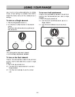
Page 49: ...5 3 OVEN LIGHT CR COOK TOP ELEMENT For Model LSE4613ST LSE4613BD LR RR COOK TOP ELEMENT ...

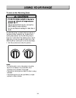
Page 50: ...5 4 RF COOK TOP ELEMENT LF COOK TOP ELEMENT For Model LSE4613ST LSE4613BD ...

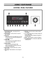
Page 51: ...5 5 WARM PROOF EASY CLEAN BROIL ...

Page 52: ... CONTROL Main PCB P N EBR80595606 SMPS PCB P N EBR80595701 Touch PCB P N EBR79627801 Encoder PCB P N EBR80327001 NFC PCB P N EBR78789101 Buzzer PCB P N EBR76332902 Relay PCB P N EBR80595407 Front Back Controller assembly ...

Page 53: ...6 2 COMPOSITION OF CONTROL Main PCB Main PCB P N EBR80595606 P N EBR80595407 Relay PCB Relay PCB CN40 CN03 CN22 CN50 CN51 CN01 CN20 CN53 CN31 CN52 CN51 CN53 CN52 ...

Page 54: ...6 3 COMPOSITION OF CONTROL SMPS PCB SMPS PCB Encoder PCB Encoder PCB CN02 CN01 CN41 P N EBR80595701 P N EBR80327001 ...

Page 55: ...6 4 COMPOSITION OF CONTROL T Touch PCB ouch PCB NFC and Buzzer PCB NFC and Buzzer PCB P N EBR79627801 P N EBR78789101 P N EBR76332902 ...

Page 56: ...e Off 2 Press the button in the following order _ _ Oven light Oven Light hold for 3 seconds 3 Press the OVEN LIGHT button again hold for 3seconds 4 Select the t0 by press the button 5 Press the START button 6 Start the test by press the START button again Model Option Software version Only software version is displayed at the right digits ...

Page 57: ... is displayed 7 Whenever you input the START button the relay operation sequence should be as seen below Relay Operation Sequence Conv Heater Broil Inner DLB C Fan High C Fan Low B Fan High B Fan Low RY11 RY12 RY13 RY8 RY9 RY1 RY2 Active Load Icon SW Version ...

Page 58: ... heater relays and DLB relay are open Symptom Oven hot F6 Check All heater relays are open shorted Symptom Oven lamp not operating Check the Lamp coil s resistance Symptom Door lock fail F10 Check relative part Symptom Sensor error or no heating F1 F2 Check Sensor resistance ...

Page 59: ...on and encoder is placed in the Off 2 Press the button in the following order _ Oven light Oven Light hold for 3 seconds If the oven has a malfunction the Oven will show the failure Code like FIG 1 If the oven do not has any failure the Oven will show it like FIG 2 NOTE After checking the F code press the CLEAR button to remove all codes 8 1 TROUBLESHOOTING FIG 1 FIG 2 Type of F Code Type of F Cod...

Page 60: ...is over 650 F continuously during 2 minutes on cooking except self cleaning EXCEPT PROOF and WARM Starting temperature of 130 For less and the oven door is closed the oven inside temperature does not go up more than 10 F compared with the starting temperature for 5minutes after the start of cooking In case of Door Lock Failure during operating Lock motor 1 Wiring 2 Oven Sensor 1 Wiring 2 Oven Sens...

Page 61: ...E Symptom Check Point 1 Power Failure Dead 2 No Display 1 Check Electrical Wiring 2 Check the SMPS PCB Input Voltage with CN01 Main PCB CN03 CN02 SMPS PCB CN01 Thermostat WH RD Pin No 1 3 4 7 6 7 Vf 4 3V 33V 12V Voltage CN01 CN02 CN03 ...

Page 62: ...econnect If defective harness replace or fix 1 No Yes Check the connection of Power Cord Normal Reconnect If defective harness replace or fix 2 3 Check the AC input of SMPS PCB SMPS PCB CN01 Pin 1 and 3 120V AC No Yes Go to 7 On the next Page 4 No Yes Check the connection of L1 and N at Terminal block Normal Reconnect 5 No Yes Check the Thermostat Normal Short Abnormal Open Normal Replace the Ther...

Page 63: ... connecting states between CN02 of SMPS PCB and CN03 of Main PCB Is it OK No Yes Replace the Main PCB 7 Reconnect If defective harness replace or fix If the same phenomenon occurs even though after fixed connection you should replace the Main PCB ...

Page 64: ...CHECKING FLOW CHART BY FAILURE E D F L1 L2 RY12 RY11 Broil Conv Heater RY13 C B A Symptom Check Point 1 No heating 2 F9 1 Check Electric Wiring 2 Check Heater s Resistance 3 Check the Sensor A B C D E F G H ...

Page 65: ...9 5 CHECKING FLOW CHART BY FAILURE Symptom Check Point 1 No heating 2 F9 1 Check Electrical Wiring 2 Check Heater s Resistance 3 Check the Sensor CN31 ...

Page 66: ...of Relay PCB All taps 2 Electric wiring of electric element Yes Reconnect If defective harness Replace or fix 1 Conv Heater Broil Unplug the unit Check the resistance of each heater Normal Measure the resistance after cooling down The resistance is shown below No Replace the failed heater 2 Broil yes No Conv Heater ...

Page 67: ...after replace Relay PCB you should replace the Main PCB Heater Resistance Ω Approximately Broil 13 5 Conv Heater 23 Is the value of thermistor normal Refer below Check with the test mode To enter the test mode follow these steps 1 Press the any button and encoder is placed in the Off 2 Press the button in the following order _ Oven light Oven Light hold for 3 seconds 3 Press the OVEN LIGHT button ...

Page 68: ...9 8 CHECKING FLOW CHART BY FAILURE Symptom Check Point 1 Door Lock System Failure 2 F10 1 Check the Electrical wiring 2 Check the Motor s Resistance 3 Check the Relay PCB Door Lock Relay CN31 ...

Page 69: ...9 9 CHECKING FLOW CHART BY FAILURE Symptom Check Point 1 Door Lock System Failure 2 F10 1 Check the Electrical wiring 2 Check the Motor s Resistance 3 Check the Relay PCB Door Lock Relay ...

Page 70: ...he following 1 Electric wiring of relay in Relay PCB 2 Electric wiring of Locking Motor and Micro Switch 3 Electric wiring of CN31 of Main PCB Yes Reconnect If defective harness replace or fix 2 Unplug the unit No No Note Just after self clean start the door lock motor starts to rotate During this time if the door lock switch does NOT operate properly after rotating twice then supervising circuit ...

Page 71: ...ce the Main PCB Is the door lock switch micro switch normal measure the resistance of door lock switch normally open type No Replace the micro switch 3 Yes Abnormal Normal Is the resistance of the lock motor normal measure the resistance of lock motor Normal approximately 2 6kΩ Abnormal infinite or below 5 Ω No Replace the lock motor 4 Yes ...

Page 72: ...9 12 CHECKING FLOW CHART BY FAILURE Symptom Check Point 1 Sensing Fail 2 F1 3 F2 1 Check the Electrical Wiring 2 Check the Test Mode 3 Check the Sensor s Resistance CN31 ...

Page 73: ...n 2 CN31 of Main PCB No Yes Yes Unplug the unit Sensing Fail F1 F2 Yes Reconnect or adjust the connection 1 Sensor connection CN31 Is the resistance of thermistor normal Check Pins 4 and 5 of CN31 wiring in main PCB Normal approximately 1 09kΩ at 25 C No Replace the defective Thermistor 2 CN13 ...

Page 74: ...utton and encoder is placed in the Off 2 Press the button in the following order _ Oven light Oven Light hold for 3 seconds 3 Press the OVEN LIGHT button again hold for 3seconds 4 Select the t3 by press the button 5 Press the START button Normal Thermistor value at room temp is from 70 F to 90 F Yes Replace the Relay PCB 3 4 Plug in the unit Replace the Main PCB No ...

Page 75: ...15 CHECKING FLOW CHART BY FAILURE E D F L1 L2 RY12 RY11 Broil Conv Heater RY13 C B A Symptom Check Point 1 Oven hot 2 F6 1 Check the Resistance of the Relay 2 Check the Sensor s Resistance A B C D E F G H ...

Page 76: ...9 16 CHECKING FLOW CHART BY FAILURE Symptom Check Point 1 Oven hot 2 F6 1 Check the Resistance of the Relay 2 Check the Sensor s Resistance CN31 ...

Page 77: ...Normal approximately 1 09kΩ at 25 C No Replace the defective Thermistor 1 CN31 Unplug the unit Yes Yes Yes Yes Is the heater relay normal Measure the resistance of Heater relay and Live Normal infinite Abnormal shorted No Replace the Relay PCB 2 Broil Heater Relay Conv Heater Relay Tab 02 and Tab 22 RY12 Tab 02 and Tab 21 RY11 ...

Page 78: ...elow Check with the test mode To enter the test mode follow these steps 1 Press the any button and encoder is placed in the Off 2 Press the button in the following order _ Oven light Oven Light hold for 3 seconds 3 Press the OVEN LIGHT button again hold for 3seconds 4 Select the t3 by press the button 5 Press the START button Normal Thermistor value at room temp is from 70 F to 90 F Yes Replace th...

Page 79: ...9 19 CHECKING FLOW CHART BY FAILURE Symptom Check Point 1 Key not working 2 F3 Error 1 Check the Door Locking System 2 Check the Electrical Wiring CN53 ...

Page 80: ...And then check button operation using key test mode o enter the test mode follow these steps 1 Press the any button and encoder is placed in the Off 2 Press the button in the following order _ Oven light Oven Light hold for 3 seconds 3 Press the OVEN LIGHT button again hold for 3seconds 4 Select the t7 by press the button 5 Press the START and Check the button Refer to the next page appendix 2 3 P...

Page 81: ...e normal operation will be the number that corresponds to the Key displayed on the VFD 2 If the key access order was changed the buzzer make double beep sound 3 The buzzer does NOT beep when a key was accessed it would be defected How to stop Key Test mode Press 1st Cook time 2nd 8th START Key operation T Key operation Test sequence est sequence 1st 8th First ...

Page 82: ...EXPLODED VIEW EV INTRODUCTION 9504 9501 9506 Customer Model Product Code SVC Model MODEL ...

Page 83: ... EV DOOR PARTS 1704 1382 1035 1015 W230 1703 1020 1008 102U W243 W222 W222 1000 102S 102L 173U W101 W101 1018 1009 1735 W230 ...

Page 84: ...OLLER PARTS 2002 2026 303R 2085 2084 2082 2084 2085 2082 2037 2050 260E 303L 2026 W280 2052 2052 2052 5206 260B 260M 2051 2221 244D 244D 244S 244E 2052 2042 2043 2044 2046 2041 2047 2090 2053 2385 2001 260K 2006 ...

Page 85: ... EV COOKTOP PARTS 3056 3215 3006 3016 330M 330H 3205 3022 3204 330S 330S 301C ...

Page 86: ...DRAWER PARTS 8523 8507 8501 8514 8517 8524 8602 8520 8512 5505 5505 8504 6008 8508 8513 1009 8708 8708 W230 EV ...

Page 87: ...535 5407 5406 5512 5513 5510 5506 5014 5039 3057 3013 3093 3024 5502 5063 5501 5504 5124 5405 5408 W232 5533 W124 W233 5521 W291 3222 5556 5019 3208 5535 W129 W102 5021 5532 5516 5511 5032 3501 5066 W229 8511 5509 5611 507R 5611 507S 5508 5016 5518 5006 EV ...

Page 88: ......

Reviews: