background image

Service

Digital Appliance

TRAINING MANUAL

ELECTRIC RANGE

LRE30451

LRE30755

Summary of Contents for LRE30451

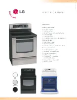
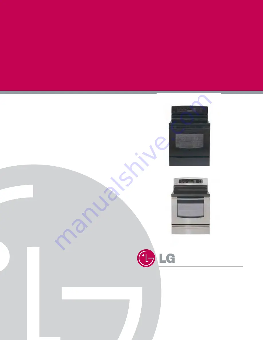
Page 1: ...Service Digital Appliance TRAINING MANUAL ELECTRIC RANGE LRE30451 LRE30755 ...

Page 2: ... you need repairs contact an LG Service Center or your dealer If the power cord is defective it must be replaced by a qualified service agent with a UL listed range cord Electrical leads and cables should not be allowed to touch the oven Rating plate is located on the left side of warming drawer The power supply of the appliance should be turned off when it is being repaired FORWARD LG Electronice...

Page 3: ... Bake Convection Roast Favorites Cook Warm Oven lockout Changing hour mode on clock 12HR 24HR Proof Self Clean Warming drawer COMPONENT ACCESS 3 1 3 17 Component Locations 3 1 Removing the Back Control cover and Key membrane Assembly 3 2 Removeing the Control Power Supply and Power Control Board PCB 3 3 Removing the Surface Element and the Ceramic Glass Cooktop 3 4 Removing the Door Latch and the ...

Page 4: ...OL 5 1 5 4 Main PCB 5 2 Cook top display PCB 5 3 Cook top relay PCB 5 4 Oven relay PCB 5 4 FAILURE MODE FLOW CHART 6 1 6 11 No display No power 6 1 6 4 Oven does not heat 6 5 6 7 Cook top does not heat 6 8 6 9 Oven lamp does not operate 6 10 No key input 6 11 FAILURE CODES 7 0 F CODE FLOW CHART 7 1 7 10 F 1 error 7 1 F 2 error 7 2 7 4 F 3 F 4 error 7 5 7 6 F 5 F 6 error 7 7 7 8 F 9 error 7 9 7 10 ...

Page 5: ...onotuseatowelor otherbulkycloth 1 1 GENERAL IMPOR IMPORT TANT SAFETY INSTRUCTIONS ANT SAFETY INSTRUCTIONS Read and follow all instructions before using your oven to prevent the risk of fire electric shock injury to person or damage when using the range This guide don t cover all possible conditions that may occur For further assistance contact your service agent or manufacturer This symbol will he...

Page 6: ...kind should be used in or around any part of the oven Clean in the self clean cycle only parts listed in this manual Before self cleaning the oven remove the broiler pan and any utensils from the oven Never keep pet birds in the kitchen the health of birds is extremely sensitive to the fumes released during an oven self clean cycle Fumes may be harmful or fatal to birds Move birds to well ventilat...

Page 7: ...ial Number label and Tech Sheet locations are shown below Model Serial Number Location MODEL SERIAL NUMBER LABEL MODEL SERIAL NUMBER LABEL AND TECH SHEET LOCA AND TECH SHEET LOCATIONS TIONS Tech Sheet Location On Low Rear Cover ...

Page 8: ......

Page 9: ......

Page 10: ...is not required when using broil All foods should be turned at least once except fish which does not need to be turned Convection Bake Roast Mode Upper element lower element Rear element some model and fan operate during convection bake Convection bake should be used for cooking casseroles and roasting meats Oven should be preheated for best results when using convection bake Pans do not need to b...

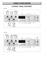
Page 11: ...j j j j LRE30451 LRE30755 ...

Page 12: ... ON OFF PAD Press to select the timer feature 10 COOK TIME PAD Press and then use the number pads to set the amount of time you want your food to cook The oven will shut off when the cooking time has run out 11 START TIME PAD Use along with BAKE CONV BAKE CONV ROAST COOK TIME and SELF CLEAN pads to set the oven to start and stop automatically at a time you set 12 COOK WARM PAD Press to keep cooked...

Page 13: ...ally turns ON when the door is opened The oven light may also be manually turned ON or OFF by pressing the OVEN LIGHT pad Note The oven light cannot be turned on if self clean feature is active 4 TIMER ON OFF To cancel timer at any time touch TIMER ON OFF pad Note 1 If you press TIMER ON OFF pad once this allows you to select seconds for example if you press 5 and 6 it means 56 seconds 2 If you pr...

Page 14: ...HOUR MODE ON CLOCK 12HR 24HR 14 PROOF 15 SELF CLEAN 2 4 USING YOUR RANGE CONV BAKE Desired Temp START CONV ROAST Desired Temp START START FAVORITES Once Bread Twice Meat 3 times Chicken START SELF CLEAN Once 3 hour Twice 2 hour 3 times 4 hour START COOK WARM Press and hold the START pad for 3 seconds to activate or reactivate LOCKOUT START PROOF Press and hold the START pad for 3 seconds Press 1 p...

Page 15: ...stic wrap to cover food Plastic may melt onto the drawer and be very difficult to clean Use only utensils and cookware recommended for oven use in the Warming Drawer To set the warming drawer control 1 Press the ON OFF pad at the WARMING DRAWER position The indicator light will flash If no further pads are pressed within 25 seconds the display will clear 2 Press once to turn on the power level for...

Page 16: ...low COMPONENT LOCA COMPONENT LOCATIONS TIONS Broil Heater Oven Sensor Door Switch Surface Elements Door Locking Motor Micro Switch Cook Top Relay PCB Main PCB Cook Top Display PCB Bake Heater Hinge Hanger Warming Drawer Heater Warming Drawer Sensor Oven Light LVT Convection Heater Door Latch Assembly Convection Motor Oven Relay PCB Thermal Fuse ...

Page 17: ...KEY Membrane assembly and separate PCB assembly REMOVING THE BACK CONTROL COVER REMOVING THE BACK CONTROL COVER AND KEY MEMBRANE ASSEMBL AND KEY MEMBRANE ASSEMBLY Y WARNING ELECTRICAL SHOCK HAZARD Disconnect power before servicing the range Replace all panels before operating range Failure to do so can result in death or electrical shock CAUTION When you work on the electric range be careful when ...

Page 18: ...proper pcb in default mode and check main pcb NOTE Refer to the page 5 1 5 4 for composition of control board 5 To remove the control power supply a Disconnect 2 connectors b Remove the two screws WARNING ELECTRICAL SHOCK HAZARD Disconnect power before servicing the range Replace all panels before operating range Failure to do so can result in death or electrical shock CAUTION When you work on the...

Page 19: ...ment and limiter terminals b Remove the element bracket screw shown above for the element you are servicing d Carefully lift the bottom of the bracket just far enough to remove the element REASSEMBLY NOTE When you reinstall the element make sure that the wires are inserted into the correct tap then reinstall the bracket screw to secure it to the cooktop 3 4 COMPONENT ACCESS REMOVING THE SURF REMOV...

Page 20: ...e two screws from the door latch and remove the latch b Remove the door latch from the burner box and unhook the actuating rod 5 To remove the door switch a If not already done raise the cooktop see page 3 4 for the procedure b Remove the door switch from the range To do this squeeze tabs and use a ratchet extension or a small socket and tap it out of the hole with a hammer c Disconnect the wires ...

Page 21: ...ly going to the range 2 Open the oven door and remove the racks from inside the oven 3 To remove the broil element a Remove the 4 screws from the front and rear brackets b Pull the element forward so that you can access the terminals and disconnect the wires CAUTION When you work on the electric range be careful when handling the sheet metal parts Sharp edges may be present and you can cut yoursel...

Page 22: ...e element Hidden bake element Hidden bake element Hidden bake element Hidden bake element Hidden bake element Hidden bake element Hidden bake element Hidden bake element Hidden bake element Hidden bake element Hidden bake element Hidden bake element Hidden bake element Hidden bake element Hidden bake element Hidden bake element Hidden bake element Hidden bake element Hidden bake element Hidden bak...

Page 23: ... clockwise Fan blade can be replaced from inside oven 8 To remove Fan motor assembly disconnect wire connection and remove the three bracket screws 9 Pull the fan motor assembly forward REMOVING THE CONVECTION ELEMENT REMOVING THE CONVECTION ELEMENT F FAN BLADE AND F AN BLADE AND FAN MOT AN MOTOR OR Fan cover Convection heater Nut Fan cover Screws 4ea Mounting Screws 3ea Cavity Inner Outer Fan bla...

Page 24: ...to remove the socket from the front of the oven you will have to push the socket out from the back of the unit 5 Disconnect the wires from the socket terminals CAUTION When you work on the electric range be careful when handling the sheet metal parts Sharp edges may be present and you can cut yourself if you are not careful CAUTION Be careful not to scratch or chip the oven liner paint when you re...

Page 25: ... lock assembly is located at the back side of range The structural elements are as below 1 When the oven control is programmed and started for the Self clean and Lock out mode PCB Power control board chip operates the motor 2 The cam moves the door hook connected to latch rod from unlocked position to locked position from locked Position to unlocked position 3 The cam activates the micro switch th...

Page 26: ... handling the sheet metal parts Sharp edges may be present and you can cut yourself if you are not careful Main oven Sensor connector Main oven Sensor connector Main oven Sensor connector Main oven Sensor connector Main oven Sensor connector Main oven Sensor connector Main oven Sensor connector Main oven Sensor connector Main oven Sensor connector Main oven Sensor connector Main oven Sensor connec...

Page 27: ... 2 rear bracket screws 2 rear bracket screws 2 rear bracket screws 2 rear bracket screws 2 rear bracket screws 2 rear bracket screws 2 rear bracket screws 2 rear bracket screws 2 rear bracket screws 2 rear bracket screws 2 rear bracket screws 2 rear bracket screws 2 rear bracket screws 2 rear bracket screws 2 rear bracket screws 2 rear bracket screws 2 rear bracket screws 2 rear bracket screws 2 r...

Page 28: ...Step 3 Fully open the door If the door will not fully open the indentation is not seated correctly in the bottom edge of the slot Step 4 Push the hinge locks up against the front frame of the oven cavity to the locked position Step 5 Close the oven door Toremove thedoor Step 1 Fully open the door Step 2 Pull the hinge locks down toward Fig 1 the door frame to the unlocked position Step 3 Firmly gr...

Page 29: ...for stainless model a Remove the 4 door handle screws and lift the door handle off door trim and slide up the door handle 6 To remove the door handle trim glass for white Black model a Remove the handle and glass trim screws b Lift the door handle off door trim c Slide up the door trim and pull the glass trim forward 4 top liner screws 4 top liner screws 4 top liner screws 4 top liner screws 4 top...

Page 30: ...e hanger screws Hinge hanger screws lnsulation cover lnsulation cover lnsulation cover lnsulation cover lnsulation cover lnsulation cover lnsulation cover lnsulation cover lnsulation cover lnsulation cover lnsulation cover lnsulation cover lnsulation cover lnsulation cover lnsulation cover lnsulation cover lnsulation cover lnsulation cover lnsulation cover lnsulation cover lnsulation cover lnsulat...

Page 31: ...re seated in their liner holes and that the ends of the gasket are pushed fully into their holes Use the pointed end of a pencil to push the gasket ends into the holes Door gasket Door gasket Door gasket Door gasket Door gasket Door gasket Door gasket Door gasket Door gasket Door gasket Door gasket Door gasket Door gasket Door gasket Door gasket Door gasket Door gasket Door gasket Door gasket Door...

Page 32: ...the left or right side panel 8 Pull the back of the side panel out from the range approximately 10 9 Push forward and remove the side panel 1 Turn off the electrical supply going to the range 2 Remove the oven door from the range see page 3 13 for the procedure 3 Pull the range away from the wall so you can access the back of the unit 4 Remove the 16 screws from the rear panel and remove the panel...

Page 33: ...connectors far enough 3 Resistance checks must be made with power cord unplugged from outlet and with wiring harness or connectors disconnected NOTE Below Ω value were tested at room temperature 77F 25 C Before testing any of components perform the following checks WARNING Disconnect power supply cord from the outlet before servicing Replace all panels and parts before operating Reconnect all grou...

Page 34: ...le meter scale R x 1000 1 Refer to page 3 3 for the servicing procedure 2 Measure the resistance Multiple meter scale R x 1000 Normal Approximately 27 Ω 10 If not replace Components Test procedures Results NO COM Normal Approximately 2 6 kΩ 10 If not replace Abnormal Infinite open below 5Ω shorted Door latch open Door latch Locked Continuity Infinite NOTE After checking for the continuity of switc...

Page 35: ...al Approximately 1 09 kΩ 10 If not replace Door open Door closed Continuity Infinite NOTE Oven sensor is so sensitive to temperature Do test after cooling down sufficiently 1 Refer to page 3 12 for the servicing procedure 2 Measure the resistance after cooling down Multiple meter scale R x 1000 Normal Approximately 4 6 kΩ 10 If not replace NOTE Oven sensor is so sensitive to temperature Do test af...

Page 36: ...tance after cooling down Multiple meter scale R x1 Normal Approximately 17 Ω 10 If not replace 1 Refer to page 3 12 for the servicing procedure 2 Measure the resistance after cooling down Multiple meter scale R x1 Normal Approximately 95 Ω 10 If not replace NOTE Ω Value was tested at room temperature 77F 25 C Be careful the element is sensitive to temperature NOTE Ω Value was tested at room temper...

Page 37: ...4 5 Oven lamp 1 Measure the resistance after cooling down Multiple meter scale R x1 Components Test procedures Results Normal Below 5 Ω If not replace ...

Page 38: ...test leads to limiter terminals 1A and 2A The meter should indicate continuity 0Ω 6 Touch the ohmmeter test leads to limiter terminals 1B and 2B With the temperature below 150 F the meter should indicate an open circuit infinite With the temperature above 150 F the meter should indicate continuity 0Ω Components Test procedures Results Normal Approximately 46 Ω If not replace Normal continuity belo...

Page 39: ...erminals 1A and 2A the meter should indicate continuity 0 Ω 6 Touch the ohmmeter test leads to limiter terminals 1B and 2B With the temperature below 150 F the meter should indicate an open circuit infinite With the temperature above 150 F the meter should indicate continuity 0 Ω Components Test procedures Results Normal Approximately 565 Ω If not replace Normal continuity below 0 5 Ω If not repla...

Page 40: ...meter should indicate continuity 0 Ω 6 Touch the ohmmeter test leads to limiter terminals 1B and 2B With the temperature below 150 F the meter should indicate an open circuit infinite With the temperature above 150 F the meter should indicate continuity 0 Ω 4 8 Dual surface element Right Front RF Components Test procedures Results Normal Approximately 32 Ω Normal Approximately 55 Ω Normal continui...

Page 41: ...t Back Back Controller assembly Main PCB P N 6871W1N009A Front Back Cook top display PCB P N 6871W1N010A Front Back Cook top relay PCB P N 6871W1N011A Front Back Oven relay PCB P N 6871W1N012A Front Back PCB case assembly Key pad assembly ...

Page 42: ... Warming drawer display control Cook top heater control Warmer zone RR LR RF LF Cook top display control Oven lamp door lock motor convection fan control Detecting oven temperature warming drawer temperature Buzzer sound control Key entry Door open close Door lock unlock detection Error mode detection and pop up Supervising hot cook top element P N 6871W1N009A COMPOSITION OF CONTROL ...

Page 43: ...ft Rear Left Front power level indication Dual radiant surface elements Right Front inner outer power level indication Dual radiant surface element size indication Right Front inner outer Single radiant surface elements warming zone Center Rear power level indication P N 6871W1N010A COMPOSITION OF CONTROL ...

Page 44: ...al Radiant Surface Elements Right Front INNER OUTER on off power level relay switching Single Radiant Surface Elements Warming Zone Center Rear on off power level relay switching Supervising cook top element hot Warm drawer power level 5 level indication P N 6871W1N011A Oven relay PCB Oven relay PCB Main function Oven heater on off relay switching DLB Broil Bake Warming drawer convection P N 6871W...

Page 45: ...y input Yes No Yes Some beep sound Cook top display blank Check AC input voltage of Main PCB Main PCB CN2 pin 1 and 3 Replace the cook top display PCB 010A 4 5V 5 5V END Replace the main PCB 009A END 1 CN14 Pin 10 and 12 The voltage should be 4 5V 5 5V Main PCB 009B No Yes No Check the thermal fuse See the page 3 1 Go to page 6 4 ...

Page 46: ...Yes No Yes Some beep sound Warming drawer display blank Check AC input voltage of Main PCB Main PCB CN2 pin 1 and 3 Replace the warming drawer display PCB 011A 4 5V 5 5V END Replace the main PCB 009A END 1 CN16 Pin11 Voltage should be 4 5V 5 5V Main PCB 009B No Yes CN9 Pin1 No Check the thermal fuse See the page 3 1 Go to page 6 4 ...

Page 47: ...splay Enter key input Yes No Yes Some beep sound Oven display blank Check AC input voltage of Main PCB Main PCB CN2 pin 1 and 3 Replace the main PCB 009A END 1 No display No power Go to page 6 4 No Check the thermal fuse See the page 3 1 ...

Page 48: ...defective harness 1 Check the power transformer Refer to the below measure LVT coil resistance Normal approximately Fig 1 Primary S3 S2 S1 P Secondary Fig 1 Side Lead Color DCR Ω P S1 S2 S3 black white yellow blue yellow green green red red 25 28 4 2 4 9 1 5 1 8 1 1 1 3 Replace the Main PCB 009A Normal END Replace the power transformer END No Yes ...

Page 49: ...over 5 minutes on preheating where door is closed except proof and cook warm During cook No Heating Main Oven Disconnect power Check for loose connections at bake broil convection heater terminal and harness Check the bake heater measure the resistance after cooling down Normal approximately 17Ω Normal END Continued on the next page No Yes Reconnect If defective harness replace or fix ...

Page 50: ...ter cooling down Normal approximately 14Ω Normal END No Yes Replace the bake heater Check the convection heater measure the resistance after cooling down Normal approximately 17Ω Normal END No Yes Replace the broil heater Normal END No Yes Replace the convection heater Continued on the next page ...

Page 51: ...heck the oven sensor measure the resistance after cooling down Normal approximately 1 09kΩ Normal END Reconnect No Yes Replace the oven relay PCB 012A Normal Replace the main PCB 009A Replace the oven sensor END END For further check of main PCB Refer to the appendix A No Yes Normal Yes ...

Page 52: ...g All or a part of cook top heaters Disconnect power Check for loose connection at board 011B PCB to cook top heaters Check for loose connector main PCB 009A CN9 and CN16 Normal END No Yes Reconnect If defective harness replace or fix Continued on the next page ...

Page 53: ...d pull the cook top relay PCB 011A forward from the PCB case Inspect the cook top relay PCB 011A Wide pattern Live part blown out pin to pin short or connector harness damaged Normal END No No Yes Repair and fix END Replace the Cook top relay PCB 011A END Replace the main PCB 009A Repairable by yourself Yes No Yes ...

Page 54: ...or fix END Replace the oven lamp END No No Yes Normal Normal END No Yes Yes END Reconnect Oven lamp does not operate Disconnect power Check for loose connection of oven lamp terminal and harness Check for loose connector main PCB CN1 Check the oven lamp measure the resistance Normal Below 5 Ω Abnormal infinite Abnormal Infinite ...

Page 55: ...put Key does not input Reconnect the main PCB connector CN11 and CN20 more than two times Normal Yes Some keys or All keys Normal END END All END Yes No No Some Replace the main PCB 009A Replace the main PCB END Replace the keypad assembly ...

Page 56: ...N if there is any problem Replace oven sensor E If you couldn t find any problem Replace Control PCB A Perform step 1 through 2 above B Open the back panel and check continuity of the sensor and Control PCB C Disconnect sensor from harness D Measure Ω value between connector pins Approximately 50kΩ at room temperature 77F 25 C Measure value between sensor chassis and any connector pins Ω value sho...

Page 57: ...rt for 60 seconds Key short error F 1 Plugged out the power remove keypad tail and check F 1 error recur or not after plugging in the power Remove the main PCB 009A harness and pull the PCB 009A forward from the PCB case Replace keypad or keypad assembly Disconnect power recur Yes Front Back Normal Repairable by yourself END Yes Yes No No No END Replace the main PCB 009A Repair and fix END ...

Page 58: ...itch does not operate properly after rotating twice then supervising circuit detects a Door Lock failure and the F 2 error code appears Reconnect Normal END No Yes Door lock failed Disconnect power Check for loose connection on the micro switch and the door locking motor Check the oven door lock switch micro switch measure the resistance Normally open type NO COM Door latch open Door latch Locked ...

Page 59: ...nect Check the door locking motor measure the resistance normal approximately 2 6kΩ abnormal infinite or below 5 Ω Remove the main PCB 009A harness and pull the PCB 009A forward from the PCB case Check for loose connector Front main PCB CN4 Front CN4 CN4 CN4 CN4 CN4 CN4 CN4 CN4 CN4 CN4 CN4 CN4 CN4 CN4 CN4 CN4 CN4 CN4 CN4 CN4 CN4 CN4 CN4 CN4 CN4 CN4 CN4 CN4 CN4 CN4 3 2 1 ...

Page 60: ...4 F CODE FLOW CHART Door lock system error F 2 error Inspect connector pin solder of CN4 Back main PCB CN4 Back If pin solder is cracked repair and re use CN4 Cracked Replace END Repair and fix END No Yes ...

Page 61: ...s short for over 1 min after cook starts During cook During cook Main oven sensing failed Disconnect power Main oven sensing error F 3 F 4 error Check for loose oven sensor connector Check the main oven sensor measure the resistance after cooling down Normal approximately 1 09kΩ Normal END Reconnect No Yes Normal Replace the main oven sensor END No Yes Continued on the next page ...

Page 62: ...forward from the PCB case Yes Check for loose connector Front main PCB CN6 CN6 Normal No Yes END Reconnect and replace the bad harness Inspect connector pin solder of CN6 Back main PCB CN6 Back If pin solder is cracked repair and re use Cracked Replace END Repair and fix END No Yes CN6 CN6 CN6 CN6 CN6 CN6 CN6 CN6 CN6 CN6 CN6 CN6 CN6 CN6 CN6 CN6 CN6 CN6 CN6 CN6 CN6 CN6 CN6 CN6 CN6 CN6 CN6 CN6 CN6 C...

Page 63: ...in after warm drawer operates During operate During operate Warming drawer sensing failed Disconnect power Warming drawer sensing error F 5 F 6 error Check for loose warming drawer sensor connector Check the warming drawer sensor measure the resistance after cooling down Normal approximately 4 6kΩ Normal END Reconnect No Yes Normal Replace the warming drawer sensor END No Yes Continued on the next...

Page 64: ...Front main PCB CN5 CN5 CN5 CN5 CN5 CN5 CN5 CN5 CN5 CN5 CN5 CN5 CN5 CN5 CN5 CN5 CN5 CN5 CN5 CN5 CN5 CN5 CN5 CN5 CN5 CN5 CN5 CN5 CN5 CN5 CN5 Normal No Yes END Reconnect and replace the bad harness Inspect connector pin solder of CN5 Back main PCB CN5 Back If pin solder is cracked repair and re use Cracked Replace END Repair and fix END No Yes CN5 CN5 CN5 CN5 CN5 CN5 CN5 CN5 CN5 CN5 CN5 CN5 CN5 CN5 C...

Page 65: ...ing During cook Not self clean mode Oven is too hot F 9 Disconnect power Remove the oven relay PCB 012A harness and pull the oven relay PCB 012A forward from case Oven too hot error F 9 error Check for a welded bake relay measure the resistance Normal No END Replace the oven relay PCB Welded Normal Continuity Infinite Continued on the next page ...

Page 66: ...OW CHART Oven too hot error F 9 error Normal No END END Replace the oven relay PCB 012A Replace the main relay PCB 009A Yes Yes Check for a welded broil relay measure the resistance Welded Normal Continuity Infinite ...

Page 67: ...8 1 APPENDIX A SCHEMATIC DIAGRAM OF PCB ...

Page 68: ...B Refer to the page 6 1 6 4 Verify power is present at unit Verify that the circuit breaker is not tripped Replace household fuse capacity Check circuit breaker Repair or replace wiring see wiring diagrams Test and or replace element Test and or replace PCB Refer to the page 6 5 6 7 Verify all connections are clean and tight replace broken wires Test and or replace cook top PCB Refer to the page 6...

Page 69: ... down period after self clean cycle not complete Improper use of oven e g being used to heat the home Worn or broken broil stop roller Replace power control board PCB Replace power control board PCB Verify power is present at unit Verify that the circuit breaker is not tripped Replace household fuse but do not fuse capacity Refer to Owner s manual instructions Verity all connections are clean and ...

Page 70: ... controlled Oven sensor needs to be adjusted Adjust hinges or replace hinges Adjust or replace hinges Adjust hinges outward Do not cover racks with foil Install tempered glass toward the heat Do not use harsh abrasives or scouring pads See Owner s manual intructions Apply a small amount of vegetable oil to a paper towel and wipe the edges of the oven racks with the paper towel Do not spray with pa...

Page 71: ...door open and elements off RADIANT COOK TOP Wattage RR 1200W LR 1200W LF 2500W RF Right Front 1700W inner 2700W Dual CR 100W WIRE COLORS SYMBOL COLOR WH WHITE BK BLACK RD RED YL YELLOW PK PINK BL BLUE BN BROWN GN GREEN GY GRAY WARNING POWER MUST BE DISCONNECTED BEFORE SERVICING THE APPLIANCE SCHEMATIC DIAGRAM ...

Page 72: ...before checking electric oven circuit 1 Check the line voltage household fuse or circuit breaker 2 Check for loose wiring or mis wiring within electric range NOTE The following individual circuits are for use in diagnosis and are shown in the ON position BAKE COOK WARM PROOF BROIL OVEN LIGHT ...

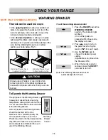
Page 73: ...10 3 WARMNING DRAWER SELF CLEANING For Model LRE30755SW SB ST ...

Page 74: ...10 4 CLOCK DISPLAY ON CR Warming Zone CONV BAKE CONV ROAST For Model LRE30755SW SB ST ...

Page 75: ...10 5 For Model LRE30755SW SB ST RR Cook top Element LR Cook top Element LF Cook top Element RF Cook top Element ...

Page 76: ...11 1 EXPLODED VIEW EV INTRODUCTION I DOOR PARTS DRAWER PARTS COOKTOP PARTS CONTROLLER PARTS CAVITY PARTS For Model LRE30451 LRE30755 ...

Page 77: ...11 2 EV INTRODUCTION II For Model LRE30455 LRE30755 DOOR PARTS DRAWER PARTS COOKTOP PARTS CONTROLLER PARTS CAVITY PARTS ...

Page 78: ...WTP028 WTT025 WTT025 WTT025 WTT025 WTT025 WTT021 WTT021 WTT034 WTT034 162082 13806D 149802 162081 14810Q 148901 WTP028 13213A 149801 162082 14775A 14775A 149804 149804 162083 148902 13550C 149803 13650A 14810D 13581A For Model LRE30455 LRE30755 ...

Page 79: ... II 13650A 149801 14775A 14775A 162083 162081 14810Q 13213A 148901 13551P 13806D 162082 14810D 162082 149801 WTT034 WTT034 WTT025 WSZ002 WSZ222 WSZ218 WTT025 WTT025 WTT025 13550C 13581A For Model LRE30455 LRE30755 EV ...

Page 80: ...11 5 CONTROLLER PARTS 23572A 249302 26170G 24790A 249301 268711 249303 268712 WTP013 WTP013 WTP013 33920P WTT021 WTT021 249802 249801 34930W 268713 23808A 24781M 23551E EV For Model LRE30455 LRE30755 ...

Page 81: ...1 6 COOKTOP PARTS 33301A 335302 335301 335303 335304 335303 33920P 349801 349801 33920P 349802 34790A WTT030 WTT024 WTT024 WTT018 WTT018 WSZ003 34970A 34970A 368771 368772 EV For Model LRE30455 LRE30755 ...

Page 82: ...70C 84818D 848101 84960D 83302D 834461 83550W 847781 83302D 848102 85300D WSZ225 84980D 83720D 83212D 84870B 84818S 84818S 84980D WTT052 WTT024 WTT052 WTT034 WTT034 WTT024 WTT025 13650A WTT030 WTT030 549803 549803 84870E 868771 84810D EV For Model LRE30755SW SB ST ...

Page 83: ...11A 55012A 55900C 53720A 55231C 55233A 353002 548101 539202 56913A 539202 466001 54810H 34930W 53720B 353001 36549C 568711 549801 548102 56549A 549802 54270A 36640B 35012A 56322A 548102 33550H WNH201 353003 539201 549803 54810H 568771 33808A 33808B 53504A 333901 333902 350261 350262 350263 350264 SPEC 120V 40W 568772 56630T EV For Model LRE30755SW SB ST ...

Page 84: ...RTS WTP013 WTP013 85012D 834462 84870C 84818D 83302D 834461 83550W 847781 83302D WTP028 83720D 83212D 84870B 84818S 84818S WTT024 WTT024 WTT025 WTT030 WTT030 549803 549803 84870E 84810D EV For Model LRE30451SW SB ST ...

Page 85: ...037 54620A 33808A 54811A 55012A 55900C 33808B 53720A 55231C 55233A 353002 548101 539202 549803 56913A 539202 466001 54810H 34930W 53720B 353001 36549C 568711 549801 548102 56549A 549802 54270A 36640B 35012A 56322A 33550H 539201 54810H 53504A 568771 333901 350262 333902 350261 56630T SPEC 120V 40W WNH201 568772 EV For Model LRE30451SW SB ST ...

Page 86: ...C 268711 6871W1N002A PWB PCB ASSEMBLY SUB MAIN PCB DEF 268711 6871W1N009A PWB PCB ASSEMBLY SUB MAIN PCB DEF 268712 6871W1N010A PWB PCB ASSEMBLY SUB CKT DISPLAY PCB ABC 268712 6871W1N010B PWB PCB ASSEMBLY SUB CKT DISPLAY PCB DEF 268713 6871W1N011A PWB PCB ASSEMBLY SUB CKT RELAY PCB ABCDEF 333901 3390W0N002C TRAY METAL RECT ENAMEL SEA BL W326 5 L426 9 T1 0 ABCDEF 333902 3390W0N001C TRAY METAL RECT E...

Page 87: ...3828W5A8538 MANUAL OWNERS DEF 02 3828W5S6293 MANUAL SERVICE ABC 02 3828W5S6294 MANUAL SERVICE ABCDEF 04 3828W5U0512 MANUAL INSTALLATION ABCDEF 06 4922W5N001C TEMPLATE ANTI TIP DEF 07 3840W5T149A CARD TECHNICAL ABC 07 3840W5T149B CARD TECHNICAL ABCDEF 10 3890W2Y324A BOX YELLOW ABCDEF 13213A 3213W0N001C DOOR FRAME ASSEMBLY ENAMEL ABCDEF 13550C 3550W0N006A COVER INNER T0 5 DOOR BE 13551P 3551W0N002A ...

Page 88: ...CKET HINGE CAVITY FRONT PLATE ABCDEF 54811A 4811W0N002A BRACKET ASSEMBLY MAIN LATCH ABCDEF 55012A 5012W0N002A INSULATOR T0 8 NA WOOL COVER UPPER ABCDEF 55231C 5230W1N001A FILTER MECH CHARCOAL W45 L44 T5 0 ABCDEF 55233A 5233W0N001B VENT ASSEMBLY MESH TYPE ABCDEF 55900C 5900W1N001A FAN DIA 150 CCW 9 WING AIR FLOW ABCDEF 56322A 6322B62214A THERMISTOR PTC 03 07MX EXPAN 0C 1000OHM ABCDEF 56549A 6549W1S...

Page 89: ...ELAY 250VAC 16A 12VDC 1A VENTING ABCDEF WAT001 1ATF0502610 SCREW TAP TITE B TRUSS HEAD D5 0 L10 0 ABCDEF WNH002 1NHA0400018 NUT HEXAGON 1 D4 0 ABCDEF WNH201 1NHB0500032 NUT HEXAGON 2 D5 0 CDEF WNZ022 1NZZW1N002A NUT DRAWING BRASS DIA5 0 ABCDEF WSZ002 1SBF0402418 SCREW TAP TITE S BINDING HEAD D4 0 L8 0 ABCDEF WSZ003 1SBF0402618 SCREW TAP TITE B TRUSS HEAD D4 0 L10 0 ABCDEF WSZ218 1SZZW5N001B SCREW ...

Page 90: ......

Page 91: ......

Page 92: ......

Reviews: