LG LP1415GXR, Service Manual
Get the ultimate cooling solution with the LG LP1415GXR portable air conditioner. Stay comfortable year-round by downloading the free Owner's Manual from manualshive.com. This comprehensive manual provides step-by-step instructions for effortless installation and operation, ensuring maximum efficiency and comfort in any space. Don't miss out on this essential manual - download it today!
Share
Download

Reviews:
No comments
Related manuals for LP1415GXR

DPA060CB4WDB
Brand: Danby Pages: 40

OAPC187
Brand: Omega Altise Pages: 16
LP0813WNR
Brand: LG Pages: 48
LP1013WNR
Brand: LG Pages: 26
LP1015WNR
Brand: LG Pages: 26
LP1415GXR
Brand: LG Pages: 32
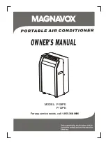
P-08PE
Brand: Magnavox Pages: 18
Premiere DPA110CB5BP
Brand: Danby Pages: 40

OAPC147
Brand: Omega Altise Pages: 15
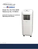
SG-PAC-08E4
Brand: Soleus Air Pages: 16
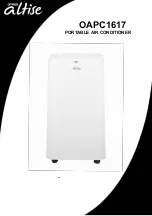
OAPC1617
Brand: Omega Altise Pages: 16
IPA2-1244-C
Brand: Impecca Pages: 9
PC26-AMEII
Brand: trentios Pages: 8
PC30-AM1BII
Brand: trentios Pages: 8
SRCOOL18K
Brand: Tripp Lite Pages: 40
ARP-7120
Brand: Royal Sovereign Pages: 36
PAC1402W
Brand: Koldfront Pages: 26
CLIMATEMASTER P-14000HCJ
Brand: Koolbreeze Pages: 12


