LG LP070CED-Y8, Manual
The LG LP070CED-Y8 is an exceptional product designed for optimal performance. Enhance your user experience with the (Spanish) Manual Del Usuario, which provides comprehensive instructions to maximize your device's potential. Download this essential manual for free from our website, ensuring seamless operation and convenience.
Share
Download


Reviews:
No comments
Related manuals for LP070CED-Y8

CTXG09QVJUW
Brand: Daikin Pages: 254
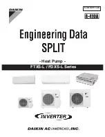
SUPER MULTI NX FDXS09LVJU
Brand: Daikin Pages: 206

MFZ-KJ25VE
Brand: Mitsubishi Electric Pages: 12
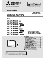
MFZ-KJ25VE
Brand: Mitsubishi Electric Pages: 40
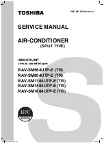
RAV-SM1104UTP-E (TR)
Brand: Toshiba Pages: 108
RAV-SM1104UTP-E (TR)
Brand: Toshiba Pages: 56
LW1214HR
Brand: LG Pages: 48
PCFY-P VGM-E
Brand: Mitsubishi Electric Pages: 200
PCFY-P VGM-E
Brand: Mitsubishi Electric Pages: 68
PEA-RP200 GA
Brand: Mitsubishi Electric Pages: 16
PEA-RP200 GA
Brand: Mitsubishi Electric Pages: 184
PEA-RP400 GA
Brand: Mitsubishi Electric Pages: 22
PKA-RP HAL
Brand: Mitsubishi Electric Pages: 108
PKA-RP HAL
Brand: Mitsubishi Electric Pages: 224
RAV-SM404MUT-E
Brand: Toshiba Pages: 288
RAV-SM404MUT-E
Brand: Toshiba Pages: 121
RAV-SM404MUT-E
Brand: Toshiba Pages: 16
RBC-AX32U(W)-E
Brand: Toshiba Pages: 1


