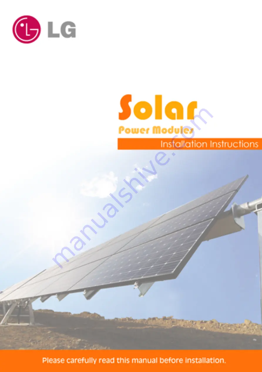
LG LG M1C Series, Installation Instructions Manual
The LG M1C Series provides outstanding performance and sleek design. For easy installation, follow the step-by-step instructions outlined in the detailed Installation Instructions Manual. This indispensable manual can be downloaded for free from manualshive.com, ensuring a seamless setup experience. Get your LG M1C Series manual today!
Share
Download


Reviews:
No comments
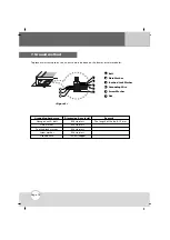
Related manuals for LG M1C Series

CS Series
Brand: TCSM Pages: 24

SL Series
Brand: Q CELLS Pages: 16

SP10
Brand: Campbell Pages: 14

SolarMax 600
Brand: ubbink Pages: 56

SFE Series
Brand: NDS Pages: 16

VBHNxxxSJ25 series
Brand: Panasonic Pages: 13

HIT Power 240S Series
Brand: Panasonic Pages: 12

MSX10
Brand: Campbell Pages: 13

Ingersoll Rand NAD 100W
Brand: Thermo King Pages: 22

Q.PEAK DUO XL-G11.2 Series
Brand: Q CELLS Pages: 12

Enecom HF135-6-16
Brand: En-Eco Pages: 20

Solar Charging Panel-D
Brand: Ezviz Pages: 3

eArc SMF175M-12
Brand: Sunman Pages: 4

VE1ZZPV W Series
Brand: GRUPPOSTG Pages: 23

ThermoLite 401414
Brand: Thermo King Pages: 15

XTREMESOLAR XTR-F300P
Brand: SFC Energy Pages: 22

Unisun M 10.12M
Brand: Unitek Pages: 58

TSP-120F
Brand: Togo POWER Pages: 8


