LG LAEC015-GN, Owner'S Manual
The LG LAEC015-GN Owner's Manual is available for free download on our website. This comprehensive manual provides detailed instructions and important information on operating and maintaining your LG LAEC015-GN product. Visit manualshive.com and get your manual now to unleash the full potential of your device.
Share
Download


Reviews:
No comments
Related manuals for LAEC015-GN
SLATE Series
Brand: Qeedji Pages: 52
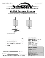
C-100
Brand: VASTEX Pages: 7
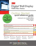
Digital Walldisplay 9000PD Plus
Brand: 3M Pages: 12
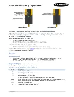
EZ-SCREEN LS
Brand: Banner Pages: 4
IDEA Screen
Brand: Da-Lite Pages: 2
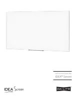
IDEA Screen
Brand: Da-Lite Pages: 8

ADVANTAGE DELUXE ELECTROL
Brand: Da-Lite Pages: 2

EXECUTIVE ELECTROL
Brand: Da-Lite Pages: 2

ADVANTAGE DELUXE ELECTROL
Brand: Da-Lite Pages: 2

TENSIONED EXECUTIVE ELECTROL
Brand: Da-Lite Pages: 2
Picture King
Brand: Da-Lite Pages: 16

ADVANTAGE ELECTROL
Brand: Da-Lite Pages: 2

ER Series
Brand: Neher Pages: 12
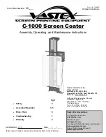
C-1000
Brand: VASTEX Pages: 8
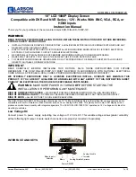
SCR-10IN-LCD-1080P-12V
Brand: Larson Electronics Pages: 2

VISAGE 770 SCREEN SYSTEM
Brand: Glasdon Pages: 4
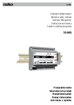
10-845
Brand: Niko Pages: 72
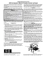
Ambassador 220V
Brand: Draper Pages: 2


