background image

CHASSIS : MV-031A

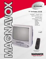
MODEL : KE/KL-20/21P32X 

MODEL : 

KF-20/21P32

MODEL  

CONTENT

SPECIFICATION ................................................1-2

SAFETY INSTRUCTIONS ............................ 1-3

SERVICING PRECAUTIONS ....................... 1-4

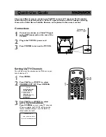
DESCRIPTION OF CONTROLS .................. 1-6

SECTION 1 

SUMMARY

TVCR

SERVICE MANUAL

Summary of Contents for KE-20P32X

Page 1: ...HASSIS MV 031A MODEL KE KL 20 21P32X MODEL KF 20 21P32 MODEL CONTENT SPECIFICATION 1 2 SAFETY INSTRUCTIONS 1 3 SERVICING PRECAUTIONS 1 4 DESCRIPTION OF CONTROLS 1 6 SECTION 1 SUMMARY TVCR SERVICE MANUAL ...

Page 2: ...ption Stand by 12W Channel Capability VHF 2 12 UHF 21 69 CATV S1 S20 HYPER S21 S41 Tuning System FVS 100 Program Or 200 Program Antenna UHF VHF 75 ohm Sound Output 3Wmax at 50KHz deviation Operating Environment Temp 0 40deg Humidity 85 ABBREVIA TIONS Used in this book ADJ Adjustment or Adjust AFC Automatic Frequency Control AGC Automatic Gain Control AMP Amplifier CPT Color Picture Tube DEF Deflec...

Page 3: ...perform an AC leakage current check on the exposed metallic parts of the cabinet such as antennas terminals etc to be sure the set is safe to operate without damage of electrical shock Leakage Current Cold Check Antenna Cold Check With the instrument AC plug removed from AC source connect an electrical jumper across the two AC plug prongs Place the AC switch in the on positioin connect one lead of...

Page 4: ...es are integrated circuits and some fieldeffect transistors and semicounductor chip components The following techniques should be used to help reduce the incidence of component damage caused by static by static electricity 1 Immediately before handling any semiconductor component or semiconductor equipped assembly drain off any electostatic charge on your body by touching a known earth ground Alte...

Page 5: ...the corresponding lead on the circuit board 4 Securely crimp each connection and solder it 5 Inspect on the circuit board copper side the solder joints of the two original leads If they are not shiny reheat them and if necessary apply additional solder Fuse and Conventional Resistor Removal Replacement 1 Clip each fuse or resistor lead at top of the circuit board hollow stake 2 Securely crimp the ...

Page 6: ...REWIND REVIEW rewinds the tape at high speed in the stop mode reviews fast the tape during playback 9 PLAY or PLAY X2 plays back the tape at normal or double speed 10 PAUSE STILL stops the tape temporarily during recording displays a still picture during playback 11 STOP stops the tape during playback or recording 12 SLEEP sets the sleep timer 13 TRK AUTO adjust the picture automatically or manual...

Page 7: ...t is powered by two AA type batteries Gently pull down the cover of the remote control handset until the battery compartment is exposed Install two batteries as indicated by the polarity symbols and marked inside the compartment Note To avoid damage from possible battery leakage remove the batteries if you do not plan to use the remote control handset for an extended period of time OK PR VOL PR VO...

Page 8: ...ws fast the tape during playback 16 FF FAST FORWARD CUE winds the tape forward at high speed in the stop mode fast forward playback 17 STOP EJECT stops the tape during playback or recording or ejects the tape 18 OK option accepts your selection or displays the current mode 19 TAPE IN INDICATOR option illuminates green while a video cassette tape is inserted 20 HEADPHONE SOCKET option connect the h...

Page 9: ...CHASSIS MV 031A MODEL KE KL 20 21P32X MODEL KF 20 21P32 MODEL CONTENT EXPLODED VIEW 2 2 EXPLODED VIEW PARTS LIST 2 3 DISASSEMBLY INSTRUCTIONS 2 4 SECTION 2 DISASSEMBLY PART TVCR SERVICE MANUAL ...

Page 10: ...2 2 EXPLODED VIEW 330 320 315 603 610 601 602 A00 501 520 174 913 510 112 153 170 150 310 943 400 120 ...

Page 11: ...ACKET MAIN HIPS 407AF BRACKET SMPS 520 6871VDM893D 6871VDM893E PWB ASSY MAIN2 WITH CPT PCB LOCA NO 510 6871VDM893N KIOTA 6871VDM893Z LGEAP PWB ASSY MAIN2 WITH CPT PCB LOCA NO 510 601 4810V00195E 4810V00195E BRACKET MAIN 15 21TVCR 35DECK MV031A HIPS 60HR 4810V00206B KIOTA 4810V00206A LGEAP BRACKET MAIN 4810V00206B LGERU BRACKET MAIN 602 4814V00158B 4814V00158B SHIELD BOTTOM P10 20 30 NON SBHG 603 4...

Page 12: ... CPT REMOV AL 1 After removal of VCR chassis and speaker assy remove the CPT board from CPT neck 2 Plase the cabinet with the front down on suitable cushion 3 Remove 4 screws swcuring the CPT to the cabinet 4 Carefully separate CPT from front cabinet PICTURE TUBE HANDLING CAUTION Due to high vacuum and large surface area of picture tube great care is needed when handling the picture tube Always li...

Page 13: ...21P32 MODEL CONTENT PURITY CONVERGENCE ADJUSTMENT 3 2 ADJUSTMENT INSTRUCTIONS 3 5 BLOCK DIAGRAM 3 9 WIRING DIAGRAM 3 10 TROUBLESHOOTING CHARTS 3 11 PRINTED CIRCUIT BOARDS 3 16 COMPONENT LOCATION GUIDE 3 17 SECTION 3 ELECTRICAL PART TVCR SERVICE MANUAL ...

Page 14: ...mpletely forward 5 Reconnect the internal degaussing coil 6 Position the beam bender locking rings at the 9 o clock position and the other three pairs of tabs 2 4 and 6 pole magnets at the 12 o clock position 7 Perform the following steps in the order given to prepare the receiver for the purity adjustment procedure a Face the receiver in the magnetic north direction b Externally degauss the recei...

Page 15: ...nal degaussing coil 9 Turn on the receiver connect a signal generator to the VHF antenna terminal and apply a crosshatch signal Caution During the convergence adjustment procedure be very careful not to disturb the purity adjustment tabs are accidentally move purity should be confirmed before proceeding with the convergence adjustments Note Make sure the focus is set correctly on this instrument b...

Page 16: ... and blue horizontal lines Fig upper right 17 Temporarily place a rubber wedge at the 5 o clock and 7 o clock positions to hold the horizontal position of the yoke 18 Check the 3 o clock and 9 o clock areas to confirm that the red and blue vertical lines are converged If the lines are not converged slightly offset the horizontal tilt of the yoke move the temporary rubber wedges if necessary to equ...

Page 17: ...IRCLE PATTERN depend on itmes 3 DECK LINE ADJ VCR DECK CIRCUIT ADJ 3 1 P2 P3 TEMPORARY ADJUSTMENT 3 1 1 NECESSARY INSTRUMENT 1 PAL SP Normal TAPE 2 OSCILLOSCOPE 3 10 1 PROBE 2 PIECES 4 SPECIAL NUT DRIVER P2 P3 for Adjustment 3 1 2 ADJUSTMENT 1 Play the PAL SP NORMAL TAPE 2 Connect the oscilloscope CH 1 to J123 H SW of main PCB 3 Connect the oscilloscope CH 2 to J158 RF of main PCB 4 With observing...

Page 18: ... the scope waveform 2 Check that if waveform satisfies with the linearity by pressing TRK Up and Down button 3 Tighten the X distant adjust screw 3 3 4 P2 P3 RF LINEARITY CHECK ADJUSTMENT 1 Adjust p2 p3 so that the the RF envelope waveform of the oscilloscope becomes C in figure 2 2 Check if the envelope waveform becomes maximum by pressing TRK Up Down button onestep 3 4 PG ADJUSTMENT Adjust it af...

Page 19: ...VC and adjust the RG and BG varying the VOL in the status of the initial data 32 of the CG in SVC MENU on the screen This chassis adjusts only the high light 4 6 DEFLECTION DATA ADJUSTMENT 4 6 1 Input PAL DIGITAL PATTERN EU05CH 4 6 2 Press SVC key on the service remote controller and select LINE SERVICE 2 mode Adjustable item is selected by CH key variable item is selected by VOL key 4 6 3 Deflect...

Page 20: ... PEAK CDL 2nd SIF RF Gain Green Drive Gain Red Drive Gain Blue Drive Gain Peaking Control Cathode Drive Level 2nd SIF 15 32 32 32 25 10 0 15 32 32 32 25 08 0 15 32 32 32 25 12 0 15 32 32 32 25 12 0 Ccntents 15 21 20 14 Mode 0 1 2 OFF BG DK INternal BPF BG EXTERNAL DK I INTERNAL BPF DK EXTERNAL BG I INTERNAL BPF Funtion Remark Note No 1 2 3 4 FRANCE GERMANY Other EU Except EU FRENCH GERMAN ENGLISH ...

Page 21: ...3 9 BLOCK DIAGRAM ...

Page 22: ...3 10 WIRING DIAGRAM TOUCH P805 P805 1 P708 1 P602 P804 P03 P01 P02 P708 P602 P805 P804 P708 P102 P702 P703 P901A SMPS PWB P802 P103 P100 CPT PWB ...

Page 23: ...in 9 of T801 YES NO POWER NO STAND BY Replace the Fuse Check the 6V Line of MAIN 1 BOARD Check if the Fuse is O K YES NO Check Replace DB801 R801 C806 NO Check Replace D806 Q801 R807 ZD801 C814 IC801 NO Check Replace FR851 D852 C856 Q860 Q861 Q862 ZD860 ZD861 R874 Check the pin 11 of P804 LOW NO Check Replace IC857 D856 F852 C875 NO TROUBLE SHOOTING ...

Page 24: ...n 9 of P804 YES NO POWER NO MONITOR ON Go to NO POWER NO ST BY BLOCK Go to NO RASTER BLOCK Check T701 Q781 and go to NO RASTER BLOCK Check the NO POWER NO ST BY BLOCK YES NO Check the pin 10 of P804 HIGH NO Check Replace D851 L851 C860 IC851 Check the pin 10 of P804 HIGH NO ...

Page 25: ...s there about 8V at pin 6 of P805 YES NO RASTER Go to NO POWER BLOCK Go to NO PICTURE BLOCK Is there about 115V at pin 3 of T701 YES NO Check Replace F852 D850 R858 IC853 C863 Check the 8V LINE of VCD BOARD NO Check the H OUT LINE of VCD BOARD Check Replace IC501 of VCD BOARD NO Check Replace Q782 T781 R783 Q781 NO Check Replace T701 5PIN CONNECTOR FR901 FR902 NO ...

Page 26: ... IC701 Does the V A V B signal appear at pin 4 7 of P805 YES NO Check Replace FR702 D703 C703 Check Replace FR701 D702 C704 NO Is there about 185V at pin 1 of P902 YES NO PICTURE Check the CVBS line of VCD Check Replace IC901 Check screen voltage Does the RGB signal appear at pin 3 5 7 of P901A YES NO Check Replace D701 C701 T701 5PIN CONNECTOR NO NO ...

Page 27: ...appear at pin 9 of P805 YES NO SOUND Check Replace FR854 D855 IC601 Check Replace speaker speaker connector Is there about 25V at pin 5 of IC601 YES NO Check the Audio source line of VCD Check the voltage at collector of Q602 Check Replace IC601 external components of IC601 NO NO ...

Page 28: ...3 16 PRINTED CIRCUIT BOARD MAIN ...

Page 29: ... J236 G5 J237 D1 J238 A4 J239 A5 J240 F2 J241 F4 J242 E2 J243 E2 J246 F3 J247 E5 J248 F4 J249 F4 J250 G4 J251 G4 J252 F4 J253 G3 J254 E4 J255 G5 J256 F5 J257 E2 J258 F4 J259 D5 J260 E4 J261 E4 J262 G5 J263 G4 J264 G4 J265 F5 J266 G5 J267 G4 J268 E2 J269 F5 J270 F4 J271 G2 J272 C4 J274 G3 J275 F2 J276 F3 J277 E5 J278 E5 J279 C5 J280 C2 J281 C2 J282 C3 J283 C5 J284 D5 J285 D5 J286 C5 J287 C3 J288 D4...

Page 30: ...3 18 POWER ...

Page 31: ...3 19 CPT AV 14 AV 20 ...

Page 32: ...1P32X MODEL KF 20 21P32 MODEL CONTENT Deck Mechanism Disassembly 4 1 Mechanism Adjustment 4 15 Maintenance Inspection Procedure 4 22 Mechanism Troubleshooting Guide 4 23 Exploded Views 4 28 SECTION 4 MECHANISM PART TVCR SERVICE MANUAL ...

Page 33: ...ssembly P4 Chassis Embossing A 5 T 17 Opener Lid Chassis Embossing A 5 T 17 18 Arm Assembly Pinch Shaft A 5 T 17 19 Lever T Up Arm T Up 1 Hook A 5 T 17 18 20 Belt Capstan Motor Capstan 3 Screw A 6 B 21 Lever F R Locking Tab A 6 B 20 21 22 Clutch Assembly D35 Washer A 6 B 23 Brake Assembly Capstan Locking Tab A 6 B 24 Gear Drive Gear Cam Washer Hook A 7 B 25 Gear Sector 1 Hook A 7 B 20 21 23 26 Pla...

Page 34: ...e the Drum assembly 3 Unhook H1 H2 and separate the Holder FPC and Cap FPC 1 1 Drum Motor 1 Remove two Screws S2 and disassemble the Stator of the Drum Motor 2 Remove two Screws S3 and separate the Rotor of the Drum Motor from the Drum Sub assembly NOTE When reassembling confirm A portion of the Drum Sub assembly whether the Carbon Brush is in there or not Fig A 1 Fig B 1 Holder FPC Drum FPC Cap F...

Page 35: ...te Top Arm Assembly F L Spring Lever S W Gear Assembly Rack F L Chassis Opener Door Bracket Assembly L D Motor Holder Assembly CST B C D E H6 A B Lever Assembly S W H8 Fig A 2 Fig A 2 1 Fig A 2 2 Fig A 2 6 Fig A 2 7 Fig A 2 5 Fig A 2 3 Fig A 2 4 ...

Page 36: ...or Figure A 2 3 1 Turn the Opener Door clockwise and remove it through the guide hole of the Chassis 5 Bracket Assembly L D Motor Fig A 2 4 1 Unplug the Connector C1 2 Unhook three Hooks H3 H4 H5 on bottom side of the Chassis lift up the Bracket Assembly L M and disassem ble the Bracket Assembly L D Motor 6 Gear Assembly Rack F L Fig A 2 5 1 Move the Gear Assembly Rack F L in direction of arrow A ...

Page 37: ...e direction and lift it up 10 Head F E Fig A 3 2 1 Breakaway the A portion of the Head F E from the embossing of the Chassis turn it to counterclockwise direction and lift it up 11 Base Assembly A C Head Fig A 3 3 1 Remove the Screw S4 and lift the Base Assembly A C Head up A Arm Assembly Cleaner Base Assembly A C Head S4 Head F E A Chassis Fig A 3 Fig A 3 1 Fig A 3 3 Fig A 3 2 ...

Page 38: ... Brake Assembly RS Fig A 4 2 1 Unhook the Spring RS from the Hook H10 of the Chassis 2 Lift the Brake Assembly T up 14 Arm Assembly Tension Fig A 4 3 1 Unhook the Spring Tension from the Hook H11 of the Arm Assembly Tension 2 Unhook the Hook H12 of the Base Tension and lift the Arm Assembly Tension up NOTE Difference for Springs 15 Reel S Reel T Fig A 4 4 1 Difference for Reel S Reel T Spring TB S...

Page 39: ...ner Lid Fig A 5 2 1 Breakaway the B portion of the Opener Lid from the embossing of the Chassis 2 Turn the Opener Lid to clockwise direction and lift it up 18 Arm Assembly Pinch Fig A 5 3 1 Lift the Arm Assembly Pinch up NOTE When reassembling confirm the C portion of the Arm Assembly Pinch is inserted to the Chassis hole correctly as Fig 19 Lever T up Fig A 5 4 Arm T up Fig A 5 5 1 Unhook the Hoo...

Page 40: ...apstan 2 Remove the three Screws S5 on bottom Chassis and lift the Motor Capstan up 21 Lever F R Fig A 6 3 1 Unlock the Locking Tab L1 as Fig A 6 3 and lift the Lever F R up 22 Clutch Assembly D35 Fig A 6 4 1 Remove the Washer W1 and lift the Clutch Assembly D35 up 23 Brake Assembly Capstan Fig A 6 5 1 Pull the Locking Tab L2 back in direction of arrow and lift it up Fig A 6 1 Fig A 6 2 Fig A 6 3 ...

Page 41: ...and the Gear Cam Hole B in a straight line after the Gear Drive Hole C is aligned with the Chassis Hole as Fig 25 Gear Sector Fig A 7 3 1 Unhook the Hook H15 of the Base Loading on bottom Chassis and lift the Gear Sector up 26 Plate Slider Fig A 7 4 1 Just lift the Plate Slider up 27 Lever Tension Fig A 7 5 1 Unhook the A portion of the Lever Tension from the Hook H16 of the Chassis 2 Turn the Lev...

Page 42: ... P3 up NOTE When reassembling align the two holes of the Gear Assembly P2 and P3 in a straight line after confirmation whether the Gear Sector Hole A and the Plate Slider Hole B are aligned or not as Fig 30 Base Assembly P2 Fig A 8 3 Base Assembly P3 Fig A 8 4 1 Move the Base Assembly P2 in direction of arrow A along the guide hole of the Chassis and disassemble it on bottom side 2 Move the Base A...

Page 43: ...ion Fig A 9 2 1 Breakaway the A portion of the Base Tension from the embossing of the Chassis 2 Turn the Base Tension to counterclockwise direction and lift it up 33 Arm Assembly Idler Fig A 9 3 1 Make narrower the two parts A and B as Fig A 9 3 2 Lift the Arm assembly Idler up NOTE When disassembling be careful not to be caught the D part by the Chassis as Fig Fig A 9 1 Fig A 9 2 Fig A 9 3 ...

Page 44: ...00 D006 4 Torque Gauge Adaptor Parts No D09 R001 5 Post Height Adjusting Driver Parts No DTL 0005 6 Type Driver ø 5 2 Alignment Tape Parts No NTSC DTN 001 PAL DTN 0002 3 Torque Gauge 3 600g Cm ATG 3 Parts No D00 D002 SRK VIDEO CASSETTE TORQUE METER VHT 303 S R K V H T S SRK V HT T 300 250 200 150 50 0 300 250 200 150 50 0 100 ...

Page 45: ...is as below Fig C 2 4 Remove the Screw which fixes the Deck Mechanism and Main Frame and confirm if the Gear Cam is aligned with the Gear Drive as below Fig C 1 A 5 Confirm if the Mode S W on the Main P C Board is aligned as below Fig C 1 B 6 Remount the Deck Mechanism on the Main P C Board and check each operation Gear Cam Gear Drive A Mode S W B L D Motor Assembly Gear Cam Chassis Hole Gear Cam ...

Page 46: ...the Torque Gauge affixed NOTE The torque reading to measure occurs when the tape abruptly changes direction from Fast Forward to Rewind Mode when quick braking is applied to both Reels SRK VIDEO CASSETTE TORQUE METER VHT 303 S R K V H T S SRK V HT T 300 250 200 150 50 0 300 250 200 150 50 0 100 Test Equipment Fixture Torque Gauge 600g cm ATG Torque Gauge Adaptor Cassette Torque Meter SRK VHT 303 C...

Page 47: ...velope CH 2 NTSC SW 30Hz PAL SW 25Hz Head Switching Output Point RF Envelope Output Point Test Conditions VCR VCP State Play an Alignment Tape Adjustment Point Guide Roller Height Adjustment Screws Fig C 4 2 Fig C 4 3 P3 POST ADJUSTMENT P2 POST ADJUSTMENT Turn the Roller Guide Height Adjustment Screw slightly to flatten the waveform Tracking Control at center RF ENVELOPE OUTPUT TEST POINT OSCILLOS...

Page 48: ...Screw Fig C 5 3 A C Head Tape Tape 0 2 0 25mm P4 5 1 Preliminary Adjustment Height and Tilt Adjustment Perform the Preliminary Adjustment when there is no Audio Output Signal with the Alignment Tape 1 Initially adjust the Base Assembly A C Head as shown Fig C 5 1 by using the Height Adjustment Screw B 2 Play a blank tape and observe if the tape passes accu rately over the A C Head without tape cur...

Page 49: ...ernately adjust the Azimuth Adjustment Screw A and the Tilt Adjustment Screw C for maximum output of the 1KHz and 7KHz segments while maintaining the flattest envelope differential between the two frequencies Adjustment Procedure 5 3 Precise Adjustment Azimuth adjustment 6 X Value Adjustment Fig C 5 4 1KHZ Oscilloscope Alignment Tape SP only Screw Driver Type 5mm CH 1 PB RF Envelope CH 2 NTSC SW 3...

Page 50: ...sm Condition Play the Blank Tape Play an Alignment Tape Adjustment Points Guide Roller Precise Adjustment Switching Point Tracking Preset X Value Checking Adjustment Procedure Play a blank tape and check for tape curling or creasing around the Roller Guide If there is a problem then follow the procedure 4 Guide Roller Height and 5 Audio Control A C Head Adjustment RF ENVELOPE OUTPUT TEST POINT OSC...

Page 51: ...nch Roller NOTE If locations marked with o do not operate normally after cleaning check for wear and replace See the EXPLODED VIEWS at the end of this manual as well as the above illustrations and see the Greasing Page 4 21 22 for the sections to be lubricated and greased o o o o Dirt on Video Head Dirt on tape transport system Low volume Sound distorted Tape does not run Tape is slack o In Review...

Page 52: ...video head First use a cleaning tape If the dirt on the head is too stubborn to remove by tape use the cleaning patch Coat the cleaning patch with Isopropyl Alcohol Touch the cleaning patch to the head tip and gently turn the head rotating cylinder right and left Do not move the cleaning patch vertically Make sure that only the buckskin on the cleaning patch comes into contact with the head Otherw...

Page 53: ...ng Path Inside Top side 2 Base Assembly P2 P3 stopper 3 Shaft 4 L D Motor Gear Wheel Part 5 Arm Take up Rubbing Sections 6 Reel S T shaft G381 Yellow 7 Arm Assembly F L Rotating Sections Guide Rail Base Loading Gear Drive Gear Sector Gear Cam Gear Part Chassis Left Side Chassis Right Side 5 7 8 1 2 6 4 3 Slider Guide Slider Guide 1 Loading Path Inside Top side 2 Base Assembly P2 P3 stopper 3 Shaft...

Page 54: ...MAINTENANCE INSPECTION PROCEDURE 4 22 Lever F R Base Tension GEAR AY P2 P3 Lever F R Base Tension Arm Tension Guide Hole Clutch G 754 Yellow Boss Cam ...

Page 55: ... sensor Check the syscon circuit NO YES YES YES YES NO NO 1 Deck Mechanism A NO NO NO No F R modes Is the present mode F R Mode Is the mode SW assembled correctly refer to page 4 14 Is the normal voltage supplied to the Capstan Motor Vcc1 Vcc2 Does terminal voltage Vctl of Capstan Motor supply side more than 4V Check the servo power circuits Replace the Capstan Motor Does the Capstan Motor rotate ...

Page 56: ...page 4 14 Replace the Drum Motor Check the Servo Syscon Check the Syscon µ COM Cassette doesn t load Insert the cassette Check Lever Assembly S W Is there variation for CST IN S W Output In Tape with REC Tab L H L In Tape without REC Tab L H L H Does the CST IN S W work normally Does the Lever Assembly S W work normally Check the Syscon Circuit Check the Syscon Circuit Replace the CST IN S W YES Y...

Page 57: ...k Check the Syscon Circuit Check the Syscon Circuit Check the Servo Syscon Does the Capstan Motor turn Is the terminal voltage vctl of the Drum Motor more than 4V Replace the Drum Motor Is the Vcc voltage of the Drum Motor normal Check the Clutch and Idler Assembly YES YES YES YES YES YES YES YES NO NO NO NO NO Is the terminal voltage vctl of Capstan Motor supplied more than 4V Replace the Capstan...

Page 58: ... 5V YES Is there a short circuit between cassette switch and GND on main P C Board Remove the short circuit part or Replace the main P C Board NO Check the Mode switch location and syscon circuit Replace the CST IN Switch YES NO YES NO NO Replace the CST IN Switch NO NO Cassette does not eject Does the L D Motor rotate in reverse Check the L D Motor or Drive IC Replace the Lever Assembly Switch Do...

Page 59: ...Assembly F L Check the power of L D Motor Check the Holder Assembly Cassette assembled correctly Replace the Gear Rack F L Does the Gear Assembly Rack F L work Does the Opener Door work Does the Arm Assembly F L work Does the L D Motor work Does the Holder Assembly Cassette move the Arm Assembly F L Replace the Front Loading Mechanism Assembly YES YES YES YES NO NO NO YES NO YES NO YES NO C ...

Page 60: ...4 28 EXPLODED VIEWS 117 103 105 117 100 106 107 A21 114 113 112 110 115 A24 116 102 A23 032 A22 109 054 054A 100A 100B 1 Front Loading Mechanism Section ...

Page 61: ...29 401 402 001 008 011 031 079 017 032 024 406 020 021 028 019 018 029 030 026 A03 A04 A01 002 002A 025 027 022 003 004 006 007 010 405 014 015 009 409 013 023 016 405 012 402 OPTIONAL PART 2 Moving Mechanism Section 1 ...

Page 62: ...EXPLODED VIEWS 4 30 051 052 517 061 056 058 518 052A 055 060 410 070 069 076 032 077 068 064 066 065 067 A11 078 A12 3 Moving Mechanism Section 2 ...

Page 63: ......

Page 64: ...CHASSIS MV 031A MODEL KE KL 20 21P32X MODEL KF 20 21P32 MODEL CONTENT MECHANICAL PARTS 5 2 ELECTRICAL PARTS 5 4 SECTION 5 RPL TVCR SERVICE MANUAL ...

Page 65: ...0 021 022 R 023 024 028 029 R R R 030 031 032 051 052 R R 052A 054A 055 056 DECK ASSY DRUM CIRC ASSY BRACKET ASSY BRACKET ASSY GEAR ASSY GEAR ASSY HOLDER ASSY GEAR ASSY ARM ASSY LEVER ASSY HOLDER CAP CABLE FLAT ARM BRACKET ARM ASSY BASE ASSY BASE ASSY BASE ASSY OPENER BASE ASSY REEL SPRING BRAKE ASSY SPRING BRAKE ASSY HEAD CIRC HEAD CIRC BASE ARM ASSY REEL ARM ASSY ARM ASSY ARM ASSY ARM ASSY LEVER...

Page 66: ...10 112 113 114 115 116 117 401 402 405 406 409 410 LEVER CLUTCH ASSY GEAR LEVER PLATE LEVER BASE PLATE ASSY OPENER ARM BODY SPRING ARM LEVER SPRING PLATE SCREW MACHINE PAN HEAD SPR W SCREW MACHINE PAN HEAD SCREW DRAWING PAN HEAD MACHINE SCREW S W SCREW DRAWING SCREW TAP TITE B PAN HEAD F R D35 D35 N SECTOR D35 SPRING SLIDER TENSION TENSION D 35 TOP STOPPER DOOR F L COIL D35 F L R F L R SWITCH COIL...

Page 67: ... KRC102S KEC TP SOT 23 NA NA TR CHIP KRC103S SOT 23 TP KEC TR KRC103M AT TO 92M TP KEC TR CHIP 2SC3875S ALY KEC TR CHIP 2SC3875S ALY KEC TR CHIP 2SA1504S ASY KEC TR CHIP KRC103S SOT 23 TP KEC LOCA NO PART NO DESCRIPTION IC01 IC02 IC03 IC04 IC06 IC202 IC203 IC301 IC302 IC500 IC501 IC601 IC701 IC801 IC802 IC803 IC851 IC852 IC853 IC855 IC856 IC857 IC901 D01 D02 D03 D04 D05 D07 D18 D20 D21 D23 D25 D10...

Page 68: ... STD 10V M FL TP5 100UF STD 10V M FL TP5 47UF STD 50V M FL TP5 18P 50V J NPO TP 47UF SRE 16V M FL TP5 LOCA NO PART NO DESCRIPTION C18 C200 C201 C204 C207 C214 C215 C223 C224 C226 C234 C235 C237 C244 C24J C250 C251 C262 C262 C262 C264 C26J C301 C302 C304 C305 C307 C308 C310 C311 C313 C314 C315 C316 C318 C319 C32 C320 C322 C323 C324 C325 C326 C327 C331 C333 C335 C336 C337 C339 C346 C347 0CE1053K618 ...

Page 69: ...V M FL TP5 0 0047U 100V K POLY TP LOCA NO PART NO DESCRIPTION C52 C521 C522 C525 C526 C53 C539 C54 C541 C543 C55 C554 C555 C556 C557 C56 C58 C601 C602 C603 C604 C605 C606 C607 C608 C609 C610 C63 C701 C702 C703 C704 C705 C709 C72 C73 C731 C732 C733 C734 C735 C736 C737 C781 C782 C783 C784 C785 C785 C786 C787 C787 0CE4763F618 0CF1541L438 181 442Z 0CE107DD618 0CF4741L438 0CE4763F618 0CE474DK618 181 50...

Page 70: ...801 P100 P202 P21J P22J P23J 0LA0102K119 0LA1000K139 0LA1000K139 0LA1000K139 0LA1000K139 0LA1000K139 0LA0821K119 0LA1000K119 0LA0102K119 0LA0102K119 0LA0102K119 0LA0102K119 0LA0102K119 0LA0102K119 0LA0102K119 0LA0102K119 0LA0101K119 0LA0102K119 0LA0102K119 0LA1000K139 0LA0102K119 0LA0102K119 0LA1000K119 0LA0102K119 0LA0102K119 0LA1000K139 0LA0102K119 0LA0102K119 0LA0102K119 0LA0102K119 0LA0102K119...

Page 71: ... NO PART NO DESCRIPTION R18 R20 R205 R207 R208 R214 R219 R21J R220 R221 R221 R224 R22J R23 R233 R234 R235 R24 R241 R246 R247 R249 R24J R25 R25J R26 R26J R27 R27J R28 R302 R304 R306 R31 R311 R316 R319 R321 R325 R325 R326 R328 R33 R330 R334 R337 R338 R339 R340 R340 R349 R356 0RD2200F609 0RD2200F609 0RD4701F609 0RD1000F609 0RD1502F609 0RD4700F609 0RD0682F609 0RD1000F609 0RD5101F609 0RD5101F609 0RD510...

Page 72: ...RT NO DESCRIPTION R67 R68 R69 R701 R702 R703 R704 R705 R731 R732 R734 R735 R736 R736 R737 R738 R739 R74 R740 R741 R744 R77 R782 R784 R785 R786 R787 R788 R789 R801 R805 R806 R807 R808 R809 R810 R811 R812 R813 R816 R82 R821 R822 R823 R824 R825 R851 R852 R853 R854 R855 R856 0RD8201F609 0RD1801F609 0RD1001F609 0RD4701H609 0RS5101H609 0RD1801F609 0RD2003H609 0RS1001H609 0RD0101F609 0RN1201F409 0RD1201F...

Page 73: ...WITCH TACT 4LEAD EVQPC605K SWITCH PUSH SDKLA1 UL CSA 250V 5A VERTICAL 460G LOCA NO PART NO DESCRIPTION FB801 FB802 FB803 FB851 L222 L24J L802 T301 X01 X02 X301 X501 A1 A1 A1 A1 A1 A1 A2 A2 A3 F801 JK25J RC01 S01 S02 S03 S03 S04 SK901 TH801 TU100 21 VA801 125 022R 125 123A 125 022R 125 022R 125 022R 125 022R 150 F06H 150 B05C 156 A08A 156 A01T 6202R1443AC 156 A02B 3828VA0315A 3828VA0315J 3828VA0315...

Page 74: ...P No 3854VA0110A S 1 2 2003 03 14 ...

Page 75: ...P No 3854VA0110A S 2 2 2003 03 14 ...

Reviews: