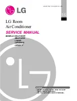
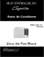
background image

LG 

Room

Air Conditioner

SERVICE MANUAL

LG

MODELS: LW1800PR

LW1800ER
LW1800ERZ3
LW1500PR
LW1500PRY3
LWP1830WAL
LWP1820PDL
LWP1820PEL
LWC182PLMM0
LWC183PLMD1
LWC212PLMM0
LW1804ER
LW1800PRZ3
HBLG1803R

CAUTION

website http://www.lgservice.com

• BEFORE SERVICING THE UNIT, READ THE SAFETY 

PRECAUTIONS IN THIS MANUAL.

• ONLY FOR AUTHORIZED SERVICE PERSONNEL.

Summary of Contents for HBLG1803R

Page 1: ...800ERZ3 LW1500PR LW1500PRY3 LWP1830WAL LWP1820PDL LWP1820PEL LWC182PLMM0 LWC183PLMD1 LWC212PLMM0 LW1804ER LW1800PRZ3 HBLG1803R CAUTION website http www lgservice com BEFORE SERVICING THE UNIT READ THE SAFETY PRECAUTIONS IN THIS MANUAL ONLY FOR AUTHORIZED SERVICE PERSONNEL ...

Page 2: ...tall 8 Suggested Tool Requirements 9 Cabinet Installation 10 Operation 12 Function of Controls 12 Disassembly 16 Mechanical Parts 16 Air Handling Parts 17 Electrical Parts 18 Refrigerating Cycle 20 Schematic Diagram 23 Electronic Control Device 23 Wiring Diagram 25 Components Location 26 Troubleshooting Guide 28 Piping System 28 Troubleshooting Guide 29 Electrical Parts Troubleshooting Guide 31 El...

Page 3: ...ndications Meanings of symbols used in this manual are as shown below WARNING CAUTION This symbol indicates the possibility of death or serious injury This symbol indicates the possibility of injury or damage to properties only Be sure not to do Be sure to follow the instruction WARNING Installation Do not use damaged power cord plugs or a loose socket There is risk of fire or electric shock Alway...

Page 4: ...ing and installing the product Sharp edges could cause injury Be especially careful of the case edges and the fins on the condenser and evaporator Do not store or use flammable gas or com bustibles near the air conditioner There is risk of fire or failure of product Be sure the installation area does not deterio rate with age If the base collapses the air conditioner could fall with it causing pro...

Page 5: ...ver Cool W mm inch 660 25 31 32 H mm inch 428 16 27 32 D mm inch 680 26 27 32 Model Dimension ALL MODELS Outside Dimensions This symbol alerts you to the risk of electric shock This symbol alerts you to hazards that could cause harm to the air conditioner This symbol indicates special notes NOTICE Symbols Used in this Manual ...

Page 6: ...6 7 DB 19 4 WB 35 DB 23 9 WB 800g 28 2 oz 670g 23 6 oz 700g 24 7oz 1 070g 37 7oz 700g 24 7 oz 730g 25 7 oz 765g 27oz 3 ROW 11 STACKS LOUVER FIN TYPE 2ROW11STACKS LOUVER FINTYPE 3 ROW 11 STACKS LOUVER FIN TYPE 2 ROW 19 STACKS L BENDED TYPE 2ROW16STACKS L BENDEDTYPE 2 ROW 19 STACKS L BENDED TYPE TURBO FAN PROPELLER TYPE FAN WITH SLINGER RING 3 3 3 3 2 2 2 3 3 6 POLES REMOTE CONTROLLER THERMISTOR VER...

Page 7: ...ust be checked prior to initial starting The following items are especially important check points when the installation is finished 1 Grounding wire Green or Green and Yellow is provided in the power cord The green wire must be grounded 2 Connect to a single outlet 15A circuit or 20A circuit for Electric Heater Model 3 To avoid vibration or noise make sure the air conditioner is installed securel...

Page 8: ...ear vertical opening of 16 from the bottom of the upper sash to the window stool 2 Installation Kits Contents 29 to 41 18 min Stool Interior wall 26 min Without frame curtain Offset Less 11 4 Sill Exterior Foam PE Adhesive Backed Foam PE Adhesive Backed Type C 5 Type D 2 Type A 14 Carriage Bolt 2 Lock Nut 4 Type B 7 Foam strip Plain Back Right frame curtain Drain pipe Window locking bracket Left f...

Page 9: ...am Seal to the underside of the window sash 4 Remove the backing from Foam PE with 3 holes and attach it to the bottom of the Top retainer bar 5 Attach the Top retainer bar onto the top of the cabinet with 3 screws Type A 6 Insert the Frame guides into the bottom of the cabinet 7 Insert the Frame Curtain into the Top retainer bar and Frame guides 8 Fasten the curtains to the unit with 10 screws Ty...

Page 10: ...s outward CAUTION Do not drill a hole in the bottom pan The unit is designed to operate with approximately 1 2 of water in bottom pan 4 Pull the bottom window sash down behind the Top retainer bar until they meet 1 Do not pull the window sash down so tightly that the move ment of Frame curtain is restricted Attach the cabinet to the window stool by driving the screws Type B through the cabinet int...

Page 11: ...the Window locking bracket with a screw Type C See Fig 13 10 Attach the front grille to the cabinet by inserting the tabs on the grille into the tabs on the front of the cab inet Push the grille in until it snaps into place See Fig 14 11 Lift the inlet grille and secure it with a screw Type A through the front grille See Fig 14 12 Window installation of room air conditioner is now completed Power ...

Page 12: ... LW1500PR LWP1830WAL LW1804ER LW1500PRY3 LW1800PRZ3 POWER BUTTON To turn the air conditioner ON push the button To turn the air conditioner OFF push the button again This button takes priority over any other buttons ROOM TEMPERATURE SETTING BUTTON This button can automatically control the temperature of the room The temperature can be set within a range of 60 F to 86 F by 1 F 16 C to 30 C by 1 C S...

Page 13: ... button is pressed again Set the fan speed with the remote control You can select the fan speed in three steps high low or medium Each time the button is pressed the fan speed mode is shifted If you press the only Air Purifier button only air purifying operates Then fan speed is low You can select the fan speed in three steps high low or medium Each time the button is pressed the fan speed mode is...

Page 14: ...mber for lower temperature of the room OPERATION MODE SELECTION BUTTON Every time you push this button it will shift among COOL ENERGY SAVER FAN and DRY Energy Saver If Energy Save mode is selected the fan stops when the compressor stops cooling Approximately every 3 minutes the fan will turn on and check the room air to determine if cooling is needed FAN SPEED SELECTOR Every time you push this bu...

Page 15: ...TTON Select Cooling Heating or Fan mode with this button FAN SPEED SELECTOR Select the fan speed Cooling Model 3 steps High F3 Low F1 Med F2 High F3 Heating Model 2 steps High F2 Low F1 High F2 ON OFF TIMER BUTTON Set the time of starting and stopping operation The timer is set by 1 hour SIGNAL RECEIVER AUTO SWING The vertical louver swings horizontally by the automatic system and stops when you p...

Page 16: ... the grounding screw from the evaporator channel 5 Remove the 1 screw that fastens the control box cover 6 Remove the housing that connects PCB and motor wire in the control box 7 Disconnect the housing that connects Plazma Air Purifier Optional 8 Remove the screw at left cover of filter case and open the cover to remove inner screw Optional 9 Remove the nut that fastens the terminal cover 10 Remo...

Page 17: ...ll out the hook of orifice by pushing the tabs and remove it See Figure 20 11 Remove the clamp with a hand plier that secures the turbo fan 12 Remove the turbo fan 13 Remove the 2 screws that fasten the air guide from the base pan 14 Move the air guide backward and pull out from the base pan Move the air giude lower carefully 15 Re install the components by referring to the removal procedure above...

Page 18: ...bove 8 Compressor 1 Remove the cabinet Refer to section 2 2 Discharge the refrigerant system using a FreonTM Recovery System If there is no valve to attach the recovery sys tem install one such as a WATCO A 1 before venting the FreonTM Leave the valve in place after servicing the system 3 Remove the overload protector Refer to sec tion 7 4 After purging the unit completely unbraze the suction and ...

Page 19: ...ut the power cord 6 Re install the component by referring to the above removal procedure above Use only one ground marked hole for ground connection 7 If the supply cord of this appliance is damaged it must be replaced by the special cord The special cord means the cord which has the same specification marked on the supply cord attached at the unit DEF ROST HEAT COOL IN DOOR DES IR ED EN ER GY SA ...

Page 20: ...abinet Refer to section 2 2 Remove the 4 screws that fasten the brace Refer to section 4 3 Remove the 5 screws that fasten the condenser and shroud 4 After discharging the refrigerant completely unbraze the interconnecting tube at the con denser connections 5 Remove the condenser 6 Re install the components by referring to notes See Figure 28 13 Evaporator 1 Remove the control box Refer to section...

Page 21: ... pump and place it on the charging cylinder See figure 30B Open valve C Discharge the line at the manifold connection 5 The system is now ready for final charging 6 Recharge as follows 1 Refrigeration cycle systems are charged from the High side If the total charge cannot be put in the High side the balance will be put in the suction line through the access valve which you installed as the system ...

Page 22: ...of making a vapor proof seal Leak detector Tubing cutter Hand Tools to remove components Service valve A COMPOUND GAUGE EVAPORATOR LOW PRESSURE SIDE COMPRESSOR CAPILLARY TUBE CONDENSER HIGH PRESSURE SIDE SEE INSETS BELOW MANIFOLD GAUGE B Figure 30A Pulling Vacuum Figure 30B Charging A B EXTERNAL VACUUM PUMP A CHARGING CYLINDER LOW HI B C ...

Page 23: ...c R04G 4 d R05G 5 e R06G 6 f R07G 7 g 11 10 9 8 Tx ION MED HI KEY0 KEY1 LED out0 LED out1 LED out2 LED out3 Buzzer 5V 1 3 5 7 9 1 3 5 7 9 1 3 1 3 COMP d e g c a f b d e g c a f b d e g c a f b D01G SW01G TEMP DOWN SW02G D02G ON OFF SW03G D03G TIMER SW04G D04G MODE SW05G D05G TEMP UP SW06G D06G FAN HERM C RY COMP G4A 1A E LG RY HI RY MED RY LOW RY 4WAY CN TELE Q01T C104M Q02T A104M 5V Q04T A104M Q0...

Page 24: ...02L ULN2004A 16 15 14 3 6 680pF C01L R01P 20K 50V 3 Digit0 5 10 a f a b Digit1 a 3 9 b 8 c d f d e d c 7 e 4 f 1 g e 6 g g COOL DEFROST DRY HEAT TIMER FAN E SAVER R02G R03G R04G R01G 680 680 680 680 R05G R06G R07G 12V 680 680 680 IC01G 15 14 13 4 3 2 16 1 12 11 10 7 6 5 9 8 ULN2004A 10K 5V 5V R12F R01E 1K 5V C06D BZ01E PKM13EPY 4002 C05D 50V 10V 220 0 01 10 12V 11 12 CN AC DC 51581 12 YEONHO 52044...

Page 25: ...R RY HI RY MED RY LOW CN TH2 RY 4WAY CN 4WAY REVERSING VALVE POWER TRANS SWITCH DC12V CN 12V H V ASSEMBLY BK RD AIR FILTER ASSEMBLY AC PCB ASSEMBLY RY COMP CN PWR CN HVB WIRING DIAGRAM OLP BL COMP WH BL Ribbed BK BR Plain RD BK OR BR YL CAPACITOR HIGH PRESSURE SWITCH CN P S ZNR01J FUSE 250V T2A 115V T2A SOLENOID VALVE 5 1 2 3 4 7 6 5 1 2 3 4 7 6 8 MOTOR COMP CAPACITOR DC PCB ASSEMBLY THERMISTOR AI...

Page 26: ...5D IC01D HEAT SINK QIC02DT J5 Q01T CN TELE CN TH2 CN PWR CN MOTOR ZNR01J CN 4WAY C01J R01J E03J E04J POWER TRANS FUSE RY COMP E05J E02J J8 E01J J6 J2 J3 RY HI ASSEMBLY 6871A20167 RY MED RY LOW RY 4WAY J7 J4 J1 D01T C02T Q02T CN CON CN 12V CN AC DC J12 J13 RECEIVER C02L J21 J22 J23 J18 J19 J17 BZ01E SW03G POWER SW06G TEMP UP SW02G TEMP DOWN SW05G MODE SW01G FAN SPEED C05D J04 CN AC DC J05 J01 J02 R...

Page 27: ...Service Manual 27 Schematic Diagram MODEL LW1800ER LWP1820PDL LWP1820PEL MODEL LW1804ER LW1500PRY3 LW1800PRZ3 LWC183PLMD1 ...

Page 28: ...cooling cycle MOTOR COMPRESSOR OIL LIQUID REFRIGERANT CAPILLARY TUBE OUTSIDE COOLING AIR FOR REFRIGERANT PASS THROUGH SUCTION LINE COOL LOW PRESSURE VAPOR COOLED AIR COMPLETE LIQUID BOIL OFF POINT LIQUID PRESSURE DROP ROOM AIR HEAT LOAD VAPOR INLET HOT DISCHARGED AIR LIQUID OUTLET HIGH PRESSURE VAPOR LIQUID REFRIGERANT LOW PRESSURE VAPOR ROOM AIR CONITIONER EVAPORATOR COILS CONDENSER COILS CYCLE O...

Page 29: ... operation Check gas leakage Repair gas leak Replacement of unit if the unit is beyond repair Satisfactory operation with temperature difference of inlet outlet air 44 50 F 7 10 C Check heat load increase Clean condenser Not on separate circuit Check inside gas pressure Adjusting of refrigerant charged Malfunction of compressor Replacement of compressor Check cold air circulation for smooth flow D...

Page 30: ...rregular motor insulation Replacement of fan motor Regular but fails to start Replacement of compressor locking of rotor metal Improper thermostat setting Loose terminal connection Improper wiring Irregular motor resistance Irregular motor insulation Replacement of compressor Motor damaged Drop of power voltage Capacitor check Replacement Compressor only fails to start Defect of compressor capacit...

Page 31: ...of IC02D DC 5V Is the voltage No 18 of Micom DC 5V Replace AC PCB Ass y Is the connection between AC and DC OK Is the reset circuit OK The No 14 of Micom is 5V Check the Main PCB pattern Replace the Trans Replace D02D D05D Replace IC01D Replace IC02D Replace IC01A C02A Connect connector exactly Check the PCB pattern NO NO NO NO NO NO NO YES YES YES YES YES YES YES NO YES Possible Trouble 1 The uni...

Page 32: ...Room Temp 0 5 C Is the voltage No 10 of IC01M 0V Replace IC01M Select the setting Temp to lower Number Wait 3 Minutes Does the Unit delay for 3 minutes Replace MAIN PCB Ass y Is the voltage N0 9 of IC01M DC 12V Check the RY COMP Check the wiring Diagram NO NO NO YES YES YES YES Is the wire connection of RY COMP OK Check the RY COMP Connect LEAD Wire to RY COMP again NO YES NO ...

Page 33: ... 1 or 2 or 4 of IC01M DC 12V Is the voltage NO 16 or 15 or 13 of IC01M 0V Check the RY Hi or RY Med or RY Lo Check the wiring diagram NO NO YES YES NO NO YES YES Is the mode key pushed once more from cool mode Is the voltage No 3 of CN AC DC of AC PCB Ass y DC 5V Reference to OWNER S MANUAL Set the mode key to Energy Saver mode Check the Energy Saver mode key Check the pattern of AC DC PCB ...

Page 34: ... the DC PCB Ass y Replace IC01G Replace IC03G Q01G Q02G Q03G for Delux Model Connect connector to CN AC DC exactly Does the IC03G Q01G Q02G Q03G for Delux Model operate normally on DC PCB Ass y Is the voltage of Battery over 2 3V Replace Receiver Ass y Is the connection of CN AC DC OK Is the voltage No 10 of CN AC DC on DC PCB Ass y DC 5V Replace the battery Connect connector to CN AC DC exactly N...

Page 35: ...tput Voltage of IC02D DC 5V Is the voltage No 40 of Micom DC 5V Replace AC PCB Ass y Is the connection between AC and DC OK Is the reset circuit OK The No 14 of Micom is 5V Check the AC PCB pattern Replace the Trans Replace D02D D05D Replace IC01D Replace IC02D Replace IC01A C01A Connect connector exactly Check the PCB pattern NO NO NO NO NO NO NO YES YES YES YES YES YES YES NO YES Possible Troubl...

Page 36: ...n Room Temp 0 5 C Is the voltage No 10 of IC01M 0V Replace IC01M Select the desired Temp to lower Number Wait 3 Minutes Is the Unit for 3 minutes delay Replace AC PCB Ass y Is the voltage N0 9 of IC01M DC 12V Check the RY COMP Check the wiring Diagram NO NO NO YES YES YES YES Is the wire connection of RY COMP OK Check the RY COMP Connect LEAD Wire to RY COMP again NO YES NO ...

Page 37: ... or 4 of IC01M DC 5V Is the voltage NO 16 or 15 or 13 of IC01M 0V Check the RY Hi or RY Med or RY Lo Check the wiring diagram NO NO YES YES Is the voltage of Battery over 2 3V Replace Receiver Ass y Is the connection of CN AC DC OK Is the voltage No 10 of CN AC DC on AC PCB Ass y DC 5V Replace the battery Check the PCB pattern Connect connector to CN AC DC exactly NO NO NO YES YES YES ...

Page 38: ... It displays abnormally on DC PCB Ass y NO NO NO NO YES YES YES Are the IC01G and IC02G good Is the connection of CN AC DC OK Replace the DC PCB Ass y Replace IC01G IC02G Replace IC03G Connect connector to CN AC DC exactly Does IC03G operate normally on AC PCB Ass y ...

Page 39: ... Does the fan blade rotate freely If not replace fan motor Pay attention to any change from high speed to low speed If the speed does not change replace the motor If cracked out of balance or partially missing replace it If cracked out of balance or partially missing replace it Tighten it If knocking sounds continue when running or loose replace the motor If the motor hums or noise appears to be i...

Page 40: ...um cleaner do not damage fins or brush Clean the interior base before reassembling If condenser fins are closed over a large area on the coil surface head pressures will increase causing the compressor to overload Straighten the fins or replace the coil Test capacitor Check the terminals If loose repair or replace Check the system for a restriction If restricted clean of replace Close if open Dete...

Page 41: ...268714 268712 238310 W0CZZ 135500 249950 147581 147582 1 559010 352111 352113 W52106 1 263230 237200 W48602 148000 349600 354210 152312 267110 152302 264110 130410 550140 35211A 554160 567502 135312 135303 554031 TIME R MO DE TE MP PO WER FA N SP EE D 147582 2 W52106 2 C TIMER PO WER MODE TE MP FA N SP EE D F1 LOW F2 ME D F3 HIG H Dr y Timer Fa n En erg y Sa ver Co ol 352390 2 352390 1 COOLING MOD...

Page 42: ... DR Y 130910 149980 346811 359012 W48602 349480 349001 268714 268712 238310 W0CZZ 135500 249950 147581 147582 1 559010 552111 352115 1 263230 237200 W48602 148000 349600 354210 152312 152302 264110 130410 550140 554160 567502 135312 135303 554031 TIMER MOD E TE MP PO WER FA N SP EE D 147582 2 352115 2 352390 2 35211A 566000 552202 352113 267110 352390 1 ...

Page 43: ...NTROLLER ASSEMBLY 6711A20052A 268712 PWB PCB ASSEMBLY MAIN DC 6871A20323A 268714 PWB PCB ASSEMBLY MAIN AC 6871A20271B 349001 DAMPER VENTILATION 4900A20004A 349480 ORIFICE 4948A30008A 349600 MOUNT MOTOR 4960AR2895B 352113 TUBE ASSEMBLY DISCHARGE SINGLE 5211A30066N 35211A TUBE ASSEMBLY SUCTION OUTDOOR 5211A20441A 352390 1 AIR GUIDE ASSEMBLY 5239A20002A 352390 2 AIR GUIDE ASSEMBLY 5239A20003A 354210 ...

Page 44: ...20271C R 346811 MOTOR ASSEMBLY SINGLE 4681AR6033V 4681AR6033V 4681A20081G R 349001 DAMPER VENTILATION 4900A20004A 4900A20004A 4900A20004A R 349480 ORIFICE 4948A30008A 4948A30008A 4948A30008A R 349600 MOUNT MOTOR 4960AR1596A 4960AR1596A 4960AR1596A R 352111 TUBE ASSEMBLY CAPILLARY 5211A30275J 5211A30275V 352113 TUBE ASSEMBLY DISCHARGE SINGLE 5211A30066T 5211A30066T 5211A20805J R 352115 1 TUBE FORME...

Page 45: ...Y SUCTION OUTDOOR 5211A20441C 5211A20441A R 352111 TUBE CAPILLARY 5211AR3399L R 352113 TUBE ASSEMBLY DISCHARGE SINGLE R 352115 1 TUBE FORMED EVAPORATOR 5211A20215G R 352115 2 TUBE FORMED EVAPORATOR 5211A20215H R 35211A TUBE ASSEMBLY SUCTION OUTDOOR R 352390 1 AIR GUIDE ASSEMBLY 5239A20002A 5239A20002A R 352390 2 AIR GUIDE ASSEMBLY 5239A20003A 5239A20003A R 354210 EVAPORATOR ASSEMBLY FIRST 5421A200...

Page 46: ...A20011J 6411A20011K R 346811 MOTOR ASS Y 4681AR6033V 4681AR6033X 4681AR6033V R 349001 VENTILATION DAMPER 4900A20004A R 349480 ORIFICE 4948A30008A R 349600 MOUNT MOTOR 4960AR1596A R 352111 TUBE ASS Y CAPILLARY 5211AR3332Z 5211A30275F 5211AR3399L R 352113 DISCHARGE TUBE 5211A30066N 5211A30066R 5211A30066N R W52106 1 TUBE FORMED EVAPORATOR 5210A21099A 5210A21099E R W52106 2 TUBE FORMED EVAPORATOR 521...

Page 47: ...871A20167F R 346811 MOTOR ASSEMBLY SINGLE 4681AR6033Y R 349001 DAMPER VENTILATION 4900A20004A R 349480 ORIFICE 4948A30008A R 349600 MOUNT MOTOR 4960AR1596A R 35211A TUBE ASSEMBLY SUCTION OUTDOOR R 352111 TUBE CAPILLARY 5425AR3147H R 352115 1 TUBE FORMED EVAPORATOR 5210A21099N R 352115 2 TUBE FORMED EVAPORATOR 5210A21099P R 352390 1 AIR GUIDE ASSEMBLY 5239A20002C R 352390 2 AIR GUIDE ASSEMBLY 5239A...

Page 48: ...3C 6871A20323C 268714 PWB PCB ASSEMBLY MAIN AC 6871A20167L 6871A20167L 346811 MOTOR ASSEMBLY SINGLE 4681A20011M 4681A20011M 349001 DAMPER VENTILATION 4900A20004A 4900A20004A 349480 ORIFICE 4948A30008A 4948A30008A 349600 MOUNT MOTOR 4960AR2895B 4960AR2895B 352113 TUBE ASSEMBLY DISCHARGE SINGLE 5211A30066N 5211A30066N 352115 1 TUBE EVAPORATOR 5210A21099A 5210A21099A 352115 2 TUBE EVAPORATOR 5210A210...

Page 49: ...LY 6711A90019C 268712 PWB PCB ASSEMBLY MAIN AC 6871A20167D 268714 PWB PCB ASSEMBLY MAIN DC 6871A20325A 346811 MOTOR ASSEMBLY SINGLE 4681A20011M 349001 DAMPER VENTILATION 4900A20004A 349480 ORIFICE 4948A30008A 349600 MOUNT MOTOR 4960AR2895B 352111 TUBE CAPILLARY BEND 5210A20492R 352113 TUBE ASSEMBLY DISCHARGE SINGLE 5211A30066N 352390 1 AIR GUIDE ASSEMBLY 5239A20002A 352390 2 AIR GUIDE ASSEMBLY 523...

Page 50: ...P No 3828A20140E Printed in Korea ...

Reviews: