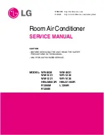
LG HBLG1453E, Service Manual
The LG HBLG1453E Service Manual is a comprehensive guide that allows you to troubleshoot and repair your LG appliance. With step-by-step instructions and detailed diagrams, this manual assists you in maintaining your product's optimal performance. Download it for free from manualshive.com and get the most out of your device.
Share
Download


Reviews:
No comments
Related manuals for HBLG1453E

FTK09NMVJU
Brand: Daikin Pages: 92
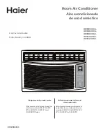
HWE08XCR-L
Brand: Haier Pages: 56
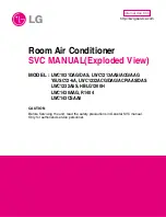
HBLG1200H
Brand: LG Pages: 26
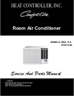
COMFORT-AIRE REG-123A
Brand: LG Pages: 31
COMFORT-AIRE REG-123A
Brand: LG Pages: 49
HBLG1803R
Brand: LG Pages: 50
HBLG2504E
Brand: LG Pages: 39
L1804R
Brand: LG Pages: 12
L1804R
Brand: LG Pages: 53
L1804R
Brand: LG Pages: 39
LW1000ER
Brand: LG Pages: 18
LW1000ER
Brand: LG Pages: 46
LW1200ER
Brand: LG Pages: 18
LWC1213AAG
Brand: LG Pages: 32
LWHD2500ER
Brand: LG Pages: 2
LWHD2500ER
Brand: LG Pages: 48
WM-1231
Brand: LG Pages: 35

CS-VC125KE
Brand: Panasonic Pages: 29


