background image

ELECTRIC & GAS DRYER

SERVICE MANUAL

CAUTION

READ THIS MANUAL CAREFULLY IN ORDER TO
PROPERLY DIAGNOSE PROBLEMS AND TO SAFELY
PROVIDE QUALITY SERVICE ON THESE DRYERS.

MODEL : GD1329CGS/GD1329CES

GD1329CGU/GD1329CEU
GD1329CGD/GD1329CED
GD1329QGS/GD1329QES
GD1329QGU/GD1329QEU
GD1329QGD/GD1329QED

C

E R

T I F I E

D

D E

S I G N

Summary of Contents for / GD1329QES

Page 1: ...L CAREFULLY IN ORDER TO PROPERLY DIAGNOSE PROBLEMS AND TO SAFELY PROVIDE QUALITY SERVICE ON THESE DRYERS MODEL GD1329CGS GD1329CES GD1329CGU GD1329CEU GD1329CGD GD1329CED GD1329QGS GD1329QES GD1329QGU GD1329QEU GD1329QGD GD1329QED C E R T I F I E D DE S I GN ...

Page 2: ...MARCH 2010 PRINTED IN KOREA P No MFL62119919 ...

Page 3: ...ems are present everywhere ESD may damage or weaken the electronic control assembly The new control assembly may appear to work well after repair is finished but failure may occur at a later date due to ESD stress Use an anti static wrist strap Connect wrist strap to green ground connection point or unpainted metal in the appliance OR Touch your finger repeatedly to a green ground connection point...

Page 4: ...PLY 47 15 2 TEST 2 THERMISTOR TEST 50 15 3 TEST 3 MOTOR TEST 51 15 4 TEST 4 MOISTURE SENSOR 52 15 5 TEST 5 DOOR SWITCH TEST 53 15 6 TEST 6 HEATER SWITCH TEST ELECTRIC MODEL 54 15 7 TEST 7 GAS VALVE TEST GAS MODEL 55 16 ERROR MODE 56 17 CHANGE GAS SETTING NATURAL GAS PROPANE GAS 57 18 DISASSEMBLY INSTRUCTIONS 60 19 EXPLODED VIEW 68 19 1 1 Control Panel Plate Assembly Coin Type 68 19 1 2 Control Pan...

Page 5: ...a around the exhaust opening and adjacent surrounding areas free from the accumulation of lint dust and dirt The interior of the dryer and exhaust vent should be cleaned periodically by qualified service personnel Do not install or store the dryer where it will be exposed to the weather Always check the inside of the dryer for foreign objects Clean lint screen before or after each load Your Safety...

Page 6: ...O DO IF YOU SMELL GAS CALIFORNIA SAFE DRINKING WATER AND TOXIC ENFORCEMENT ACT This act requires the governor of California to publish a list of substances known to the state to cause cancer birth defects or other reproductive harm and requires businesses to warn customers of potential exposure to such substances Gas appliances can cause minor exposure to four of these substances namely benzene ca...

Page 7: ...o the equipment grounding terminal or lead on the appliance Electrical shock can result if the dryer is not properly grounded SAFETY INSTRUCTIONS FOR INSTALLATION Properly ground dryer to conform with all governing codes and ordinances Follow details in the installation instructions Electrical shock can result if the dryer is not properly grounded Before use the dryer must be properly installed as...

Page 8: ...he end cap should have hinged dampers to prevent backdraft when the dryer is not in use Failure to follow these instructions can result in fire or death The exhaust duct must be 4 in 10 cm in diameter with no obstructions The exhaust duct should be kept as short as possible Make sure to clean any old ducts before installing your new dryer Failure to follow these instructions can result in fire or ...

Page 9: ...ectrical shock hazard and or a fire hazard The dryer should always be plugged into its own individual electrical outlet which has a voltage rating that matches the rating plate This provides the best performance and also prevents overloading house wiring circuits which could cause a fire hazard from overheated wires Never unplug your dryer by pulling on the power cord Always grip plug firmly and p...

Page 10: ...e refer to the rating label regarding detailed information Size 686mm W x 764mm D x 983mm H 27 W X 30 3 4 D X 38 11 16 H Capacity IEC 7 1 cu ft 22 5 lb Weight 131 Ibs 59 4 kg Specifications are subject to change by manufacturer 2 SPECIFICATIONS ...

Page 11: ...xHxD Packing WxHxD 120 240V 24 Amps White Painted Stainless Deco Hair line Chrom White 420W 4 5V 5400W 22 5A 13W 110mA x 2 Electronic IEC 7 1 cu ft 126 144 4 Available Available Available Alcosta 686mm W x 764mm D x 983mm H 29 7 10 W x 44 7 10 H x 31 2 5 D Inch Color MATERIAL FINISH ELECTRICITY CONSUMPTION Top Plate Door Trim Door Frame C Panel Color MOTOR HEATER GAS VALVE Electric 120V 7 Amps AC ...

Page 12: ...TS CARD TYPE SIDE BY SIDE GD1329CGS GD1329CES STACK UPPER GD1329CGU GD1329CEU STACK LOWER GD1329CGD GD1329CED 1 DISPLAY LED 2 CYCLE BUTTON 3 START BUTTON 4 STATUS LED 1 2 4 3 COIN TYPE SIDE BY SIDE GD1329QGS GD1329QES 1 2 4 3 ...

Page 13: ...12 COIN TYPE STACK LOWER GD1329QGD GD1329QED COIN TYPE STACK UPPER GD1329QGU GD1329QEU 1 DISPLAY LED 2 CYCLE BUTTON 3 START BUTTON 4 STATUS LED 1 2 4 3 1 2 4 3 ...

Page 14: ...placed firmly on a solid and even floor If the dryer is not level the clothes will not tumble properly and the sensor will not be able to detect the dryness level accurately Adjust the leveling legs carefully to avoid injury Note No other fuel burning appliance shall be installed in the same closet as the dryer This applies only to dryers suitable for installation in a closet WARNING The appliance...

Page 15: ...ryer until it is level from left to right and from front to back The leveling legs must remain firmly on the floor and the dryer should not rock The maximum slope of the dryer from left to right or from front to back should not exceed 2 5 cm 1 inch If the dryer is not level and if the slope exceeds 2 5 cm 1 inch a load may not tumble properly and internal sensors may malfunction Note Other section...

Page 16: ...d PLEASE BE AWARE THAT FAILURE TO EXHAUST THE DRYER CORRECTLY WILL VOID THE DRYER S WARRANTY WARNING Use a heavy metal vent Do not use plastic or thin foil duct Clean old ducts before installing this dryer Failure to follow these instructions can result in death or fire ALTERNATE EXHAUST DIRECTIONS 1 Remove the screw that attaches the duct s tab to the dryer 2 1 Detach and remove the knockout that...

Page 17: ... Dryer It is important that you thoroughly review that section and the remainder of this manual before taking any steps to install or use this dryer 1 Use only a new U L listed No 10 copper wire only three conductor power supply cord kit rated 240 Volts minimum 30 Amperes and labeled as suitable for use in a clothes dryer 2 Four wire cord is required for manufactured mobile home installations and ...

Page 18: ...rt the dryer on a heat setting as described more fully in the operating instructions that accompany the dryer After the dryer starts the igniter will glow red and the main burner will ignite Confirming Heat Source in Electric Dryers Close the door to the dryer drum drying compartment and after completing all steps in this manual for proper installation of this dryer start the dryer on a heat setti...

Page 19: ...ng the back left or bottom panel Gas dryer may not be vented to the outside using the right side panel because of the burner housing 6 The dryer exhaust duct must be affixed securely to the manufactured or mobile home structure and the exhaust duct must be made of a material that will resist fire and combustion and it is recommended that you use a rigid or flexible metal pipe 7 DO NOT connect the ...

Page 20: ...d 3 3 CARD TYPE Single WARNING Disconnect power before service Failure to follow these instructions can result in death or electrical shock When power on the machine at first time without connecting card reader or coin housing display will show LqC1 2 2 COIN TYPE Coin housing Card reader housing Card reader housing The Coin drop assembly operates on DC12V in dryer The Card reader assembly operates...

Page 21: ...Disassemble the control plate Disconnect the connectors Remove 2 screws Disassemble the top plate Remove 4 pieces 20 4 4 STACK TYPE Installation Method Dryer Coin Type Lower Stacking Coin ...

Page 22: ...ess on the back of the coin box Face it toward the front so the coin box will press the button when it is in place Use an adhesive tie fastener and a cable tie to affix the service switch to the front panel The connectors should be visible on the rear of the box for connection to the harness later Connect the coin box switch at this time ...

Page 23: ...22 Assemble the security bracket Attach the security lock bracket if it wasn t Installed at the factory Assemble the top plate Install the top plate on the dryer ...

Page 24: ... Remember this is the TOP dryer when they are stacked Stack the machine Stack the upper dryer onto the lower dryer Remove the lower panel from the upper dryer Disassemble the lower panel frame Connect the bolt Installation Method Dryer Coin Type Upper Stacking Coin ...

Page 25: ...24 Disassemble the lower panel frame Remove the lower control panel Remember this is the TOP dryer when they are stacked Coin Harness provided by ESD ...

Page 26: ... to the upper dryer and secure the wiring harness Route the wiring to the lower control panel Be careful to avoid confusing the upper and lower harness After installing the coin drop module and coin box replace the front panels on both machine Be sure to secure all wiring harness parts to avoid vibration pinching chafing or other Damage using adhesive blocks and cable ties Coin Drop provided by ES...

Page 27: ...te Upper Attach the control panel with the dual coin drop module to the bottom of top dryer Assemble the control plate Lower Install security lock Attach the control panel with coin drop box module to the top of the bottom dryer ...

Page 28: ...llation Method Dryer Card Type Stacking Card Different point between Coin type and Card type Install the stacking bracket at the rear of the stacked dryers There are six 6 screws that hold the assembly in place ...

Page 29: ...n on gas and check all pipe connections internal external for gas leaks with a non corrosive leak detection fluid 5 For L P Liquefied Petroleum gas connection refer to section on Gas Requirements For further assistance refer to section on Gas Requirements 1 New Stainless Steel Flexible Connector Use only if allowed by local codes Use Design A G A Certified Connector 2 1 8 N P T Pipe Plug for check...

Page 30: ...d dryer terminal block IS NOT supplied with dryer Type of pigtail and gauge of wire must conform to local codes and with instructions on the following pages Failure to follow these instructions can result in fire explosion or death A 4 wire connection is required for all mobile and manufactured home installations as well as all new construction after January 1 1996 A 4 wire connection must be used...

Page 31: ...Wire Power Cord Terminal Block Ground Screw Neutral White Hot Black Power Cord Ground Wire Hot Red A 4 wire connection is required for all mobile and manufactured home installations as well as all new construction after January 1 1996 A UL listed strain relief is required Use a 30 amp 240V UL listed power cord with 10 AWG minimum copper conductor and closed loop or forked terminals with upturned e...

Page 32: ...l a UL listed strain relief into the power cord through hole then thread the power cable prepared in Step 1 through the strain relief 2 UL Listed Strain Relief UL Listed 4 Wire Power Cord Terminal Block 5 12 7 cm 1 2 5 cm Four Wire Connection for Electric Dryers Direct Wire A 4 wire connection is required for all mobile and manufactured home installations as well as all new construction after Janu...

Page 33: ...ruction after January 1 1996 A UL listed strain relief is required Use a 30 amp 240V UL listed power cord with 10 AWG minimum copper conductor and closed loop or forked terminals with upturned ends Ground Screw UL Listed Strain Relief UL Listed 3 Wire Power Cord Terminal Block Ground Wire Hot Black Hot Red Neutral White WARNING Connect the power cord to the terminal block Each colored wire should ...

Page 34: ...power cable prepared in Step 1 through the strain relief 2 UL Listed Strain Relief UL Listed 3 Wire Power Cord Terminal Block 1 2 5 cm A 3 wire connection is NOT permitted on new construction after January 1 1996 A UL listed strain relief is required Use UL listed 3 wire 10 AWG minimum copper conductor cable Allow at least 5 ft 1 5 m length to allow for removal and reinstallation of the dryer WARN...

Page 35: ...shers and dryers and DO NOT operate a washer and a dryer on the same circuit a The dryer has a three prong plug to help guard against shock The plug should be plugged directed into a properly grounded three prong receptacle that is rated 120 Volts AC alternating current 15 Amps This plug in order to be properly and fully effective must be plugged into a properly installed outlet that is grounded i...

Page 36: ...uld be 1 2 inch IPS If acceptable under local codes and ordinances and when acceptable to your gas supplier 3 8 inch approved tubing may be used where lengths are less than 20 feet 6 1 m Larger tubing should be used for lengths in excess of 20 feet 6 1 m It is also important that you use pipe joint compound that is insoluble in LP gas 6 To reduce the danger of gas leaks explosion and fire please f...

Page 37: ...n the dryer and and the wall In special installations when it is impossible to make a connection with the above recommendations then a UL listed flexible metal transition duct may be used between the dryer and wall connection only The use of this ducting will affect dry time 4 DO NOT use sheet metal screws on exhaust pipe joints or other fastening means which extend into the duct that could catch ...

Page 38: ...nd it will be cause of trouble Follow the below guide in case of using gathering exhaust duct installed with over 2 duct Incline the exhaust duct toward exit about an 45 angle when exhaust duct from dryer is connected to main exhaust duct If you don t make perpendicular connection airflow is disturbed Over sum of area A B C D Exit Inspection Cap Over sum of area A B C Over sum of area A B Over are...

Page 39: ...RCED MULTIPLE VENTING SYSTEM Use adjust damper to fit airflow velocity 5m s at exit Gas Dryer Exhaust duct Exhaust duct Main Exhaust Duct Adjust Damper Blower Suction fan Outdoor Exit Air flow velocity 5m s ...

Page 40: ...n when servicing the dryer because wiring errors can cause serious injury to you and your dryer 1 Clean the lint filter either before drying each load or after drying each load Always make sure the lint filter is clean before starting a new load because a clogged lint filter may increase drying times 2 To clean pull the lint screen straight up and roll any lint off the screen with your fingers Do ...

Page 41: ...e Dry More Dry Saturation Saturation Saturation 45 min 45 min 45 min 2 min 2 min 2 min 68 4 C 60 4 C 52 3 C 47 5 C 47 5 C 38 5 C Time Dry LOAD Default Drying Electro sensor Temp Control Default time Temp Control Cooling Conditions of operation and termination Temp erature Dry Level Display time Temperature Control for each cycle ...

Page 42: ... of terminal to terminal Open at 185 9 F 85 5 C Close at 149 9 F 65 5 C Same shape as Thermal cut off Resistance value Resistance value 5Ω Blow housing Safety Electric type 6 Idler switch Measure resistance of the following terminal COM NC 1 lever open Resistance value 1Ω 2 Lever push close Resistance value 5 Door switch Measure resistance of the following terminal 1 Door switch knob open Terminal...

Page 43: ...58 F 10 40 C 58 F 104F 10 40 C Resistance value 10Ω Heater case Hi limit Electric type 9 Motor See Page 13 10 Gas valve valve 1 valve 2 Measure resistance of the following terminal Valve 1 terminal Valve 2 terminal Resistance value 1 5 kΩ Resistance value 1 5 2 5 kΩ Gas type 11 Igniter Measure resistance of terminal to terminal Resistance value 100 800Ω Gas type 12 Frame Detect Measure resistance ...

Page 44: ... terminal Open at 203 7 F 95 5 C Close at 158 9 F 70 5 C Resistance value Continuity 1Ω Gas type Gas funnel 13 Outlet Thermostat Manual reset Check Top Marking N100 Measure resistance of terminal to terminal Open at 212 12 F 100 7 C Manual reset If thermal fuse is open must be replaced Resistance value Continuity 1Ω Gas type Gas funnel ...

Page 45: ...n Motor does not operate RUN MODE Motor operates Centrifugal switch Centrifugal switch Pull Drive forward WARNING When checking the component be sure to turn the power off and do discharge voltage sufficiently Failure to follow these instructions can result in death or electrical shock ...

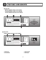
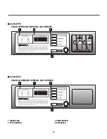
Page 46: ...13 CONTROL LAY OUT 45 PWB ASSEMBLY DISPLAY LAY OUT PWB ASSEMBLY LAY OUT ...

Page 47: ...R B E T I H W L I O C R E N N I L I O C R E T U O W O L L E Y E U L B D E R E T I H W N W O R B BL2 NA6 DOORSWITCH NC NO COM 2 3 1 1 2 3 3 1 1 2 3 OVERLOAD PROTECTOR MOTOR L A G U F I R T N E C H C T I W S T A T S O M R E H T T I M I L I H TABRELAY BLACK TABRELAY WHITE 2 1 3 7 10 D E R E G N A R O E U L B 6 4 2 1 2 1 2 1 THERMISTOR MOISTURE SENSOR E T I H W CAUTION Label all wires prior to disconn...

Page 48: ...nt None 1 time 2 times 3 times 4 times 5 times 6 times During check if the door is open During check if the door is closed Check the version and code of machine ELECTRIC TYPE US OE GAS TYPE US Og Motor runs ELECTRIC TYPE Heater runs Motor Heater 1 2700W GAS TYPE GAS valve runs Motor Valve ELECTRIC TYPE Heater runs Motor Heater 1 Heater 2 5400W GAS TYPE GAS valve runs Motor Valve LED KEY CHECK Pres...

Page 49: ...ed to controller NO NO YES YES YES NO Check the outlet is the voltage 110V 125V AC Check the fuse or circuit breaker Check if power cord is properly connected Reconnect the controller Check if the voltage measured between Connector BK2 or WH2 Black Wire Linked to the Controller and YL3 White Wire Is 110 125V Check if the controller wire is disconnected Check if terminal block and power cord are co...

Page 50: ...ng White Tab Relay White Color Table1 Connection of the Tab Relay with Heater Electric Table 2 Connection of the Tab Relay with Burner Gas Table1 Connection of Tab Relay with the Tab Relay of the PCB ASSEMBLY Electric Harness Connection Remark PCB 1 2 Yellow Wire Black Wire Connector Housing Tap relay 1 Tap relay 2 1 2 Blue Wire Black Wire Connector Housing WARNING When measuring power be sure to ...

Page 51: ... White PCB condition of operation Connector Housing Black Check the matching color between harness wire and tab relay Black Housing Black Tab Relay Color Table 2 Connection of Tab Relay with PCB ASSEMBLY Gas Table1 Wrong Connection of the Tab Relay and Connector Housing Electric Table2 Wrong Connection of the Tab Relay and Connector Housing Gas Harness Remark PCB Tap relay 1 1 2 Blue Wire Black Wi...

Page 52: ...in Connector from the Controller Table 1 Resistance for Thermistor Temperature Check if resistance is in the range of Table 1 when measuring resistance between terminals after separating harness from thermistor assembly connector YES NO Replace thermistor Air TEMP F C 50 F 10 C 60 F 16 C 70 F 21 C 80 F 27 C 18 0 14 2 11 7 9 3 90 F 32 C 100 F 38 C 110 F 43 C 120 F 49 C 7 7 6 2 5 2 4 3 130 F 54 C 14...

Page 53: ...and BL2 Measure while door is closed Yellow wire Is resistance below 3Ω between Connector BL2 Yellow wire and BL2 Brown wire Is resistance below 1Ω between terminals of outlet thermostat attached to blower housing Does idle switch attached to motor bracket operate level by drum belt Not operating lever is normal Is resistance below 1Ω between idler switch terminals Check motor Refer to Motor Diagr...

Page 54: ...Blue Wire and Pin Orange Wire to controller When measuring resistance in electrode load is resistance below 1Ω YES NO When contacting cloth to electrode 1 Is the measurement within the range of Table 2 during diagnostic test 2 Is the measurement within the range of Table 2 when measuring the voltage in the 6 pin connector s Pin BLUE wire and Pin ORANGE wire YES NO Replace control and check Check e...

Page 55: ...d BK2 Connector YL3 BL2 after taking WH1 BL2 out from Controller Measure while door is open Check it resistance is 300 60 Ω between YL3 White wire and BK2 Black wire Connector YL3 BL2 after taking YL3 BL2 out from controller Measure while door is open Check it resistance is below 1 Ω between BL2 Yellow wire and YL3 White wire after taking connector YL3 BL2 out from controller Measure while door is...

Page 56: ...Is resistance between heater terminal and below 18 22Ω 3 Is resistance between heater terminal and below 9 11Ω YES NO Replace heater Check if the value of measured resistance is below 1Ω between terminal TH2 Safety Thermostat YES NO Replace TH2 Safety Thermostat Check if the value of measured resistance is below 1Ω between terminal TH3 HI Limit Thermostat YES NO Replace TH3 HI Limit Thermostat TH3...

Page 57: ...fety Igniter operates after 1 minute igniter becomes reddish YES NO Check igniter flame detect When measuring Valve 2 voltage Value is more than DC 90V 10 sec after Igniter off NO YES Check gas connection or gas supply When measuring Valve 1 voltage More than DC 90V YES NO If valve 1 and Valve 2 are under DC 10V valves are off YES NO Power on start Normal Cycle NO Igniter Valve 2 Valve 1 WARNING W...

Page 58: ...rrence or problem Dryer error code PROBLEM POSSIBLE CAUSE It is displayed when thermistor is open Thermistor should be replaced Thermistor should be replaced Check the card reader wire It is displayed when thermistor is shorted Disconnection of card reader wire SOLUTION ...

Page 59: ...with propane gas orifice Kit contents Orifice Dia 1 613mm for Propane Gas Replace Label Instruction Sheet WARNING Conversion must be made by a qualified technician Changing orifices and gas valve adjustments improperly can result in an explosion and or fire The dryer is shipped from the factory set up and adjusted to operate on natural gas It can be converted to operate on propane LPG The conversi...

Page 60: ...E 1 IGNITER VALVE 2 FLAME DETECT OPEN GAS VALVE STRUCTURE Adjustment Screw GAS VALVE FLOW START KEY PUSH DRYING VALVE 1 ON VALVE 2 ON IGNITER ON IGNITER OFF FLAME DETECT OPEN IGNITER TEMPERATURE ABOUT 370 F GAS IGNITION FLAME DETECT CLOSE VALVE 2 OFF NO NO YES YES ...

Page 61: ...then forward 3 Disconnct the connectors WARNING Disassemble and repair the unit only after pulling out power plug from the outlet Failure to follow these instructions can result in death or electrical shock WARNING When you disassemble the control panel be sure to take gloves and careful panel frame s edge Failure to do so can cause serious injury ...

Page 62: ... screws on the control panel frame 2 Push the top plate backward forcefully 3 Lift the plate WARNING When you disassemble the top plate be sure to take gloves and careful plate s edge Failure to do so can cause serious injury ...

Page 63: ...n the door assembly 2 Remove 2 screws 3 Remove 4 screws from the top of cabinet cover 4 Disconnect the harness of door switch 5 Disassemble the cover cabinet WARNING When you disassemble the door switch connector be sure to take gloves and careful cabinet edge Failure to do so can cause serious injury ...

Page 64: ...l frame 2 Remove 4 screws on the panel frame 3 Disassemble panel frame from pulling upside Push Push LOWER FRAME 1 Disconnect the housing of the panel frame 2 Remove 4 screw on the panel frame 3 Disassemble lower frame from pulling forward with pushing down 63 ...

Page 65: ...he door lamp and electrode sensor connector 4 Remove 4 screws 5 Disassemble the tub drum front TUB DRUM FRONT 1 Disassemble the top plate 2 Remove the cabinet cover and drum front 3 Loosen belt from motor and idler pulleys 4 Carefully remove the drum DRUM ASSEMBLY 1 2 1 ...

Page 66: ...it is available as a service part 383EEL9001B 2 1 Detach and remove a knockout at the botton left or right side as desired Right side vent not available on gas dryer the order of work 3 1 Pre assemble a 4 inch elbow to a piece of duct Wrap duct tape around the joint 3 2 Insert the elbow duct assembly through the side opening and connect the elbow to the internal duct 65 ...

Page 67: ...ve the cabinet cover and drum front 3 Remove the Drum assembly 4 Remove 2 screws and cover air guide 5 Remove the bolt and washer 6 Remove the fan 7 Disconnect the motor clamp and motor BLOWER HOUSING 1 Disassemble the top plate 2 Remove the cabinet cover and drum front 3 Remove the drum assembly 4 Remove 7 screws 5 Remove the back cover BACK COVER ...

Page 68: ...nd 2 screws 4 Remove the air duct AIR DUCT 1 Disassemble the top plate 2 Remove the cover cabinet and tub drum front 3 Remove the drum assembly and tub drum rear 4 Disconnect the air duct from the tub drum front 5 Remove the roller from the tub drum front and tub drum rear Rollers ...

Page 69: ...EXPLODED VIEW 19 19 1 1 Control Panel Plate Assembly Coin Type A210 A120 A110 68 ...

Page 70: ...19 1 2 Control Panel Plate Assembly Card Type A210 A120 A117 A110 69 ...

Page 71: ...19 2 1 Cabinet Door Assembly Electric Stack Upper Type A600 A130 A390 A800 A500 A460 A510 A410 A420 A450 A430 A400 A530 A525 A540 A520 A310 A391 A113 A330 A320 A570 A560 A212 A305 A300 A131 A900 A601 70 ...

Page 72: ... Lower Type A600 A130 A800 A500 A460 A510 A410 A420 A450 A430 A400 A530 A525 A540 A520 A310 A330 A320 A570 A560 A212 A305 A300 A391 A113 A390 A131 Application Model GD1329QED Application Model GD1329QES GD1329QEU GD1329CED GD1329CES GD1329CEU 71 ...

Page 73: ...72 19 2 3 Cabinet Door Assembly Gas Stack Upper Type A600 A550 A800 A500 A460 A510 A410 A420 A450 A430 A400 A530 A525 A540 A520 A310 A330 A320 A212 A305 A300 A900 A391 A113 A390 A131 A601 A130 ...

Page 74: ...ack Lower Type A600 A550 A800 A500 A460 A510 A410 A420 A450 A430 A400 A530 A525 A540 A520 A310 A330 A320 A212 A305 A300 A391 A113 A390 A131 A130 Application Model GD1329QGD Application Model GD1329QGS GD1329QGU GD1329CGD GD1329CGS GD1329CGU ...

Page 75: ...otor Assembly Electric Type K640 K120 K140 K400 F200 K310 K610 K330 K340 K130 K100 K210 K230 K350 K240 F130 F110 F120 F140 K510 K515 K540 K650 K651 K600 K530 K520 K550 K560 K360 K620 K320 K655 K250 K251 K250 K251 74 ...

Page 76: ...M240 M150 M141 M220 M230 M110 M181 M250 M190 K640 K120 K140 K400 F200 K310 K610 K330 K340 K130 K100 K210 K230 K350 K240 K510 K540 K650 K651 K600 K530 K520 K550 K560 K360 K620 K320 K250 K251 K250 K251 K655 M115 K515 M171 Propane Gas orifice M170 Natural Gas orifice 75 ...

Reviews: