background image

CAUTION

BEFORE SERVICING THE UNIT, READ THE "SAFETY 
PRECAUTIONS" IN THIS MANUAL.

WINE CELLER

SERVICE MANUAL

GC-W061***

GC-W101***

GC-W141***

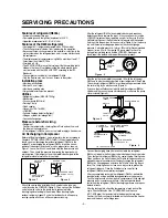
Summary of Contents for GC-W061 series

Page 1: ...CAUTION BEFORE SERVICING THE UNIT READ THE SAFETY PRECAUTIONS IN THIS MANUAL WINE CELLER SERVICE MANUAL GC W061 GC W101 GC W141 ...

Page 2: ...f appliance check regular current voltage and capacity 5 Don t touch deep frozen products in the freezer with wet hands This may cause frostbite 6 Prevent water from following onto electric elements in the mechanical parts 7 When tilting the set remove any materials on the set especially the thin plates ex Glass shelf or books 8 Leave the disassembly of the refrigerating cycle to a specialized ser...

Page 3: ...completely discharged repair any defective parts and replace the dryer At any case you must use the LOKRING for connecting or replacing any part in the cycle No Fire No Welding Connect the Schrader valve to pump with the coupler And then turn the pump on for vacuum state Figure 3 Let the pump run until the low pressure gauge indicates the vacuum gauge pressure 0 absolute pressure 1atm or 760mmHg R...

Page 4: ...irculation Type Temperature Control Device MICOM Outer Case Material Vynil Coated Metal Inner Case Material A B S Resin OUT DOOR Indium Thin Oregan Triple Layers Glasses Aluminium Deco Insulation Material Poly Urethane Foam Insulation Foam Gas Cyclopentane 693 X 717 X 946 693 X 717 X 1296 693 X 717 X 1586 51kg 74kg 81kg Package Exterior Measurement Width X Depth X Height Package Weight Package Det...

Page 5: ... on and off by control panel operation button 2 2 Wine Rack Wine rack detail may vary according to the model types Each rack can hold 8 wine bottles and top rack holds 9 bottles 2 3 Others Glass Holder Hangs wine glasses GC W141 Wine Rack Stores leftover wine tilted GC W141 GC W101 Locking Device Key is enclosed in the inside of the refrigerator Leg Adjustor Front Back Left Right one each Please l...

Page 6: ...fridge can be turned on or off by pressing the button on the operation panel Light bulb inside the wine fridge will automatically turn off after the door is open for an hour Top Bottom Separation Panel The partition is separated into Top partition and Bottom partition based on the top bottom separation panel Temperature is adjusted with Top button and Bottom button respectively ...

Page 7: ... is open for an hour Top Bottom Separation Panel The partition is separated into Top partition and Bottom partition based on the top bottom separation panel Temperature is adjusted with Top button and Bottom button respectively Operation panel Wine shelf Adjustable support Can be adjusted when the fridge is not stable Light bulb Light bulb inside the wine fridge can be turned on or off by pressing...

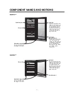
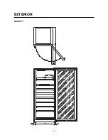
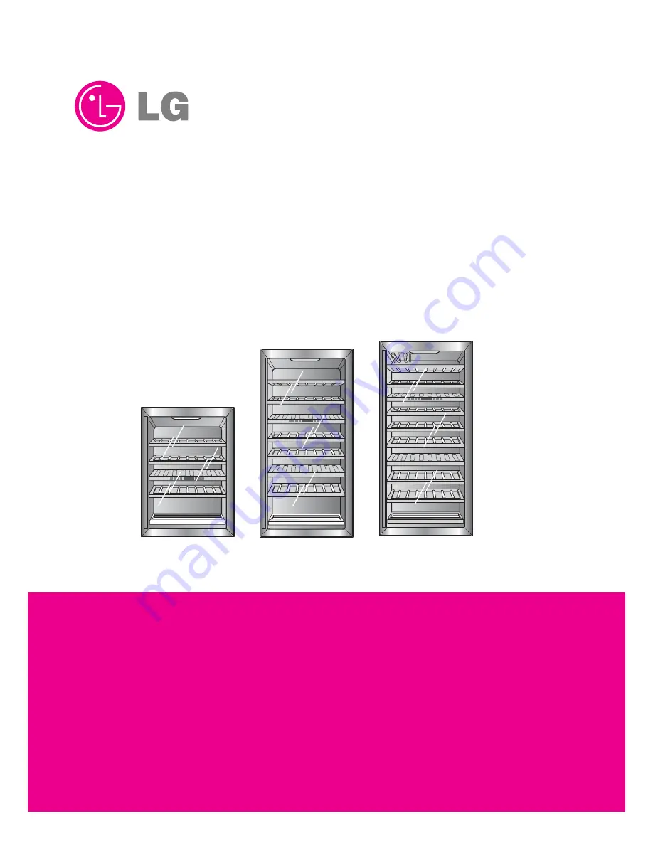
Page 8: ... 8 3 Exterior 3 1 Exterior GC W061 EXTERIOR ...

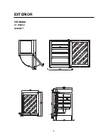
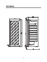
Page 9: ...GC W101 EXTERIOR 9 ...

Page 10: ...EXTERIOR 10 ...

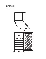
Page 11: ...GC W141 EXTERIOR 11 ...

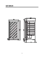
Page 12: ...EXTERIOR 12 ...

Page 13: ...out please wait at least 5 minutes before you plug it back in If you plug the power right back in it will cause a malfunction in the cooling machine MODEL GC W061 Power Plug Compressor Exterior Temperature Sensor Interior Temperature Sensor Top Cooling Sensor Top Heater Top Heater Bottom Case Display Interior Light Control Panel BK BLACK BL BLUE BO BROWN OAK BN BROWN YL YELLOW PR PURPLE GY GRAY WH...

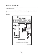
Page 14: ...CIRCUIT DIAGRAM 14 GC W101 GC W141 ...

Page 15: ... voltage Rating voltage 10 Advice the customer to use in the specified range If not 0 or Advice the customer to use in the specified range Measure minimum starting voltage after checking steps 1 3 above Measure the pressure balance of the PTC at the interval of more than 5 min Starts at the voltage of more than 90 Replace OLP Normal Normal Replace the PTC Replace the PTC STARTER The applied voltag...

Page 16: ...n the PTC with a multitester or Wheatstone Bridge Observation value is 220 240V 50Hz The value is 0 The value is Check another electric components Replace the PTC Normal Abnormal Abnormal Replace the PTC Separate the OLP from the Compressor and check resistance value between two terminals of OLP with Tester Check other electric components Replace OLP ...

Page 17: ... than 30 min Poor contacting point Shorted or Broken Coil shorted Low voltage Increase the voltage Replace the device Repair the Compressor Shorted Poor contacting point and broken Refrigerant leaks Poor compressing Check the current flowing of starting system Check the components on the main circuit Check if the current flows at the contacting point of the Thermostat Check if the current flows at...

Page 18: ...enerally to be looked for at the soldering points connecting the various components or in an eventual hole in the evaporator made by the user If in the refrigerant system a quantity of R600a is introduced which is greater than that indicated the excess gas does not terminate its expansion in the evaporator but proceeds into the return tube The refrigerant system is humid when there is a small perc...

Page 19: ...dity damages to it VACUUM 1 When measuring with pirant Vacuum gauge the charging M C vacuum degree is within 1 Torr 2 If the vacuum degree of the cycle inside is 10 Torr below for low pressure and 20 Torr for high pressure it says no vacuum leakage state 3 Vacuum degree of vacuum pump must be 0 05 Torr below after 5 min 4 Vacuum degree must be same to the value described item 2 above for more than...

Page 20: ... 20 ASSEMBLY JAWS BOLT TOOL TUBE LOKRING LOKRING JOINT Figure 15 LOKRING Figure 16 LOKRING TOOL ...

Page 21: ... 1 Top temperature setting 1 With the lock off set the top storage temperature using button on the left side of the display 2 By pressing It will display in the order of 3 By pressing It will display in the order of 4 NOTE Top temperature cannot be lower than the bottom 2 Bottom temperature setting 1 With the lock off set the top storage temperature using button on the right side of the display 2 ...

Page 22: ...3 3 WAY Valve Operation Condition 1 Appropriate valve opens closes according to the each sensor temperature 2 If both top and bottom temperature is insufficient The part that is already in cooling process finishes its cooling then the other part s valve becomes opened No simultaneous cooling 3 If the cooling is not finished in given time 45min for top 30min for bottom the parts valve in cooling pr...

Page 23: ...s of test runs Includes temporary power outrage MICOM FUNCTION AND CIRCUIT DIAGRAM 23 Wine Cellar Storage Temperature Spring Summer Fall Winter Seasons Exterior Temperature Counter Operation Normal Operation Function Load Operation Order At an initial Power on Recovering from the TEST MODE Instantly 0 5seconds 3seconds 3seconds 3seconds 3seconds 3minutes 7minutes 3minutes 10seconds Top Heater OFF ...

Page 24: ...ter 2 hours 3 After you terminate the test mode you have to unplug the power in order to resume the normal mode MICOM FUNCTION AND CIRCUIT DIAGRAM 24 1 2 3 4 5 6 NO Malfunctions Conditions A part B part C part D part E part Top sensor malfunction Top EVA sensor malfunction Bottom sensor malfunction BottomEVAsensormalfunction Exterior sensor malfunction Communication malfunction 8 E 8 8 8 OFF E 8 8...

Page 25: ...on Circuit Synchronizing CLOCK generation for transmitting and receiving information of IC1 MICOM inner logic devices and time generation for time calculation If specifications of OSC1 are modified it may alter its calculation time or may cause a malfunction Please use regular parts 6 2 3 RESET Circuit When MICOM is powering up from an initial power on or from a power outrage recovery the reset ci...

Page 26: ...H and LOW signals through MICOM PIN 16 15 18 and 17 Revolving magnetism forms on the motor coil Motor starts running MICOM FUNCTION AND CIRCUIT DIAGRAM 26 Load Type COMP Top Maturing Heater Bottom Maturing Heater MeasuringParts IC2 15 13 14 Condition ON Below 1V OFF 12V CON6 IC6 R14 R15 R16 R17 16 R41 P40 P43 P42 15 18 17 ...

Page 27: ...ntrolling top bottom parts storage maturing temperature and an exterior temperature sensor Each sensor s SHORT and OPEN condition is as followed MICOM FUNCTION AND CIRCUIT DIAGRAM 27 P11 20 R18 Sensor Check Point Normal 30 50 SHORT OPEN Exterior Sensor POINT A Voltage Top Sensor POINT B Voltage Bottom Sensor POINT E Voltage 0 5 V 4 5 V 0 V 5 V Top EVA Sensor POINT C Voltage Bottom EVA Sensor POINT...

Page 28: ...3 1 Decrease 0 5 Decrease NoChange 0 5 Increase 1 Increase 1 5 Increase 2 Increase 2 5 Increase 3 Increase 3 5 Increase 4 Increase 5 6 1 5 Decrease 1 Decrease 0 5 Decrease NoChange 0 5 Increase 1 Increase 1 5 Increase 2 Increase 2 5 Increase 3 Increase 3 5 Increase 8 2 2 Decrease 1 5 Decrease 1 Decrease 0 5 Decrease NoChange 0 5 Increase 1 Increase 1 5 Increase 2 Increase 2 5 Increase 3 Increase 1...

Page 29: ...OM and DISPLAY PCB in MAIN PCB If there is an interruption in information exchange between MAIN MICOM and DISPLAY PCB in MAIN PCB for more than 30 seconds it causes a communication malfunction MICOM FUNCTION AND CIRCUIT DIAGRAM 29 DISPLAYPCB MAIN PCB MAIN MICOM DC 12V GND Transmitting Error Receiving NOTCH LCD Controlling MICOM ...

Page 30: ...tester has greater error range 4 For sensor measurement separate MAIN Part CON4 HOUSING in PWB PCB ASSEMBLY Referring to a circuit diagram above measure each sensor s terminal at a separated housing MICOM FUNCTION AND CIRCUIT DIAGRAM 30 Temperature Top Bottom Sensor Top Bottom EVA Sensor Measurement Exterior Sensor 20 77 15 60 10 47 3 5 38 4 0 30 5 24 1 10 19 5 15 15 9 20 13 25 11 30 8 9 40 6 2 50...

Page 31: ...6 4 MAIN PWB ASSEMBLY AND PARTS LIST 6 4 1 MAIN PWB ASSEMBLY MICOM FUNCTION AND CIRCUIT DIAGRAM 31 ...

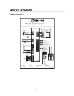
Page 32: ...6 4 2 Replacement Parts List MICOM FUNCTION AND CIRCUIT DIAGRAM 32 ...

Page 33: ...6 4 3 PWB ASS Y DISPLAY AND PARTS LIST MICOM FUNCTION AND CIRCUIT DIAGRAM 33 ...

Page 34: ...6 5 PWB DIAGRAM 6 5 1 PWB Assembly Main DIAGRAM PWB circuit diagram may vary a little bit depending on actual condition MICOM FUNCTION AND CIRCUIT DIAGRAM 34 ...

Page 35: ...MICOM FUNCTION AND CIRCUIT DIAGRAM 35 ...

Page 36: ...6 5 2 PWB Assembly DISPLAY DIAGRAM PWB circuit diagram may vary a little bit depending on actual condition MICOM FUNCTION AND CIRCUIT DIAGRAM 36 ...

Page 37: ... reflection and 20 of ultraviolet rays transmission The glass can be reinforced preventing any injury from an exterior impact Also the heat resistant quality of ITO glass prevents any frost forming 7 3 Low vibration Anti vibration structure Vibration causes convection in precipitations on the bottom of the wine bottle resulting in a wine heat up by an over aging Low vibration Anti vibration struct...

Page 38: ...ut Sensor malfunction Cut wire or a short circuit in the exterior sensor Solution Replace Valve Switch valve terminal location Replace Case display Replace barrier Replace Case display Replace Case display Replace barrier Product Exchange Symptom Condition Over cooling and weak cooling in upper and lower part at the same time Insufficient cooling in upper and lower part Operation malfunction and O...

Page 39: ... radiation area Install the product in a dry and well ventilated space It may form a mold resulting in a high electric bill 9 2 Cleaning Instruction Before cleaning make sure that the power is unplugged and clean the wine shelf the interior once a year 1 Unplug the power 2 Please use a soft cloth dampened with water or a detergent for exterior If you are using a neutral detergent wash it off with ...

Page 40: ...NTENANCE 40 햲 Press Hold button for 3 seconds In the unlocked state the temperature indicators blink Children should be restricted from tampering with the Hold button to avoid causing unwanted changes 햳 Each press of an upper or lower temperature button will raise or lower the temperature by 1 C 햴 After the temperature is set press the Hold utton again The indicator will be on showing the temperat...

Page 41: ...hen you take out the bottle It may also cause damage to the shelf 9 4 2 Long term storage GC W141 For a leftover wine store it with its lid tightly shut Precipitations may form on the bottom of the wine bottle according to wine variety storage condition and storage length This is only natural 9 4 3 Bottom shelf storage Bottom shelf can hold 4 bottles maximum 9 bottles MAINTENANCE 41 BOTTOM SHELF 4...

Page 42: ...f the gasket 1 Be careful not to tear the gasket when separating the part 2 It is much easier if you pull the corner of the gasket 10 3 Separate the handle and the bar 1 Take out 3 screws on the bottom of the handle 2 Take out 3 screws on the top of the handle 10 4 Separate the supporter and the handle U L 1 Use the rubber handle for supporter and handle U L separation 10 5 Reverse the order for a...

Page 43: ...6B B 1 13 36 6B B 1 13 36 6B B 5 50 03 3B B 1 13 36 6B B 2 23 33 3A A 2 24 44 4A A 2 24 44 4E E 2 24 44 4E E 2 23 30 0A A 1 13 36 6A A 1 13 36 6C C 3 31 19 9C C 3 31 15 5A A 4 40 09 9B B 11 10 0C C 3 31 17 7A A 3 3 1 18 8A A 3 30 08 8A A 3 30 09 9A A 1 12 20 0D D 3 31 12 2A A 3 31 14 4A A 3 31 10 0A A 5 50 01 1 K K 5 50 01 1F F 3 30 05 5A A 4 40 09 9B C 2 24 43 3A A 1 609H 120D 1 503F 316A 327A 31...

Page 44: ...2 28 81 1E E 1 10 06 6B B 1 128C 1 145D 1 128D 2 23 33 3A A 2 24 44 4E E 2 23 30 0A A 2 24 44 4A A 2 24 44 4E E 1 13 36 6A A 5 50 03 3B B 1 149B B 1 14 4 9 9 B B 1 14 49 9B B 1 13 36 6C C 1 15 55 5D D 2 28 81 1A A 2 28 81 1B B 1 12 20 0D D 4 40 09 9B C 1 10 06 6A A 2 28 83 3B B 2 28 83 3D D 1 10 06 6A A 2 24 43 3A A 4 40 09 9B B 11 10 0C C 120D 4 40 09 9B B 120D 1 609H 503F 316A 327A 316B 328B 5 5...

Page 45: ... 3PREAD SHEET 7 3 26 0 243 24 1 1 ...

Page 46: ...P No 3828JS8026C JULY 2005 Printed in China ...

Reviews: