LG FB162I, Service Manual
The LG FB162I service manual is a comprehensive guide that provides detailed instructions on how to operate and maintain this exceptional product. Easily download this user manual for free from manualshive.com, enabling you to make the most out of your LG FB162I audio system.
Share
Download


Reviews:
No comments
Related manuals for FB162I
8000 Series
Brand: KEF Pages: 13
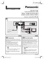
SC-HTE180
Brand: Panasonic Pages: 2
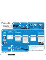
VieraLink SC-ALL30T
Brand: Panasonic Pages: 12
SC-HTB550
Brand: Panasonic Pages: 36
SC-HTB570
Brand: Panasonic Pages: 2
SC-BT205
Brand: Panasonic Pages: 2
SC-HTB20
Brand: Panasonic Pages: 2
SCBT730 - BLU RAY HOME THEATER SYSTEM
Brand: Panasonic Pages: 2

SC-ALL70T
Brand: Panasonic Pages: 12
SC-HTB15
Brand: Panasonic Pages: 32
SC-HTB8
Brand: Panasonic Pages: 24
SC-HTB20
Brand: Panasonic Pages: 32
SC-HTB400
Brand: Panasonic Pages: 32
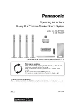
SC-BTT500W
Brand: Panasonic Pages: 52
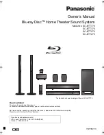
SC-BTT270
Brand: Panasonic Pages: 52
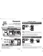
SC-HTB880
Brand: Panasonic Pages: 2
SC-HTB770
Brand: Panasonic Pages: 44
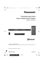
SC-HTE80
Brand: Panasonic Pages: 36


