LG CT-21Q41KE, Service Manual
The LG CT-21Q41KE is a high-quality television that offers exceptional performance and stunning visuals. To enhance your user experience, our website offers a comprehensive and user-friendly Service Manual for free download. Simply visit manualshive.com to obtain this valuable manual and unlock the full potential of your LG CT-21Q41KE.
Share
Download


Reviews:
No comments
Related manuals for CT-21Q41KE

L32K1
Brand: Haier Pages: 54

HL15R - 15" LCD TV
Brand: Haier Pages: 26
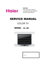
HL15R - 15" LCD TV
Brand: Haier Pages: 61
HL22F1 - Designer F-Series - 22" LCD TV
Brand: Haier Pages: 49
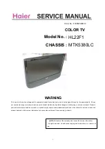
HL22F1 - Designer F-Series - 22" LCD TV
Brand: Haier Pages: 50
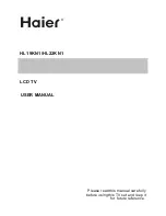
HL22KN1
Brand: Haier Pages: 26
HL22KN1
Brand: Haier Pages: 56
HL32K
Brand: Haier Pages: 54
HL37B - 37" LCD TV
Brand: Haier Pages: 45
HL37B - 37" LCD TV
Brand: Haier Pages: 49
HL47E - 47" LCD TV
Brand: Haier Pages: 50
HL47E - 47" LCD TV
Brand: Haier Pages: 50

HLC15R - 15" LCD TV
Brand: Haier Pages: 62
HLC15T
Brand: Haier Pages: 55
HLC19E
Brand: Haier Pages: 43
HLC19E
Brand: Haier Pages: 36
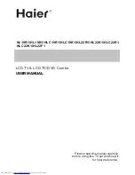
HLC19KW1 - K-Series - 19" LCD TV
Brand: Haier Pages: 50
HLC22K1 - K-Series - 22" LCD TV
Brand: Haier Pages: 50


