LG ARNU48GBRZ4, Engineering Product Data Book
The LG ARNU48GBRZ4 is a top-of-the-line air conditioning unit designed for optimal performance and energy efficiency. Ensure a hassle-free installation by downloading its comprehensive Installation Manual for free from our website. This manual provides step-by-step instructions and valuable insights to make setup easier and more convenient.
Share
Download


Reviews:
No comments
Related manuals for ARNU48GBRZ4

575
Brand: Dapper Lighting Pages: 2

2020
Brand: Accel Pages: 2

Titanium Series
Brand: Fass Pages: 13

Raptor
Brand: Yamaha Pages: 2

Porsche 911 Turbo S Wheel
Brand: FANATEC Pages: 9

2008 Liberty
Brand: Jeep Pages: 6

Yamaha Rhino 660
Brand: Yamaha Pages: 3

10-8002-C11998B
Brand: Saleen Pages: 12

WingMan
Brand: Code 3 Pages: 8

For 1985-1992 GM Cars and Trucks 17933
Brand: Edelbrock Pages: 4

6883
Brand: Edelbrock Pages: 2

AX-AM-AU92
Brand: Axxess Pages: 8

66002
Brand: Edelbrock Pages: 2

Chevrolet 5783
Brand: Edelbrock Pages: 1

EM-2201
Brand: Audiovox Pages: 1
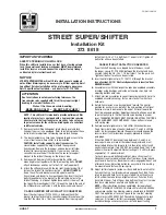
STREET SUPER SHIFTER
Brand: HURST Pages: 2

Ride-Rite Air Helper Springs 2173
Brand: Firestone Pages: 4

65932
Brand: Edelbrock Pages: 2


