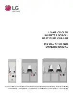
background image

INSTALLATION AND 

OWNERS MANUAL

LG AIR-COOLED  

INVERTER SCROLL

 HEAT PUMP CHILLER 

ACHH017VBAB, ACHH020VBAB, ACHH033VBAB, ACHH050VBAB, ACHH060VBAB:   208-230V/60Hz/3PH

ACHH017HBAB, ACHH020HBAB, ACHH033HBAB, ACHH050HBAB, ACHH060HBAB:  460V/60Hz/3PH

Summary of Contents for ACHH017HBAB

Page 1: ...ND OWNERS MANUAL LG AIR COOLED INVERTER SCROLL HEAT PUMP CHILLER ACHH017VBAB ACHH020VBAB ACHH033VBAB ACHH050VBAB ACHH060VBAB 208 230V 60Hz 3PH ACHH017HBAB ACHH020HBAB ACHH033HBAB ACHH050HBAB ACHH060HBAB 460V 60Hz 3PH ...

Page 2: ...reference Content familiarity is required for proper installation The instructions included in this manual must be followed to prevent product malfunction property damage injury or death to the user or other people Incorrect operation due to ignoring any instructions will cause harm or damage The level of seriousness is classified by the symbols described by the summary list of safety precautions ...

Page 3: ...ices and Settings 25 Installation to Test Run Flowchart 26 Placement Considerations 27 Transporting Lifting 32 Storing the Chiller Installing Anti Vibration 33 Water Pipe System Piping 35 Freezing Precautions 38 Water Pipe Installation Pump Control Quality Management 39 Operating Pressure Drop Design Flow 40 Control Panel Configuration 41 Button Locations and Functions 42 Optional Settings 43 Elec...

Page 4: ...perate improperly or parts other than those specified by LG are used there is risk of fire electric shock explosion and physical injury or death Replace all control box and panel covers If cover panels are not securely installed dust water and animals will enter the outdoor unit causing fire electric shock and physical injury or death Always check for system refrigerant leaks after the unit has be...

Page 5: ...eration malfunction Properly install and insulate the drain piping to ensure water is drained away properly Improper installation can cause water to leak causing a slippery surface condition and or water damage Always check for system refrigerant leaks after the unit has been installed or serviced Low refrigerant levels will cause product failure Do not make refrigerant substitutions Use only the ...

Page 6: ...tion devices If the protection devices have been bypassed or is forced to operate improperly or parts other than those specified by LG are used there is risk of fire electric shock explosion and physical injury or death WIRING High voltage electricity is required to operate chiller Adhere to the U S National Electric Codes NEC and these instruc tions when wiring Improper connections and inadequate...

Page 7: ... or flammable gases Using these substances will cause fire explosion and physical injury or death If refrigerant leaks ventilate the area before operating the unit If the chiller is mounted in an enclosed low lying or poorly ventilated area and it develops a refrigerant leak it will cause a fire electric shock explosion physical injury or death To avoid physical injury use caution when cleaning or...

Page 8: ...rk of LG Corp UNIT NOMENCLATURE AC H 020 H B A Evaporator A Direct Exchange Type DX Type Plate Power Specifications H 460V 60 Hz 3Ø B 208 230V 60 Hz 3Ø Capacity RT 017 17RT 040 40 RT 020 20 RT 050 50 RT 033 33 RT 060 60 RT Compressor Type H High Pressure Scroll Cooling Type A Air Cooled Cooling Only W Water Cooled Cooling Only H Air Cooled Heat Pump K Water Cooled Heat Pump Family AC R410A Chiller...

Page 9: ...ssure discharge area and the motor is installed on the low pressure vapor area Space for the motor and storage for refrigerant is secured in the low pressure vapor area to increase liquid compression reliability Because the suction refrigerant vapor cools the motor and flows to the compressor a separate device to cool the compressor is not required Inside the system oil to lubricate the compressor...

Page 10: ... chart and in the following chart shows the conditions of the refrigerant The refrigerant comes into the compressor motor and cools the motor and becomes overheated and moves to the internal suction inlet section of the compres sor The oil inside the compressor seals the gap between the compressor scrolls and provides lubrication for the bearing to help the compression of the refrigerant During th...

Page 11: ... 3 1 2 7 3 1 Opera ng Maximum Pressure Refrigerant Water psi 597 142 597 142 597 142 597 142 Cooling Water Flow 10F Delta GPM 38 9 44 4 77 8 88 7 Inlet Outlet Water Connec on inches flange 2 150 lb 2 150lb 2 1 2 150lb 2 1 2 150lb No of Fan Motors EA 2 2 4 4 No of Blades per Fan EA 6 6 6 6 Air Flow Rate CFM 8684 8684 8684 8684 Motor Power W 900 900 900 900 Metering lbs 1162 1162 2218 2218 W inches 3...

Page 12: ...684 8684 Motor Power W 900 900 Metering lbs 3208 3208 W inches 90 13 16 90 13 16 H inches 86 5 8 86 5 8 D inches 84 13 16 84 13 16 2 RT 1 09 0 96 High Low Pressure Electronic Flow Switch Paddle ADJ Freeze Protec on On Off Contact Only Type Cooling F Hea ng F Approved Water Delta T Cooling and Hea ng F Cooling F Hea ng F 1 Due to our policy innovations some specification may be changed without prior...

Page 13: ... psi 2 7 3 1 2 7 3 1 Opera ng Maximum Pressure Refrigerant Water psi 597 142 597 142 597 142 597 142 Cooling Water Flow 10F Delta GPM 38 9 44 4 77 8 88 7 Inlet Outlet Water Connec on inches flange 2 150 lb 2 150lb 2 1 2 150lb 2 1 2 150lb No of Fan Motors EA 2 2 4 4 No of Blades per Fan EA 4 4 4 4 Air Flow Rate CFM EA 8684 8684 8684 8684 Motor Power W EA 1500 1500 1500 1500 Metering lbs 1162 1162 22...

Page 14: ...6 6 Air Flow Rate CFM EA 8684 8684 Motor Power W 1500 1500 Metering lbs 3208 3208 W inches 90 13 16 90 13 16 H inches 86 5 8 86 5 8 D inches 84 13 16 84 13 16 2 RT 1 09 0 96 High Low Pressure Electronic Flow Switch Paddle ADJ Freeze Protec on On Off Contact Only Type Cooling F Hea ng F Approved Water Delta T Cooling and Hea ng F Cooling F Hea ng F Guaranteed Load Capacity Range 20 100 Remote Monito...

Page 15: ...0 9 7 40 8 1 33 ACHH033HBAB 460 60 3 414 506 88 6 100 19 5 79 6 1 40 ACHH040HBAB 460 60 3 414 506 90 8 100 19 5 81 6 1 50 ACHH050HBAB 460 60 3 414 506 130 4 150 29 2 119 4 1 60 ACHH060HBAB 460 60 3 414 506 133 6 150 29 2 122 4 1 Table 3 Electrical Data for Single 460V 3 Wire Cooling Only Chiller Voltage Range Power supplied to the chiller must fall within the voltage minimum to maximum range liste...

Page 16: ...Electronics U S A Inc Englewood Cliffs NJ All rights reserved LG is a registered trademark of LG Corp DIMENSIONS Figure 4 Dimensions for Single Frame Chiller ACHH017VBAB ACHH017HBAB ACHH020VBAB ACHH020HBAB D B C A E F G Water Outlet Flanged 2 inches 150lb Water Inlet Flanged 2 inches 150lb Front Back Side Unit Inch Label Dimensions 30 1 8 86 17 32 86 5 8 84 13 16 19 31 32 27 9 16 15 1 8 ...

Page 17: ... reserved LG is a registered trademark of LG Corp DIMENSIONS Figure 5 Dimensions for Double Frame Chiller ACHH033VBAB ACHH033HBAB ACHH040VBAB ACHH040HBAB Water Inlet Flanged 2 1 2in 150 lb D B A F E G C Front view Rear view Side view Unit inch Classification Dimension A 60 3 16 B 86 17 32 C 86 5 8 D 84 13 16 E 19 31 32 F 27 9 16 G 15 1 8 Water Outlet Flanged 2 1 2in 150 lb ...

Page 18: ...Inc Englewood Cliffs NJ All rights reserved LG is a registered trademark of LG Corp DIMENSIONS Figure 6 Dimensions for Triple Frame Chiller ACHH050VBAB ACHH050HBAB ACHH060VBAB ACHH040HBAB D B A F E G C Front view Rear view Side view Unit inch Classification Dimension A 90 1 4 B 86 17 32 C 86 5 8 D 84 13 16 E 19 31 32 F 27 9 16 G 15 1 8 Water Inlet Flanged 2 1 2in 150 lb Water Outlet Flanged 2 1 2i...

Page 19: ...red trademark of LG Corp REFRIGERANT PIPING AND SENSOR DIAGRAM OPERATION RANGE AND LIMIT Figure 7 Single Frame Chiller Refrigerant Piping and Sensor Location Diagram Refrigerant Piping and Sensor Diagram Single Frame M S Cooling Heating Fan motor 4 way valve Pressure sensor Pressure switch Solenoid valve Check valve Strainer Electonic expantion Valve Expansion valve Temperature sensor Compressor 2...

Page 20: ...ghts reserved LG is a registered trademark of LG Corp Figure 8 Dual Frame Chiller Refrigerant Piping and Sensor Location Diagram Refrigerant Piping and Sensor Diagram Dual Frame M S Cooling Heating Fan motor 4 way valve Pressure sensor Pressure switch Solenoid valve Check valve Strainer Electonic expantion Valve Expansion valve Temperature sensor Compressor 2 Compressor 2 REFRIGERANT PIPING AND SE...

Page 21: ... of LG Corp REFRIGERANT PIPING AND SENSOR DIAGRAM OPERATION RANGE AND LIMIT Figure 9 Tri le Frame Chiller Refrigerant Piping and Sensor Location Diagram Refrigerant Piping and Sensor Diagram Triple Frame Compressor 2 Compressor 2 Compressor 2 M S Cooling Heating Fan motor 4 way valve Pressure sensor Pressure switch Solenoid valve Check valve Strainer Electonic expantion Valve Expansion valve Tempe...

Page 22: ...eration Limit Recommendation for 208 230V is 120 F 4 LG LATS ISC Selection Software is to be used to confirm selection and performance 68 F LWT 100 to 65 44 F LWT 100 to 50 14 F LWT 77 to 33 45 35 25 105 95 85 75 65 125 Ambient Air Degrees F 45 55 65 75 85 95 25 35 EWT and LWT Chilled Water Temperature Degrees F ACHH Chilled Water Operation Limits and Performance Cold Water Inlet Temperature F Col...

Page 23: ... and performance 86 F LWT 22F 30 17F 100 105 F LWT 4F 65 32F 100 120 F LWT 14F 70 32F 100 131 F LWT 17F 70 41F 100 of Rated Capacity 105 95 85 ACHH Hot Water Operation Limits and Performance 145 135 125 115 30 40 50 60 75 65 55 20 10 0 Approved Δ between EWT and LWT is 4 F to 20 F Heating Capacity Performance 10 ΔT EWT to LWT 100 90 70 80 90 100 Ambient Air Degrees F Operation Range HOT Water Inle...

Page 24: ... for the specific conditions 2 The 40 Ton ACHH040 BAB will provide 2X the capacity at the same conditions 3 The 60 Ton ACHH060 BAB will provide 3X the capacity at the same conditions 4 LATS ISC is a dynamic selection tool provided in support of the LG ACHH Series Inverter Scroll Heat Pump Chiller Please refer to LATS for final and specific performance data 5 The chart above is intended only to be ...

Page 25: ...sures and stops over current per motor 5 Discharge tem perature sensor 230 F Stops compressor in stages 6 High pressure sensor 551 PSI Starts protective operation control to reduce the cycle pressure 7 Low pressure sensor 32 PSI Starts protective operation control to raise the cycle pressure 8 Water pipe tem perature sensor Prevent evaporator from freezing Not active if low temperature cooling is ...

Page 26: ...llation and Owners Manual Start Delivery and Installation Test Operation Instruction and installation of base following IOM and all applicable codes Delivery and Installation Wiring and Piping Set Control Address Check before Initial Start Check During and After Initial Start Stop Load Operation and Operation Adjustment Prepare Operation Data Analyze Water Quality Guide Operation End INSTALLATION ...

Page 27: ... a fence or barricade around the chiller to prevent animals and or unauthorized individuals from accessing it Install a boundary or danger sign if necessary Damage to the components could cause fire explosion physical injury or death Do s Select a location for installing the chiller that meets the following conditions Where it is flat and there is enough strength to support the weight of and vibra...

Page 28: ...ect a location with good drainage If the chiller is installed in an area where it would be directly exposed to ocean winds additional anti corrosion treatment will need to be applied to the chiller condenser Ocean winds will cause corrosion particularly on the condenser which in turn could cause product malfunction or inefficient performance If the chiller must be placed in a location where it wou...

Page 29: ...ing the clearance space between the top of the chiller and the ceiling must be a minimum of 197 inches If the front or back of the chiller is near a wall the clearance space between the chiller and the wall must be a minimum of 32 inches Ventilation Clearance Requirements Air cooled chillers must be installed in an open space or must have appropriate ventilation If the chiller must be installed ne...

Page 30: ...re 20 Service Clearance Requirements for One Chiller Figure 21 Service Clearance Requirements for Two Chillers Service Space Min 36 Min 71 Min 32 Min 32 Unit Inches Location where the water pipes are installed Ensure that there is sufficient clearance space for future service mainte nance and repair Min 71 Min 36 Min 32 Min 32 Min 24 Service Space Unit Inches Location where the water pipes are ins...

Page 31: ...snow has accumulated on top of the chiller remove the snow and then operate the unit 5 The base or pad size is to be larger than the chiller Follow local and state requirement for final design 6 Do not install the chiller in an area where heavy snow accumulation could negatively impact chiller operation Position the chiller in such a way that the side with the air heat exchanger does not face the ...

Page 32: ... and dispose the plastic vinyl r packaging so that children do not play and risk suffocation and death Lift and support the chiller at specified locations at least four 4 points to avoid slipping from the rigging apparatus and the appropriate length 26 1 feet 8 7 yd and number of lifting straps There is a risk of the product falling and causing physical injury Use caution when using forklift to tr...

Page 33: ...nd resolve any issues before installing the chiller Install the chiller so that it will not fall over due to strong winds or earthquakes If installing the chiller in a coastal area where it is impacted by ocean winds additional anti corrosive treatment must be applied to the condenser If combining multiple chillers it is best to ensure all are at the same level so that the water pipes can be easil...

Page 34: ...om of the chiller must be removed before installation and tightening the anchor bolts Use anchor bolts to firmly attach the chiller to the installation area base Tighten the bolts so that the chiller does not fall over from strong winds or earthquakes Must be engineered by local professional Noise and operation vibration from the chiller can be transferred to the floor or wall of the installation ...

Page 35: ...ld design the loop capacity A common minimum loop design is 2 times the GPM of a 10 degree delta or standard rated GPM for the system Pipe Slope and Air Vent Valve If air remains in the water pipes water pipe system resistance increases and or the amount of circulating water is reduced significantly If air remains in the pump during operation it can result in chiller malfunction or shutdown Instal...

Page 36: ...lation Method A Recommended Independent product installation LG Supplied P1 T1 T2 P2 LG Supplied P2 T2 P1 T1 Leaving Water Entering Water Symbol Description Symbol Description Provided by Others Valve 100 Flow T1 or T2 Temperature Sensor 1 Inlet 2 Outlet Strainer 50 Mesh P1 or P2 Pressure Gauge 1 Inlet 2 Outlet Flexible Joint Water Pump Pump Sized to Meet Minimum to Maximum Flow for LG Chiller Ser...

Page 37: ... P2 T2 P1 T1 LG Supplied Leaving Water Entering Water Installation Method B Independent product installation Figure 29 Installation Method B Symbol Description Symbol Description Provided by Others Valve 100 Flow T1 or T2 Temperature Sensor 1 Inlet 2 Outlet Strainer 50 Mesh P1 or P2 Pressure Gauge 1 Inlet 2 Outlet Flexible Joint Water Pump Pump Sized to Meet Minimum to Maximum Flow for LG Chiller ...

Page 38: ...n drain the circulation water out of the system Add anti freeze to prevent the circulation water from freezing during the winter season if design temperature is below 41 F Maintain water flow following design specifications to reduce damage from rusting scaling and corrosion LG is not responsible for any chiller damage resulting from poor water quality management or improper water processes Inlet ...

Page 39: ...er than that of the chiller When multiple chillers are manifolded together piping is to be properly sized and engineered by a licensed professional To prevent the water pipe connections from sagging due to the load install appropriate pipe supports Position the water inlet pipe at the bottom of the water pipe system and position the outlet pipe at the top of the water pipe system If there is a ris...

Page 40: ...105 200 210 300 315 Model Number Operating Maximum Pressure psi Min Flow GPM Rated Flow GPM Max Flow GPM ACHH017 BAB ACHH020 BAB Refrigerant 597 Water 142 19 24 38 48 57 72 ACHH033 BAB ACHH040 BAB 60 Pressure Drop ftAq 18 17 16 15 14 13 12 4 11 8 10 9 7 6 3 2 20 40 50 70 80 170 180 190 130 140 150 160 90 100 110 120 120 130 140 320 330 330 220 230 200 210 20 40 50 60 70 80 290 300 310 240 250 260 ...

Page 41: ...ng and commands displays product information and information for each cycle Main Controller Controls the input output port and communicates with each cycle Power Supply Supplies power to the HMI MCCB Molded Case Circuit Breaker MCCB Shuts off the overcurrent Line or High Voltage Terminal Block The terminal block that receives the external main power Main Controller x o B l o r t n o C n i a M x o ...

Page 42: ...nd Owners Manual BUTTON LOCATIONS AND FUNCTIONS Switch location Chiller Controller includes the buttons described above so that the following functions are avail able for setting without HMI SW_COMF SW_LEFT SW_UP SW_BACK SW_RIGHT SW_DOWN Name Description SW_RIGHT Changes the setting SW_UP Moves the screen SW_LEFT Changes the setting SW_DOWN Moves the screen SW_COMF Sets the selected function SW_BA...

Page 43: ... Left or Right Buttons to go to a desired function And Press SW_COMF Button to set the function To go to the previous press SW_BACK Button Screen Button Description Screen Displays 0 Level Screen Displays 1 Level 1 Start Stop O P E R R U N S T O P 2 Cooling Heating C Y C L H E A T C O O L 7 E T C e r u t a r e p m e t t n i o p t e s g n i l o o C 3 4 Heating setpoint temperature H T E 4 5 5 Load ...

Page 44: ... Level Control Mode LOC DIST SCHE Set s the product s Control Mode In LOC the product control is available with HMI and Chiller Controller DIST refers Remote Control Mode In SCHE the prod uct is controlled following the schedule set at HMI Remote Mode CONT BUS Sets how to set in Remote Mode CONT enables the product s operation mode by simple switch contacts BUS enables the control on the entire pr...

Page 45: ...ach other HMI communication error will occur Main Controller address setting Press down direction and right direction button at the same time When FN01 appears press SW_CONF button Select desired address using left and right button and address will be set if press SW_CONF button If you don t want please press SW_CONF button Description Screen Displays 0 Lever Screen Displays 1 Lever 1 Chiller Addr...

Page 46: ...uaranteed communication distance of HMI 500 m But when connected indoor the end resistance 100 200 Ω must be installed at the termi nal connected to HMI for smooth communication In this case if the installation location of the Unit is different from that of HMI the maximum permitted connection distance of the communication cable between the two locations is displayed Logging in to HMI This chapter...

Page 47: ...screen that shows the common information of the product is displayed as shown below HMI main screen configuration Icon Description You can see the load water temperature pump flow amount status and sys tem information It sets the Start Stop Set Temperature Operation Mode Only for Heatpump Model control mode max operation frequency and demand control ratio are set It checks the individual cycle s op...

Page 48: ...G Corp LG Air Cooled Heat Pump Inverter Scroll Chiller Installation and Owners Manual HMI SCREENS Chiller information is composed of the load water temperature pump flow amount status and system information Load water temperature screen Icon Description E W T It shows the common load entering water temperature value L W T It shows the common load leaving water temperature value View chiller inform...

Page 49: ...erature 5 C 2 min operation and 18 min stop Outdoor air temperature 5 C operation OFF The freeze and burst prevention mode is possible when the pump is connected and to interface with the pump Pump Output connect shall be connected and to check whether the pump operates Pump Interlock connector shall be connected For the connector connection method refer to the connection diagram Pump Interlock It...

Page 50: ... Heat Pump Inverter Scroll Chiller Installation and Owners Manual HMI SCREENS System information screen Icon Description Setting Temp It shows the set temperature for the current operation mode Outdoor Temp It shows the current outdoor air temperature value Operation Current It shows the operation compressor s overall operation current value Starting Delay It shows the time of the standby state be...

Page 51: ...mand of the product It sets the target temperature value for the current operation mode Cooling 4 0 20 0 C heating 30 0 55 0 C It sets the cooling heating operation mode It selects the control mode of the signal command method for the product control Max Operating Frequency is the feature to save the energy by limiting the operation capacity up to the frequency set by the user Setting Range 70Hz 1...

Page 52: ...ers Manual HMI SCREENS ON OFF When you touch the ON button a popup window to select ON OFF is displayed Setting temperature If you touch the area where the chiller control s set temperature is displayed a popup window to input the setting temperature is displayed In the temperature setting popup window you can change the temperature with up down arrow input and if you touch the temperature setting...

Page 53: ... HMI SCREENS After changing the temperature setting if you press Apply the set value is reflected and if you press Cancel the previous setting is maintained Operation mode If you touch the chiller control s operation mode area a popup window to set the operation mode is displayed After changing the operation mode if you press Apply the set value is reflected and if you press Cancel the previous se...

Page 54: ... control s control mode area a popup window to set the control mode is displayed After selecting the desired control mode if you press Apply the selected control mode is applied and if you press Cancel the previous setting is maintained Icon Description Manual control mode through HMI If the schedule mode is set manual and remote control are not possible and only the start stop by the schedule is ...

Page 55: ...ers When the communication is recovered it will automatically resume If the remote modbus connection is not used reset the power of the main PCB of the unit to cancel the alarm The protocol details provided for modbus interlock of external device are as follows Physical Layer RS 485 Serial Line Mode MODBUS RTU Mode Baud Rate 9 600 Parity None Parity 1 Stop Bit Applied Function Code Refer to the mo...

Page 56: ...tting is the max operating frequency In the installer mode if you press the capacity control setting for more than 5 seconds and enter the password a pop up window for setting the capacity control type appears Select the wanted capacity control and click the Apply button If you press the cancel it keeps the previous settings Max Operating Frequency If you touch the Max Operating Frequency area a p...

Page 57: ...U S A Inc Englewood Cliffs NJ All rights reserved LG is a registered trademark of LG Corp HMI SCREENS Demand control ratio If you touch the demand control ratio a pop up window appears where you can enter the oper ation rate Demand Control ratio can be adjusted by inputting up down arrows in the demand control ratio pop up window ...

Page 58: ... Manual HMI SCREENS To enter the cycle information screen press the cycle information button in Home screen Icon Description It shows the currently selected cycle You can select the cycle information and the cycle temperature It shows the status value of the 4 way valve during the cooling heating switching It is the item that is displayed only in the cooling heating combined model Show the status ...

Page 59: ...rights reserved LG is a registered trademark of LG Corp HMI SCREENS Icon Description Show the operation current value of operation compressor Show operation time Icon Description It shows the inverter compressor s operation frequency value It shows the current EEV pulse signal value It shows the current high pressure value It shows the current low pressure value ...

Page 60: ...d LG is a registered trademark of LG Corp LG Air Cooled Heat Pump Inverter Scroll Chiller Installation and Owners Manual HMI SCREENS Cycle temperature Icon Description Show individual outlet temperature value of the cycle Show individual inlet temperature value of the cycle Show condensation temperature value of the cycle Show Evaporation temperature value of the cycle ...

Page 61: ...nics U S A Inc Englewood Cliffs NJ All rights reserved LG is a registered trademark of LG Corp HMI SCREENS Icon Description Show compressor discharge temperature value of the cycle Show compressor discharge temperature value of the cycle Show HEX temperature value of the cycle Show liquid line temperature value of the cycle ...

Page 62: ...wners Manual HMI SCREENS Introduction to schedule menu This chapter describes the schedule menu and screen composition that you need to know to operate the schedule of the product In Home screen if you press the schedule icon the schedule screen appears k e e W h t n o M List Icon Description You can check the monthly set schedule at a glance You can check the start time of the schedule and the se...

Page 63: ...egistered trademark of LG Corp HMI SCREENS Add schedule 1 In the schedule viewing screen press button at the top right side 2 As follows when Add screen appears input the basic schedule information When you press the name area a popup window to input the schedule name is displayed Input the name to use and press Apply button If Cancel button is pressed the previous set ting is maintained ...

Page 64: ...the start date and end date to use the schedule operation and press Apply button If Cancel button is pressed the previous setting is maintained When you press the time area a popup window to set the time is displayed Set the time to use the schedule operation and press Apply button If Cancel button is pressed the previ ous setting is maintained When you press the day of week selection area a popup...

Page 65: ...n a screen to set the detail information is displayed When you press the mode area a popup window to select the mode is displayed Select the operation mode to use the schedule operation and press Apply button If Cancel is pressed the previous setting is maintained When you press the area where the set temperature is displayed a popup window to input the temperature setting is displayed Set the tem...

Page 66: ... Owners Manual HMI SCREENS When you press the ON OFF button a popup window to select ON OFF is displayed Decide whether to ON or OFF the schedule operation to use press the button to use and press Apply button If Cancel is pressed the previous setting is maintained When the Max Operating Frequency are is touched the popup window to enter the Max Operating Frequency opens After selecting a value to...

Page 67: ...ood Cliffs NJ All rights reserved LG is a registered trademark of LG Corp HMI SCREENS 4 After the input of all detail information when you press Apply button of the chiller control the schedule addition is completed If Cancel is pressed the previous setting is maintained It only works when control mode is changed from Local to Schedule Schedule ...

Page 68: ...ual HMI SCREENS Edit schedule 1 In View schedule _ List screen select the schedule to edit 2 When the popup window of the selected schedule is displayed press the button to work Icon Description Popup window saying Do you want to delete the selected schedule is dis played and when you press Apply button it is deleted from the list A popup window to edit is displayed and set with the same method as...

Page 69: ... LG Corp HMI SCREENS Schedule list edit 1 In View schedule _ List screen press button at the top right side 2 When the screen to edit the list appears carry out the schedule addition and list deletion work Icon Description When Add button is pressed it moves to the schedule addition screen When you select a list to delete Delete button is activated and when you press Delete button the selected lis...

Page 70: ...o record menu This chapter describes how to check the record of the events that triggers the alarm Error screen composition The occurred error history is stored in the order of the occurred time and according to the selection you can check for day week and month View detail information When you select a history to view in detail detail information popup window is displayed It shows the error occur...

Page 71: ...ghts reserved LG is a registered trademark of LG Corp HMI SCREENS Delete history When you press button at the top right side of Error screen a popup window to input password is displayed Input the password and when you press Apply button all error histories will be deleted The clear function is for the service and the password will not be provided to the customers ...

Page 72: ...ers Setting screen and the following screen appears Initial password digital21 Setting screen composition Icon Description Edit Unit Address It sets chiller address and count of chiller units Initial chiller address and count of chillers is 1 For automatic control or ACP MODBUS communica tion and HMI interface if chiller main PCB address is changed HMI chiller address setting value shall be set as...

Page 73: ...a window to set count of chillers appears Select from 1 to 5 Count of chillers to interface and press Apply button If Cancel is pressed the previous setting is maintained Default value is 1 and you can set and use up to 5 Setting product address The product address must be in both main PCB of unit and HMI If the two addresses are not the same there will be an error in HMI communication CAUTION If ...

Page 74: ...er Scroll Chiller Installation and Owners Manual HMI SCREENS In Edit unit Address if you press chiller 1 area Edit Unit Address window appears Input the desired address and press Apply button If Cancel is pressed the previous setting is main tained If you select 2 or more unit count you need to input address for each unit Password setting In the device mode if you press System Password area Paswor...

Page 75: ...ood Cliffs NJ All rights reserved LG is a registered trademark of LG Corp HMI SCREENS If you press Use ON area it is changed to Use OFF Select Apply If Cancel is pressed the previous setting is maintained Default is Use and if you want to use again you can press Use OFF input password and press Apply Initial password digital21 2 Password change ...

Page 76: ...Heat Pump Inverter Scroll Chiller Installation and Owners Manual HMI SCREENS If you press Chang Password area Change Password window appears Input Current P W New P W and Re type P W and press Apply button If you input wrong password for 5 it check whether to initialize the password If you press Cancel button password input screen appears again For password initialization please contact installati...

Page 77: ...emperature spray or the OA temperature spray icon to display the following screen Range of condensation temperature settings 40 to 60 C Range of OA temperature settings 20 to 60 C Icon Description This function is used for on site inspection only for models with a legal freezing capacity of 20RT or higher This function is used for on site inspection only for models with a legal freezing capacity o...

Page 78: ...Pump Inverter Scroll Chiller Installation and Owners Manual HMI SCREENS In the setting screen when you press the screen icon Screen appears Screen Icon Description Select whether to use the screen saver It sets the waiting time to display the screen saver It sets the time to change to the minimum brightness of the screen when there is no touch input It adjusts the screen brightness according to th...

Page 79: ...r area the screen saver window is displayed Press the area indicating whether to use the screen saver Whenever you press the area the selected value is changed When whether to use the screen saver is selected as Use the screen saver preview is acti vated and when you press the activated area you can see the set screen saver in advance When you press Apply button of the screen saver the selected se...

Page 80: ...ime to apply press Apply button If Cancel is pressed the previous setting is maintained Monitor power off When you press the screen power saving area the screen power saving window is displayed After selecting the time to apply press Apply button If Cancel is pressed the previous setting is maintained Brightness When you press the screen brightness area the screen brightness window is displayed Af...

Page 81: ...nized by the product and the date display and the schedule interface date etc are operated based on the set date It is the base value of the time recognized by the product and the time display and the schedule interface time etc are operated based on the set time Input and edit the controller s name and the applied name is displayed at the top left side of Home screen It selects whether to use the...

Page 82: ...er selecting the date to set by pressing up down button press Apply button If Cancel is pressed the previous setting is maintained Time In the System when you press the time area a window to set the time is displayed After selecting the time to set by pressing up down button press Apply button If Cancel is pressed the previous setting is maintained Controller name edit In the System when you press...

Page 83: ... the System when you press the temperature unit area a window to change the temperature unit is displayed In the screen when you press temperature unit area the temperature unit is changed In Cel sius unit the minimum temperature unit can be selected between 1 C and 0 5 C When you press Apply the setting is applied and if Cancel is pressed the previous setting is maintained Language In the System ...

Page 84: ...Inverter Scroll Chiller Installation and Owners Manual HMI SCREENS When you press the system icon the System normal screen is displayed and when you set Advance the following screen appears System Advance Icon Description It shows the software version of the controller It shows the contents of the open source It shows the overall operation time of the product The clear function is for the service ...

Page 85: ...rea you can check the contents of Open source license The clear function is for the service and the password will not be provided to the customers Customer information about open source licenses Visit http opensource lge com to obtain the open source codes developed under GPL LGPL MPL or other open source licenses installed in this product You can download the source code as well as the contents o...

Page 86: ...p to 5 products and you can control and monitor up to 5 products as if it is 1 product In Device screen when you enter Edit Unit Address setting you can set Count of unit and address For detail setting method please refer to Edit Unit Address Unit information If you press left right direction button you can check each interfaced chiller information When connecting an external temperature sensor in...

Page 87: ...iffs NJ All rights reserved LG is a registered trademark of LG Corp HMI SCREENS Operation In Chiller Operation_Total you can set the same operation condition for all the chillers For individual control you can press left right direction button for individual control But in individual control you cannot change Control Mode or Run Mode Cycle information ...

Page 88: ...lectronics U S A Inc Englewood Cliffs NJ All rights reserved LG is a registered trademark of LG Corp LG Air Cooled Heat Pump Inverter Scroll Chiller Installation and Owners Manual HMI SCREENS Error You can check entire history _ error of the interfaced chillers Individual schedule and setting are not supported ...

Page 89: ... sensor to UI4 G In case of interface control if you select setting 2 on the device mode screen the following screen appears Set the temperature according to the specification range of the external temperature sensor Otherwise the temperature may be displayed differently The type of external temperature sensor to be connected is voltage type 0 10 V We are not responsible for abnormal operation of ...

Page 90: ... is completely off before proceeding Follow all safety and warning information outlined at the beginning of this manual Failure to do so will cause electric shock and bodily injury Never touch any power lines or live cables before all power is cutoff to the system To do so will cause bodily injury or death Properly ground the all chillers Ground wiring must always be installed by a qualified techn...

Page 91: ... 2 17 ACHH017HBAB 460 60 3 414 506 46 8 60 9 7 39 8 1 20 ACHH020HBAB 460 60 3 414 506 48 60 9 7 40 8 1 33 ACHH033HBAB 460 60 3 414 506 88 6 100 19 5 79 6 1 40 ACHH040HBAB 460 60 3 414 506 90 8 100 19 5 81 6 1 50 ACHH050HBAB 460 60 3 414 506 130 4 150 29 2 119 4 1 60 ACHH060HBAB 460 60 3 414 506 133 6 150 29 2 122 4 1 Voltage Range Power supplied to the chiller must fall within the voltage minimum ...

Page 92: ...roper connections can generate a fire electric shock physical injury and or death Install the power wiring only after the ring terminal is connected Improper connections can damage electrical components Verify the power imbalance is no greater than 2 between phases at each unit Power imbalances will damage the compressors and other components WARNING All power wiring and communication cable instal...

Page 93: ...ck Use an appropriately sized screwdriver for tightening the terminals Do not overtighten the connections overtightening will damage the terminals If ring terminals or fork terminals are not available then Do not terminate different gauge wires to the power terminal block Slack in the wiring will generate heat When terminating wires of the same thickness follow the instructions demonstrated in the...

Page 94: ...nded shielded cable for communication Ensure the communication cable shield is properly grounded to the Chiller chassis only If one conductor cable is used it will result in poor communication quality 2 Use only the regulated communication cable Do not use multiple lines It can cause communication errors Do not install the communication cable parallel to the power wiring It can cause communication...

Page 95: ...data when selecting circuit breaker capacities Follow all state local and NEC guidelines when choosing and installing circuit breakers and power wiring ELECTRICAL Wiring Cable Installation Index Signal type Location Remarks Power DC Power 12 V DC Necessary Central control communication Communication CH2 A B Necessary HMI communication Communication CH3 A B Necessary Modbus Communication CH4 A B Op...

Page 96: ...W01C Confirm SW01D Reset If there is only one 1 cycle PCB connected to the chiller s main controller Cycle Address No 1 must be used or the chiller will not operate When replacing the cycle PCB always run the automatic address setting procedure again Automatic address setting procedure must be performed with all connected cycle PCBs and HMI PCB connected If it is not performed it will result in op...

Page 97: ...cable to the communication port located on the back of the HMI Different polarities exist on the communication cable do not mix It will result in a fire electric shock and will result in damage to the compressors and other components To prevent improper connections mark A and B it is recom mended to mark A and B on the communication cable Failure to do so will result in a communication malfunction...

Page 98: ...tranded shielded Ensure the communication cable shield is properly grounded to the chiller chassis only Do not ground the communication cable at any other point Wiring must comply with all applicable local and national codes 4 Install the communication cable and power wiring separately so that communication cable is not impacted by any electric noise generated from power wiring Do not install the ...

Page 99: ...covered it will automatically resume If the remote Modbus connection is not used reset the power of the main PCB of the chiller to cancel the alarm Modbus Interlock Protocol Details The protocol details for Modbus interlock of external devices are Physical layer RS 485 serial line Mode Modbus RTU mode Baud rate 9 600 Parity None parity One 1 stop bit Applied function codes Function Code Sub functi...

Page 100: ... Cliffs NJ All rights reserved LG is a registered trademark of LG Corp LG Air Cooled Heat Pump Inverter Scroll Chiller Installation and Owners Manual MODBUS PROTOCOL REGISTERS Modbus protocol Register Address Meaning 1 0 Product Stop 1 Operation Start 2 Reserved 3 0 Status quo 1 Delete accumulated operating time 4 102 Reserved Coil Register ...

Page 101: ...rve 10006 0 Load Water Pump Interlock Off 1 Load Water Pump Interlock On 10007 10104 Reserve 10105 0 Cycle 1 s 4 Way Valve 1 Off 1 Cycle 1 s 4 Way Valve 1 On 10106 0 Cycle 1 s 4 Way Valve 2 Off 1 Cycle 1 s 4 Way Valve 2 On 10107 0 Cycle 1 s Hot gas1 Off 1 Cycle 1 s Hot gas1 On 10108 0 Cycle 1 s Hot gas2 Off 1 Cycle 1 s Hot gas2 On 10109 0 Cycle 1 s Sump Heater 1 Off 1 Cycle 1 s Sump Heater 1 On 10...

Page 102: ...2 s 4 Way Valve 1 Off 1 Cycle 2 s 4 Way Valve 1 On 10210 0 Cycle 2 s 4 Way Valve 2 Off 1 Cycle 2 s 4 Way Valve 2 On 10211 0 Cycle 2 s Hot gas1 Off 1 Cycle 2 s Hot gas1 On 10212 0 Cycle 2 s Hot gas2 Off 1 Cycle 2 s Hot gas2 On 10213 0 Cycle 2 s Sump Heater 1 Off 1 Cycle 2 s Sump Heater 1 On 10214 0 Cycle 2 s Sump Heater 2 Off 1 Cycle 2 s Sump Heater 2 On 10215 10222 Reserve 10223 0 Cycle 2 s Invert...

Page 103: ...3 s 4 Way Valve 1 On 10314 0 Cycle 3 s 4 Way Valve 2 Off 1 Cycle 3 s 4 Way Valve 2 On 10315 0 Cycle 3 s Hot gas1 Off 1 Cycle 3 s Hot gas1 On 10316 0 Cycle 3 s Hot gas2 Off 1 Cycle 3 s Hot gas2 On 10317 0 Cycle 3 s Sump Heater 1 Off 1 Cycle 3 s Sump Heater 1 On 10318 0 Cycle 3 s Sump Heater 2 Off 1 Cycle 3 s Sump Heater 2 On 10319 10326 Reserve 10327 0 Cycle 3 s Inverter Compressor 1 Off 1 Cycle 3 ...

Page 104: ...ted Operation Time Upper Level 30014 Product s Accumulated Operation Time Lower Level 30015 30016 Reserve 30017 External Load Inlet Water Temperature 30018 External Load outlet Water Temperature 30019 30100 Reserve 30101 30102 Cycle 1 s Load Water Output Temperature 30103 30104 Cycle 1 s Load Water Input Temperature 30105 30108 Reserve 30109 Cycle 1 s Condensation Temperature Left 30110 Cycle 1 s ...

Page 105: ...2 s Condensation Temperature Right 30211 Cycle 2 s Evaporation Temperature Left 30212 Cycle 2 s Evaporation Temperature Right 30213 Inverter Compressor 1 s Frequency of Cycle 2 30214 Inverter Compressor 2 s Frequency of Cycle 2 30215 Cycle 2 s High Pressure Left 30216 Cycle 2 s High Pressure Right 30217 Cycle 2 s Low Pressure Left 30218 Cycle 2 s Low Pressure Right 30219 Cycle 2 s Operation Curren...

Page 106: ...ow Pressure Left 30318 Cycle 3 s Low Pressure Right 30319 Cycle 3 s Operation Current Left 30320 Cycle 3 s Operation Current Right 30321 Main EEV s Status Value of Cycle 3 Left 30322 Main EEV s Status Value of Cycle 3 Right 30323 30324 Reserve 30325 Discharge Temperature of Cycle 3 s Inverter Compressor1 30326 Discharge Temperature of Cycle 3 s Inverter Compressor2 30327 Intake Temperature of Cycl...

Page 107: ...gister Register Address Meaning 40001 Setting for Demand control ratio 50 100 40002 Operation Mode Setting 0 Cooling 4 Heating 40003 Cooling Target Temperature Setting 5 20 C 40004 Heating Target Temperature Setting 40 57 C 40005 Control Mode Setting On site Remote Scheduled 40006 Remote Mode Setting Contact Modbus 40007 Cooling Type Setting 0 Normal 3 Low Temperature 40008 Max Operating Frequency...

Page 108: ...e Turn on the cold water pump and measure the overall water pressure reduction of evaporator to check whether the flow is accurate compared to the designed flow rate Check all electric connections within the control panel and whether all parts are tightly assem bled with good contact conditions Though the connecting part is checked from the factory but it can be loosened during the transportation ...

Page 109: ...tart the chiller to check whether everything works normally If there is any issue immediately stop the product and follow the Troubleshooting process Refer to the Appendix for the criteria of each detail Follow the below procedure for checkpoints when stopping the chiller Press the stop button from HMI Measure the stopping time of the actual product after pressing the stop button Stop the cold wat...

Page 110: ...y time After running night low noise function it is automatically canceled after 9 hours Operation time When Fn3 is on press the SW10C or SW02C button until the applicable step is displayed STEP 1 3Maximum RPM 820 STEP 4 6Maximum RPM 750 STEP 7 8Maximum RPM 720 Refer to right table for standby time operating time by step Start night low noise function When setting step 1 Stop night low noise funct...

Page 111: ...elow in HMI and if the error is resolved press the Reset button on HMI to close the error window OK button This is the button to close the alarm popup window Alarm popup window is closed for user convenience from the screen but the current alarm sta tus is maintained Error code Error code is configured as follows Self diagnosis function CH x x xxx This displays the alarm code This displays the uni...

Page 112: ... Common alarm error CH10XXX error basically stops the product Alarm Error by cycle When the alarm occurs by cycle applicable cycle is maintained at stopped condition and normal cycles operate normally If the alarm from the cycle is canceled it resumes normal operation Process alarm error Note When composed of 3 cycles overall product condition maintains the operating condition even when 2 cycles a...

Page 113: ...o the following table for minimum addition amount of freezing prevention solution for each freezing temperature If freezing prevention solution is added it may cause increased heat source water system pressure drop or product performance degradation Note Sealed type cooling tower is recommended If open type cooling tower is applied use middle heat exchanger to make the heat source water supply sys...

Page 114: ...or less O O Chloride ion mg CI l 50 or less 50 or less O Sulfate ion mg SO4 l 50 or less 50 or less O Acid consumption pH 4 8 mg CaCO3 l 50 or less 50 or less O Total hardness mg CaCO 3 l 70 or less 70 or less O Calcium hardness mg CaCO 3 l 50 or less 50 or less O Ion silica mg SiO2 l 30 or less 30 or less O Reference category Iron mg Fe l 1 0 or less 0 3 or less O O Copper mg Cu l 1 0 or less 0 1...

Page 115: ...f 50 Mesh or more in the heat source water side pipe Otherwise heat exchanger may be damaged by the following conditions 1 The heat source water side in the plate type heat exchanger is formed by several small flow paths 2 If strainer of 50 Mesh or more is not used foreign object may block some flow paths 3 As a result of the heat exchanger damage by freeze burst the refrigerant is mixed with the ...

Page 116: ... heat exchanger and circulate with pump for about 2 5 hours The circulation time may be different according to the cleaning solvent temperature or amount of scale Therefore closely observe the chemical solvent color changes to decide the circu lation time for scale removal 4 After the solvent circulation work completely drain the chemical solvent in the plate type heat exchanger fill 1 2 concentra...

Page 117: ...locked or filled with air and check whether flow amount is insufficient by check ing the difference of temperature or pressure between the outdoor unit inlet and outlet water pipe If there is a difference of temperature or pressure above appropriate level it shows that the flow amount is decreased so immediately stop the operation and remove the cause before the re operation If there is an air mak...

Page 118: ...eat exchanger cleaning you have to take off the parts such as pressure gauge or lock the valve so that chemical solvent may not enter During the cleaning check the pipe connection parts in advance to prevent leakage of the chem ical solvent Start the cleaning work after the chemical solvent and water are sufficiently mixed It is better to perform the heat exchanger cleaning work in the early stage...

Page 119: ... the normal range If the pressure exceeds the normal range check for leakage by using the soap bubble Before starting the chiller return to the default setting Lastly check the alarm setting Alarm can be checked through the HMI device If the alarm is turned on follow the troubleshooting method for specific alarm General error Note If the product stopped from the safety device identify and resolve ...

Page 120: ...ck assembly condition and tighten bolt Motor mount motor assembly is loose Check assembly condition and tighten bolt Fan is not balanced After checking fan rotation range replace fan Compressor assembly bolt is loose If the assembly bolt nut is loose tighten it Frame assembly bolt is loose Check assembly condition and tighten bolt Motor bearing is burnt Check for abnormal noise in motor Noise in m...

Page 121: ...or more than 30 seconds Stop product Automatically return to normal condition CHxx009 Remote communication error When the modbus communication with the external device is not established for more than 30 seconds after the initial communication with the remote modbus condition is established Stop product Automatically return to normal condition CHxx011 Load water pump interlock error When the load ...

Page 122: ...l condition CHxx023 Inverter compressor DC link low pressure DC voltage charge defect Stop applicable cycle Automatically return to normal condition CHxx024 Cycle high pressure switch operation High pressure switch operates due to abnormal high pressure Stop applicable cycle Automatically return to normal condition CHxx025 High Low voltage of input voltage Over Under permitted voltage of input vol...

Page 123: ...pressure Surge in high pressure side Stop applicable cycle Automatically return to normal condition CHxx035 Surge in low pressure Drop in low pressure side Stop applicable cycle Automatically return to normal condition CHxx036 Low compression rate error Low compression rate error Stop applicable cycle Automatically return to normal condition CHxx040 Inverter compressor CT sensor error Inverter com...

Page 124: ... open Stop applicable cycle Automatically return to normal condition CHxx043 High pressure sensor error High pressure sensor is short open Stop applicable cycle Automatically return to normal condition CHxx045 Heat exchanger temperature sensor error Heat exchanger temperature sensor is short open Stop applicable cycle Automatically return to normal condition CHxx046 Suction temperature sensor erro...

Page 125: ... on Outdoor Unit s 3 phased power source Reversed connec tion on RST Stop applicable cycle Automatically return to normal condition CHxx057 Communication error with inverter controller Communication error with inverter controller Stop applicable cycle Automatically return to normal condition CHxx059 Installation Failure of Series Model Outdoor Unit Installation Failure of Series Model Outdoor Unit...

Page 126: ... CHxx075 Fan CT sensor error Fan CT sensor is short open Stop applicable cycle Automatically return to normal condition CHxx077 Fan over voltage error Fan over voltage Stop applicable cycle Automatically return to normal condition CHxx079 Fan start failure error Fan start failure Stop applicable cycle Automatically return to normal condition CHxx086 Main PCB EEPROM error Main PCB EEPROM access err...

Page 127: ...ion Error between Outdoor Unit Stop applicable cycle Automatically return to normal condition CHxx105 Fan board communication error Fan board communication error Stop applicable cycle Automatically return to normal condition CHxx106 Fan PCB IPM fault Fan PCB IPM fault Stop applicable cycle Automatically return to normal condition CHxx107 Fan DC link low voltage error Fan DC link low voltage Stop a...

Page 128: ...eat emitting plate temperature Surge in fan board heat sink temperature Stop applicable cycle Automatically return to nomal condition CHxx194 Fan board heat emitting plate temperature sensor error Fan board heat emitting plate temperature sensor is short open Stop applicable cycle Automatically return to nomal condition Error code Error name Error condition Control during error Cancel condition CH...

Page 129: ... 1 8 3 6 3 0 6 0 10 14 Low Temp Type 3 2 6 4 9 15 8 Low Temp Type 3 4 6 8 8 17 6 Low Temp Type 3 6 7 2 7 19 4 Low Temp Type 3 8 7 6 6 21 2 Low Temp Type 4 0 8 0 5 23 Low Temp Type 4 2 8 4 4 24 8 Low Temp Type 4 4 8 8 3 26 6 Low Temp Type 4 6 9 2 2 28 4 Low Temp Type 4 8 9 6 1 30 2 Low Temp Type 5 0 10 0 0 32 Low Temp Type 5 2 10 4 1 33 8 Low Temp Type 5 4 10 8 2 35 6 Low Temp Type 5 6 11 2 3 37 4 ...

Page 130: ...Etc 0 0 0 0 No Control Disconnected No Control Disconnected 0 2 0 4 0 4 0 8 0 6 1 2 0 8 1 6 1 0 2 0 1 2 2 4 1 4 2 8 1 6 3 2 1 8 3 6 2 0 4 0 30 86 2 2 4 4 31 87 8 2 4 4 8 32 89 6 2 6 5 2 33 91 4 2 8 5 6 34 93 2 3 0 6 0 35 95 3 2 6 4 36 96 8 3 4 6 8 37 98 6 3 6 7 2 38 100 4 3 8 7 6 39 102 2 4 0 8 0 40 104 4 2 8 4 41 105 8 4 4 8 8 42 107 6 4 6 9 2 43 109 4 4 8 9 6 44 111 2 5 0 10 0 45 113 5 2 10 4 46...

Page 131: ... Electronics U S A Inc Englewood Cliffs NJ All rights reserved LG is a registered trademark of LG Corp 3 Demand Limit 2 10 V 4 20 mA UI7 Volt V 500Ω mA Demand 50 100 Etc 0 0 0 0 No Control Disconnected 0 5 1 0 1 0 2 0 1 5 3 0 3 0 6 0 50 4 0 8 0 60 5 0 10 0 70 6 0 12 0 80 7 0 14 0 90 8 0 16 0 100 REMOTE DESIRED TEMPERATURE CONTACT POINTS ...

Page 132: ...mark of LG Corp 2 Model Information Content Information Product Model Name Model Name Model Name Serial Serial Serial Compressor A Model Name Model Name Model Name Serial Serial Serial Compressor B Model Name Model Name Model Name Serial Serial Serial 1 Project Information Content Information Project Name Address Installed by Sold by Test run by Checklist for Chiller Installation Page 1 of 2 ...

Page 133: ...ed correctly in accordance with specifications and codes Yes No Are all the terminal blocks connected properly Yes No Are all control plugs connected properly and seated at the terminal boards Yes No 4 Check Water System Content Check Are all valves connected to the chiller open Yes No Are all pipes connected accurately Yes No Are there any clogs in the drain pipe Yes No Are there any leaks Yes No...

Page 134: ...nical documentation visit www lghvac com LG Electronics U S A Inc Air Conditioning Technologies 4300 North Point Parkway Alpharetta Georgia 30022 www lghvac com IOM_Chiller_Heat_Pump_03_22 Supercedes IOM_Chiller_Heat_Pump_02_22 ...

Reviews: