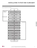
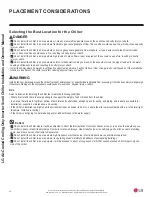
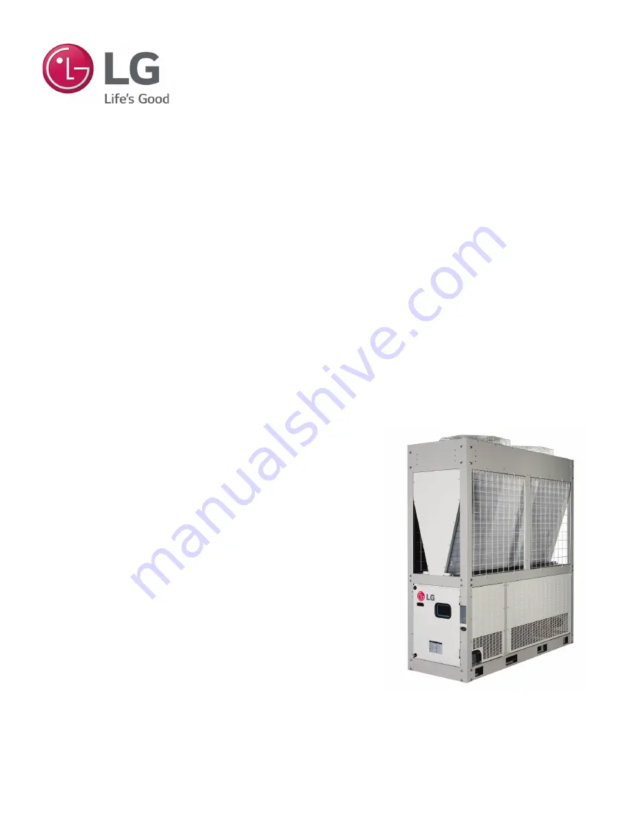
background image

INSTALLATION AND 

OWNERS MANUAL

LG AIR-COOLED  

COOLING ONLY  

INVERTER SCROLL CHILLER 

Cooling Only

20 Tons, 460V Model

Summary of Contents for ACAH020HETB

Page 1: ...INSTALLATION AND OWNERS MANUAL LG AIR COOLED COOLING ONLY INVERTER SCROLL CHILLER Cooling Only 20 Tons 460V Model ...

Page 2: ...reference Content familiarity is required for proper installation The instructions included in this manual must be followed to prevent product malfunction property damage injury or death to the user or other people Incorrect operation due to ignoring any instructions will cause harm or damage The level of seriousness is classified by the symbols described by the summary list of safety precautions ...

Page 3: ...Limit 14 Installation to Test Run Flowchart 15 Placement Considerations 16 20 Transporting Lifting 21 Storing Chiller Installing Anti Vibration Anchor Bolts 22 Water Pipe System Piping 23 25 Freezing Precautions 26 Water Pipe Installation Pump Control 27 Water Quality Management 27 RQWURO 3DQHO RQÀJXUDWLRQ 28 Button Locations and Functions 29 Optional Settings 30 Chiller Address Settings 31 HMI Sc...

Page 4: ...es have been bypassed or are forced to operate LPSURSHUO RU SDUWV RWKHU WKDQ WKRVH VSHFL HG E DUH XVHG WKHUH LV ULVN RI UH HOHFWULF VKRFN H SORVLRQ DQG SK VLFDO LQMXU RU GHDWK Replace all control box and panel covers If cover panels are not securely installed dust water and animals will HQWHU WKH RXWGRRU XQLW FDXVLQJ UH HOHFWULF VKRFN DQG SK VLFDO LQMXU RU death Always check for system refrigerant...

Page 5: ...RQ FDQ FDXVH ZDWHU WR OHDN FDXVLQJ D VOLSSHU VXUIDFH condition and or water damage Always check for system refrigerant leaks after the unit has been installed or serviced RZ UHIULJHUDQW OHYHOV ZLOO FDXVH SURGXFW IDLOXUH Do not make refrigerant substitutions Use only the refrig HUDQW VSHFL HG LQ WKLV PDQXDO I D GLIIHUHQW UHIULJHUDQW LV XVHG RU DLU PL HV ZLWK RULJLQDO UHIULJHUDQW WKH unit will malfu...

Page 6: ...QHFWLRQV ZLOO JHQHUDWH KHDW FDXVH D UH and physical injury or death Ensure the system is connected to a dedicated power source that provides adequate power I WKH SRZHU VRXUFH FDSDFLW LV LQDGHTXDWH RU WKH HOHFWULF ZRUN LV QRW SHUIRUPHG SURSHUO LW ZLOO UHVXOW LQ UH HOHFWULF VKRFN SK VLFDO LQMXU RU death Properly tighten all power connections RRVH ZLULQJ ZLOO RYHUKHDW DW FRQQHFWLRQ SRLQWV FDXVLQJ D U...

Page 7: ...Q RU ÀDPPDEOH JDVHV 8VLQJ WKHVH VXEVWDQFHV ZLOO FDXVH UH H SORVLRQ DQG SK VLFDO LQMXU RU GHDWK If refrigerant leaks ventilate the area before operating the unit If the chiller is mounted in an enclosed low lying or poorly ventilated DUHD DQG LW GHYHORSV D UHIULJHUDQW OHDN LW ZLOO FDXVH D UH HOHFWULF VKRFN H SORVLRQ SK VLFDO LQMXU RU GHDWK To avoid physical injury use caution when cleaning or servi...

Page 8: ...reserved LG is a registered trademark of LG Corp UNIT NOMENCLATURE AC A 020 H H T Evaporator T Direct Exchange Type DX Type Shell and Tube Power Specifications H 460V 60 Hz 3Ø Capacity RT 020 20 RT Compressor Type R Low Pressure Scroll H High Pressure Scroll Cooling Type A Air Cooled Cooling Only W Water Cooled Cooling Only H Air Cooled Heat Pump K Water Cooled Heat Pump Family AC R410A Chiller E ...

Page 9: ...ycle ACAH chillers feature high pressure type scroll compressors The suction vapor is separated from the high pressure discharge area and the motor is installed on the low pressure vapor area The motor and refrigerant storage are located in the low pressure vapor area to increase liquid compression reliability Because the suction refrigerant vapor cools the motor and flows onward to the compressor...

Page 10: ...n for the bearing to help the compression of the refrigerant During this time the refrig erant is compressed and is discharged to the air cooled condenser Ϳ The compressed refrigerant passes through the air cooled condenser and exchanges the heat with the outdoor air The condensed refrigerant then passes the condenser to be overcooled ĺ ĺ The refrigerant that passed through the condenser expands i...

Page 11: ...nt Water psi 609 145 Water Flow Rate Standard gpm 49 Water Flow Rate Min Max gpm 34 64 Water Pipe Inlet Outlet Dia Inch 2 2 Fan Motor Type Brushless Digitally Controlled No of Fans Each 2 No of Vanes per Fan Each 6 Air Flow Rate cfm 8 687 x 2 1 000 rpm Motor Power W 900 x 2 Other Expansion Unit Electronic Expansion Valve Weight lbs 1 235 Dimensions W x H x D Inch 30 1 8 x 86 5 8 x 84 13 16 Footpri...

Page 12: ...g Only Chiller Voltage Range Power supplied to the chiller must fall within the voltage minimum to maximum range listed in the table above The chiller will not operate normally if the power supply voltage falls below or above the tolerance range Maximum allowable voltage variance permitted between phases is 2 MCA Minimum Circuit Ampacity A Criteria used to select the wiring standard MFA Maximum Fu...

Page 13: ...ronics U S A Inc Englewood Cliffs NJ All rights reserved LG is a registered trademark of LG Corp DIMENSIONS Figure 4 Dimensions for Single 460V Cooling Only Chiller D B C A E F G Water Outlet 2 inches 50 A Water Inlet 2 inches 50 A Front B k Side Unit Inch Label Dimensions 30 1 8 86 17 32 86 5 8 84 13 16 19 31 32 27 9 16 15 1 8 ...

Page 14: ...cooled condenser Air cooled condenser Oil separator Oil Separator Sub cooler Water out Water in Accumulator Accumulator Compressor 1 Sub cooler Operation Range and Limit The table and the diagram shows the operation range of the product R QRW RSHUDWH WKH H FHHG WKH RSHUDWLRQ UDQJH RI the chiller Refrigerant Piping and Sensor Diagram Figure 5 Cooling Mode Operation Range Diagram 4 F 14 32 F 50 F 68...

Page 15: ...llation Test Operation Instruction and installation of base following IOM and all applicable codes Delivery and Installation Wiring and Piping Set Control Address Check before Initial Start Check During and After Initial Start Stop Load Operation and Operation Adjustment Prepare Operation Data Analyze Water Quality Guide Operation End Lorem ipsum INSTALLATION TO TEST RUN FLOWCHART Figure 7 Install...

Page 16: ...eath WARNING Install a fence or barricade around the chiller to prevent animals and or unauthorized individuals from accessing it Install a boundary or danger sign LI QHFHVVDU DPDJH WR WKH FRPSRQHQWV FRXOG FDXVH UH H SORVLRQ SK VLFDO LQMXU RU GHDWK Do s Select a location for installing the chiller that meets the following conditions Where it is flat and there is enough strength to support the weig...

Page 17: ...OOHU LV LQVWDOOHG LQ DQ DUHD ZKHUH LW ZRXOG EH GLUHFWO H SRVHG WR RFHDQ ZLQGV DGGLWLRQDO DQWL FRUURVLRQ WUHDWPHQW ZLOO QHHG WR EH DSSOLHG WR WKH FKLOOHU FRQGHQVHU 2FHDQ ZLQGV ZLOO FDXVH FRUURVLRQ SDUWLFXODUO RQ WKH FRQGHQVHU ZKLFK LQ WXUQ FRXOG FDXVH SURGXFW PDOIXQFWLRQ RU LQHI FLHQW performance If the chiller must be placed in a location where it would be subjected to direct ocean winds install a...

Page 18: ...2 inches and the total wall height Installing Under a Ceiling If the chiller is installed under a ceiling the clearance space between the top of the chiller and the ceiling must be a minimum of 197 inches If the front or back of the chiller is near a wall the clearance space between the chiller and the wall must be a minimum of 32 inches Ventilation Clearance Requirements Air cooled chillers must ...

Page 19: ... Chiller Figure 11 Service Clearance Requirements for Two Chillers Service Space Min 36 Min 71 Min 32 Min 32 Unit Inches Location where the water pipes are installed Ensure that there is sufficient clearance space for future service mainte nance and repair Min 71 Min 36 Min 32 Min 32 Min 24 Service Space Unit Inches Location where the water pipes are installed Ensure that there is sufficient clear...

Page 20: ...m of snow has accumulated on top of the chiller remove the snow and then operate the unit 5 The height of the concrete slab or base materials plus spring isolation should not exceed the width of the chiller 6 Do not install the chiller in an area where heavy snow accumulation could negatively impact chiller operation Position the chiller in such a way that the side with the air heat exchanger does...

Page 21: ...DFNDJLQJ VR WKDW FKLOGUHQ GR QRW SOD DQG ULVN VXIIRFDWLRQ DQG GHDWK LIW DQG VXSSRUW WKH FKLOOHU DW VSHFLILHG ORFDWLRQV DW OHDVW IRXU SRLQWV WR DYRLG VOLSSLQJ IURP WKH ULJJLQJ DSSDUDWXV DQG WKH DSSURSULDWH OHQJWK IHHW G DQG QXPEHU RI OLIWLQJ VWUDSV 7KHUH LV D ULVN RI WKH SURGXFW IDOOLQJ DQG FDXVLQJ SK VLFDO LQMXU 8VH FDXWLRQ ZKHQ XVLQJ IRUNOLIW WR WUDQVSRUW WKH FKLOOHU R QRW GURS WKH XQLW ZKHQ FDUU...

Page 22: ...d WARNING Improper installation will cause the unit to fall over resulting in physical injury or death Improper installation can cause product malfunction and damage 6725 1 7 5 167 1 17 VIBRATION AND ANCHOR BOLTS Installing Anti Vibration Use field supplied anti vibration and install before placing the chiller on the base or its installation area Anti vibration is required and is to be specified a...

Page 23: ...emains in the water pipes water pipe system resistance increases and or the amount of circulating water is reduced significantly If air remains in the pump during operation it can result in chiller malfunction or shutdown Install an air vent valve where there could be a chance of air remaining in the water pipe system Include 1 200 of slope on the air vent valve side to reduce the likelihood of ai...

Page 24: ... A Recommended Independent product installation LG Supplied P1 T1 T2 P2 LG Supplied P2 T2 P1 T1 Leaving Cold Water Entering Water Symbol Description Symbol Description Provided by Others Valve 100 Flow T1 or T2 Temperature Sensor 1 Inlet 2 Outlet Strainer 50 Mesh P1 or P2 Pressure Gauge 1 Inlet 2 Outlet Flexible Joint Cold Water Pump Pump Sized to Meet Minimum to Maximum Flow for LG Chiller Servic...

Page 25: ...G Supplied Leaving Cold Water Entering Water Installation Method B Independent product installation Figure 19 Installation Method B Symbol Description Symbol Description Provided by Others Valve 100 Flow T1 or T2 Temperature Sensor 1 Inlet 2 Outlet Strainer 50 Mesh P1 or P2 Pressure Gauge 1 Inlet 2 Outlet Flexible Joint Cold Water Pump Pump Sized to Meet Minimum to Maximum Flow for LG Chiller Serv...

Page 26: ...tem Add anti freeze to prevent the circulation water from freezing during the winter season if design temperature is below 41 F Maintain water flow following design specifications to reduce damage from rusting scaling and corrosion LG is not responsible for any chiller damage resulting from poor water quality management or improper water processes Inlet Water Pipe Drain Hole Drain Hole Inlet Water...

Page 27: ...below Sulfur Ion ppm Must not be detected Must not be detected Ammonium Ion ppm 0 5 or below 0 2 or below Silica ppm 50 or below 30 or below Table 4 Chiller Water Standards Water Pipe Installation SSURSULDWH SUHVVXUH RI WKH SLSH IODQJH FRQQHFWLRQ LV SVL 03D Water pipe size must be the same or larger than that of the chiller To prevent the water pipe connections from sagging due to the load install...

Page 28: ...ace HMI Use for basic product setting and commands displays product information and information for each cycle Main Controller Controls the input output port and communicates with each cycle Power Supply Supplies power to the HMI MCCB Molded Case Circuit Breaker MCCB Shuts off the overcurrent Line or High Voltage Terminal Block The terminal block that receives the external main power Main Controll...

Page 29: ...tton Locations Button Name Description SW_RIGHT Changes the Setting SW_LEFT SW_UP Moves the Screen SW_DOWN SW_CONF Sets the Selected Function SW_BACK Returns to the Previous Step The controller includes the buttons described below to set the functions listed in the table without using the HMI SW_CONF SW_LEFT SW_UP SW_BACK SW_RIGHT SW_DOWN BUTTON LOCATIONS AND FUNCTIONS Table 6 Button Function Tabl...

Page 30: ...ate the chiller and STOP to stop the operation Heating Cooling HEAT COOL Sets the cooling heating operation mode COOL selects cooling mode and HEAT selects heating mode Cooling Setpoint Temperature 7 Sets cooling target temperature 39 2 F 68 F Load Outflow Water Temperature Shows the temperature value of load outflow water Specified in 0 level Control Mode LOC DIST SCHE Sets the product s control ...

Page 31: ...the Address on the Main Controller 1 3UHVV WKH GRZQ DQG ULJKW EXWWRQV ź Ź VLPXOWDQHRXVO 2 When FN02 appears press SW_CONF button 3 6HOHFW WKH GHVLUHG DGGUHVV XVLQJ WKH OHIW RU ULJKW Ż Ź EXWWRQV KHQ WKH GHVLUHG IXQFWLRQ GLVSOD V SUHVV 6 B 21 EXWWRQ WR VHW 4 To cancel press the SW_BACK button No Description Screen Display 0 Level Screen Display 1 Level 1 Chiller Address F N 0 2 1 CHILLER ADDRESS SET...

Page 32: ... HMI screen Logging in to the HMI When power is applied to the HMI the HMI operates automatically When the HMI initiates the home screen appears Introduction to the HMI Menu HMI Main Screen Configuration After logging into the HMI the system view screen displays the typical information of the chiller Icon Description Displays the load water temperature pump flow amount status and system informatio...

Page 33: ...follows According to the outdoor air temperature condition the load water pump repeats operation ON and OFF 2XWGRRU LU 7HPSHUDWXUH ĺ OZD V 21 2XWGRRU LU 7HPSHUDWXUH ĺ WZR PLQXWH RSHUDWLRQ DQG HLJKWHHQ PLQXWH VWRS 2XWGRRU LU 7HPSHUDWXUH ĺ 2SHUDWLRQ 2 The freeze and burst prevention mode is possible when the pump is connected To interface with the pump the pump output connect is to be installed To v...

Page 34: ...ller View Chiller Information System Information Screen Table 10 Pump Flow Amount Status Screen Table HMI SCREENS Operation Information Chiller Control Sets the Start Stop On Off Set Temperature Operation Mode Only for Heat Pump Models Control and Maximum Operating Frequency Icon Description Selects the start and stop signal command of the chiller Sets the target temperature value for the current ...

Page 35: ...e After the area where the chiller control s set temperature display is pressed a pop up window to input the setting temperature appears In the temperature setting pop up window change the temperature using the up down arrows After the temperature setting display area is pressed input the setting temperature input using the numer ic keyboard After changing the temperature setting press Apply to re...

Page 36: ... the previous setting Icon Description Manual control mode through HMI If the schedule mode is set manual and remote control are not possible and only the start stop by the schedule is possible ON OFF is only possible by the chiller controller s Remote Start signal ON OFF is only possible by the external MODBUS communication HMI SCREENS Figure 37 Control Mode Screen Table 12 Control Mode Screen Ta...

Page 37: ...Displays the currently selected cycle Selects the cycle information and the cycle temperature Displays the hot gas valve status Shows the sump heater status Icon Description Displays the inverter compressor s operation frequency value Displays the current EEV pulse signal value Displays the current high pressure value Displays the current low pressure value HMI SCREENS Figure 39 Cycle Information ...

Page 38: ...cle condensation temperature value Displays cycle evaporation temperature value Cycle Information Screen Composition Current Cycle Operating Screen Cycle Information Screen Composition Current Cycle Temperature Screen Part 1 Figure 42 Current Cycle Temperature Screen Part 1 HMI SCREENS Table 15 Current Cycle Operating Screen Table Icon Description Displays cycle compressor discharge temperature va...

Page 39: ...o operate the chiller schedule In Home screen if you press the schedule icon the schedule screen appears To enter the schedule screen press the Schedule button in the HMI Main Screen Icon Description Checks the monthly set schedule at a glance Checks the start time of the schedule and the set operation mode Check the set schedule in a list HMI SCREENS Figure 44 Schedule Menu Month Figure 45 Schedu...

Page 40: ...ing is maintained Press the Date area and a pop up window to set the date appears Set the start and end dates to use the schedule operation function and the press Apply button If the Cancel button is pressed the previ ous setting is maintained Press the Time area an a pop up window to set the time appears Set the time to use the schedule operation function and press the Apply button If Cancel butt...

Page 41: ...ined Press the Setting Temperature area and a pop up window to input the temperature setting appears Set the temperature and press the Apply button If the Cancel button is pressed the previous setting is maintained Press the ON OFF area and a pop up window to select ON OFF appears Choose ON or OFF for the schedule operation function and press the Apply button If the Cancel button is pressed the pr...

Page 42: ...ting is maintained HMI SCREENS Schedule Menu Composition Edit Schedule 1 In the View Schedule _ List screen select the schedule to edit 2 After the pop up window of the selected schedule appears press the buttons listed in the table below to set Figure 58 Operation Screen After Information is Set Icon Description Pop up window stating Do you want to delete the selected schedule appears and when th...

Page 43: ... appears Select a list to active the Delete button After the Delete button is activated and when the Delete button is pressed the selected list will be removed Schedule Menu Composition Schedule List Edit 1 In the View Schedule _ List screen press the Edit button at the top right side 2 When the Edit screen appears edit and delete the schedule addition and lists as necessary HMI SCREENS Figure 61 ...

Page 44: ...ed by selecting day week and month Report Menu Composition Detail Information Select a history to view in detail and the Detail Information pop up window appears The date time address code and the information of the error code appears When OK is pressed the pop up window disappears Report Menu Composition Delete History When the Clear button at the top side of the Error Screen is pressed a pop up ...

Page 45: ...tting Menu Composition Device From the Setting Screen press the Device Icon and the Device Screen appears Icon Description Edit Unit Address Sets chiller address and number of chiller units Initial chiller address and number is one 1 For automatic control or ACP MODBUS communication and HMI interface if the chiller s Main PCB address is changed the chiller s HMI address must changed set as the sam...

Page 46: ...intained HIDXOW YDOXH LV RQH WKH PD LPXP QXPEHU WR VHW DQG XVH LV five 5 Setting the chiller address The chiller address must match in both the main PCB of the chiller and the HMI If the two addresses do not match it will cause an HMI communication error If the HMI address is reset while the chiller is operating a commu nication error will occur and the chiller will stop operating Reset the addres...

Page 47: ... the default If it is necessary to apply Use again press Use OFF input password and then press the Apply button Initial password digital21 2 Change password When the Change Password area is pressed the Change Pass word window appears Input Current P W New P W and Re type P W and press the Apply button I WKH ZURQJ SDVVZRUG LV LQSXWWHG YH WLPHV FKHFN ZKHWKHU WR LQLWLDO ize the password If the Cancel...

Page 48: ...zing capacity of 20RT or higher Set the condensation temperature at which the spray function works Sets the outdoor air temperature at which the spray function works Press the Condensing Temperature Water Spray or the Outdoor Air Temperature Water Spray icons to display the screens below Range of condensing temperature settings 72 F to 108 F 40 C to 60 C Range of outdoor air temperature settings 3...

Page 49: ...htness according to the ambient illumination intensity Figure 80 Screen Window Table 23 Screen Window Table HMI SCREENS View Setting Menu Composition Screen Screen Saver Press the Screen Saver area on the Screen window to display the Screen Saver window 1 Press the area on the left side to Use or Not Use the screen saver Whenever that area is pressed the selected value is changed 2 Select Use to a...

Page 50: ...ntained Screen saver waiting time Figure 84 Screen Saver Wait Time Window Figure 85 Monitor Power Off Screen View Setting Menu Composition Screen Monitor Power Off When the Screen Power Saving area is pressed the Screen Power Saving window appears Select the time and then press the Apply button If the Cancel button is pressed the previous setting is maintained View Setting Menu Composition Screen ...

Page 51: ...perate based on the set date Selected the base valve of the time recognized by the chiller Thee time display and the schedule interface time etc operate based on the set time Input and edit the controller s name The applied name is displayed at the top left side of Main Screen Selects whether to use touch sound Selects the temperature unit to be displayed on the controller Select from C or F Selec...

Page 52: ...he Controller Name Edit area The Controller Name Edit window appears Input the desired controller name and then press the Apply button to set If the Cancel is button pressed the previous setting is maintained Figure 90 Controller Name Edit Screen View Setting Menu Composition System Normal Speaker On the System Normal screen when the Speaker area is pressed it switches between On and Off Separate ...

Page 53: ...Menu Composition System Normal Language On the System Normal screen press the Language Setting area The Language window to set the language appears Select the desired language and press the Apply button to set If the Cancel is button pressed the previous setting is maintained HMI SCREENS Figure 93 Language Screen Figure 94 Advance Screen View Setting Menu Composition System Advance On the Setting ...

Page 54: ...RSHQ VRXUFH FRGHV GHYHO RSHG XQGHU 3 3 03 RU RWKHU RSHQ VRXUFH OLFHQVHV LQVWDOOHG LQ this chiller The open source codes as well as the contents of all applicable licens es copyright notice and warranty disclaimers are downloadable HMI SCREENS View Setting Menu Composition System Advance Version Information On the System Advance screen press the Version Information area A pop up window that display...

Page 55: ...eft right direction buttons to check the information for each interfaced chiller Chiller Interface Control Operation Total Through the Chiller Operation_Total screen the same operation con dition can be set for all the chillers For individual control press the left right direction buttons but Con trol Mode or Run Mode cannot be changed Chiller Interface Control Cycle Information The cycle informat...

Page 56: ...K ZLOO FDXVH ERGLO LQMXU RU GHDWK Properly ground the chillers R QRW FRQQHFW JURXQG ZLUH WR UHIULJHUDQW JDV RU ZDWHU SLSLQJ WR OLJKWQLQJ URGV WR WHOHSKRQH JURXQG ZLULQJ RU WR WKH EXLOGLQJ SOXPELQJ V VWHP URXQG ZLULQJ PXVW DOZD V EH LQVWDOOHG E D TXDOLILHG WHFKQLFLDQ DLOXUH WR SURSHUO SURYLGH D 1 DSSURYHG HDUWK JURXQG FDQ UHVXOW LQ HOHFWULF VKRFN SK VLFDO LQMXU RU GHDWK 3URSHUO JURXQG WKH DOO FKLOO...

Page 57: ...DQ JHQHUDWH D ILUH HOHFWULF VKRFN SK VLFDO LQMXU DQG RU GHDWK Install the power wiring only after the ring terminal is connected Improper connections can damage electrical components 9HULI WKH SRZHU LPEDODQFH LV QR JUHDWHU WKDQ EHWZHHQ SKDVHV DW HDFK XQLW 3RZHU LPEDODQFHV ZLOO GDPDJH WKH FRPSUHVVRUV DQG RWKHU components WARNING OO SRZHU ZLULQJ DQG FRPPXQLFDWLRQ FDEOH LQVWDOODWLRQ PXVW EH SHUIRUPHG...

Page 58: ...mparted to the terminal block Use an appropriately sized screwdriver for tightening the terminals Do not overtighten the connections overtightening will damage the terminals If ring terminals or fork terminals are not available then Do not terminate different gauge wires to the power terminal block Slack in the wiring will generate heat When terminating wires of the same thickness follow the instr...

Page 59: ...lded cable for communication Ensure the communication cable shield is properly grounded to the Chiller chassis only If one conductor cable is used it will result in poor communication quality 2 Use only the regulated communication cable Do not use multiple lines It can cause communication errors Do not install the communication cable parallel to the power wiring It can cause communication errors W...

Page 60: ... Status DO DO2 Optional Field Installed Pump Output DO DO3 Optional Field Installed Heater Output DO DO5 Optional Field Installed Table 29 Field Installed Wiring Cable Connections Table 28 Power Wiring System to Multiple Grouped Chillers Circuit Breaker Circuit Breaker Circuit Breaker Main Power Supply Circuit Breaker Main Power Supply Cir Main y Refer to the wiring diagram for field installed wir...

Page 61: ...C Ɣ RQILUP SW01D Reset Table 30 Setting the Control Box Address Cycle Address SW01B DIP Switch Setting Cycle Address No 1 DIP Switches Nos 6 and 7 to OFF SW01B If there is only one 1 cycle PCB connected to the chiller s main controller Cycle Address No 1 must be used or the chiller will not operate When replacing the cycle PCB always run the automatic address setting procedure again Automatic addr...

Page 62: ... back of the panel 4 Connect the cable to the communication port located on the back of the HMI LIIHUHQW SRODULWLHV H LVW RQ WKH FRPPXQLFDWLRQ FDEOH do not PL W ZLOO UHVXOW LQ D ILUH HOHFWULF VKRFN DQG ZLOO UHVXOW LQ GDPDJH to the compressors and other components 7R SUHYHQW LPSURSHU FRQQHFWLRQV PDUN DQG LW LV UHFRP PHQGHG WR PDUN DQG RQ WKH FRPPXQLFDWLRQ FDEOH DLOXUH WR GR so will result in a comm...

Page 63: ...Ensure the communication cable shield is properly grounded to the chiller chassis only Do not ground the communication cable at any other point Wiring must comply with all applicable local and national codes 4 Install the communication cable and power wiring separately so that communication cable is not impacted by any electric noise generated from power wiring Do not install the power wiring and ...

Page 64: ...KHQ FRP munication is recovered it will automatically resume If the remote Modbus connection is not used reset the power of the main PCB of the chiller to cancel the alarm Modbus Interlock Protocol Details The protocol details for Modbus interlock of external devices are Physical layer RS 485 serial line Mode Modbus RTU mode Baud rate 9 600 Parity None parity One 1 stop bit Applied function codes ...

Page 65: ...1 1 4 Way Valve 2 On of Cycle 1 10107 0 Hot gas1 Off of Cycle 1 1 Hot gas1 On of Cycle 1 10108 0 Hot gas2 Off of Cycle 1 1 Hot gas2 On of Cycle 1 10109 0 Sump Heater 1 Off of Cycle 1 1 Sump Heater 1 On of Cycle 1 10110 0 Sump Heater 2 Off of Cycle 1 1 Sump Heater 2 On of Cycle 1 10111 10118 Reserve 10119 0 Inverter Compressor 1 Off of Cycle 1 1 Inverter Compressor 1 On of Cycle 1 10120 0 Inverter ...

Page 66: ...essor 1 Off of Cycle 2 1 Inverter Compressor 1 On of Cycle 2 10224 0 Inverter Compressor 2 Off of Cycle 2 1 Inverter Compressor 2 On of Cycle 2 10225 10312 Reserve 10313 0 4 Way Valve 1 Off of Cycle 3 1 4 Way Valve 1 On of Cycle 3 10314 0 4 Way Valve 2 Off of Cycle 3 1 4 Way Valve 2 On of Cycle 3 10315 0 Hot gas1 Off of Cycle 3 1 Hot gas1 On of Cycle 3 10316 0 Hot gas2 Off of Cycle 3 1 Hot gas2 On...

Page 67: ...el 30015 30100 Reserve 30101 30102 Load Water Output Temperature of Cycle 1 30103 30104 Load Water Input Temperature of Cycle 1 30105 30108 Reserve 30109 Condensation Temperature Left of Cycle 1 30110 Condensation Temperature Right of Cycle 1 30111 Evaporation Temperature Left of Cycle 1 30112 Evaporation Temperature Right of Cycle 1 30113 Inverter Compressor 1 Frequency of Cycle 1 30114 Inverter ...

Page 68: ...tion Temperature Left of Cycle 2 30212 Evaporation Temperature Right of Cycle 2 30213 Inverter Compressor 1 Frequency of Cycle 2 30214 Inverter Compressor 2 Frequency of Cycle 2 30215 High Pressure Left of Cycle 2 30216 High Pressure Right of Cycle 2 30217 Low Pressure Left of Cycle 2 30218 Low Pressure Right of Cycle 2 30219 Operation Current Left of Cycle 2 30220 Operation Current Right of Cycle...

Page 69: ...mpressor 1 of Cycle 3 30326 Discharge Temperature of Inverter Compressor 2 of Cycle 3 30327 Intake Temperature of Inverter Compressor 1 of Cycle 3 30328 Intake Temperature of Inverter Compressor 2 of Cycle 3 30329 Liquid Pipe Temperature Left of Cycle 3 30330 Liquid Pipe Temperature Right of Cycle 3 30331 Hex Temperature Left of Cycle 3 30332 Hex Temperature Right of Cycle 3 30333 30344 Reserve 30...

Page 70: ...peration Check if the load is operating on the air processing device or any other device on the water supply side to the chiller If the temperature of the water is too high the initial operation of the load device can be delayed If the chiller auto control is not working check if the water circulation pump is operating Voltage variance must be within 10 Check that the phase voltage imbalance is no...

Page 71: ...s not used turn the DIP switch OFF and reset the power If the chiller RPM is changed the cooling capacity may be reduced Step Maximum Fan RPM Standby Time Hour Function Operation Time Hour 1 1 820 8 9 2 6 5 10 5 3 5 12 4 2 750 8 9 5 6 5 10 5 6 5 12 7 3 720 8 9 8 6 5 10 5 9 5 12 10 820 0 Continuous Operation 11 750 0 Continuous Operation 12 720 0 Continuous Operation DIP SW01 7 Segment SW04C X canc...

Page 72: ...e HMI screen but the current error code status is maintained Error Code The error code is configured as below HMI Communication Error OK 3URFHVV ODUP UURU Common Error CH10XXX error stops product operation Error By Cycle When the error occurs by cycle the applicable cycle is maintained at stopped condition and normal cycles operate normally When the cycle error is canceled the chiller resumes norm...

Page 73: ...res below one 1 time per year Check if a service port is mounted on the water pipe for solvent cleaning A 5 diluted formic acid citric acid oxalic acid water acid acetic acid phosphoric acid etc are suitable as the solvent for scale cleaning R QRW XVH GURFKORULF DFLG VXOIXULF DFLG QLWULF DFLG HWF 7KHVH VROYHQWV KDYH FRUURVLYH SURSHUWLHV WKDW ZLOO GDPDJH WKH KHDW H FKDQJHU During the cleaning proce...

Page 74: ... heat exchanger may freeze and burst Check if the strainer is blocked or filled with air Measure the temperature and or pressure differences between the inlet and outlet water piping If there is a difference of temperature or pressure above the appropriate levels the water flow has decreased Immediately stop chiller operation troubleshoot and fix the issue before restarting If there is air in the ...

Page 75: ... and or water quality conditions HIRUH KHDW H FKDQJHU FOHDQLQJ UHPRYH SDUWV VXFK DV SUHVVXUH JDXJHV RU VKXW RII WKH YDOYHV VR WKDW VROYHQWV FDQQRW HQWHU KHFN WKH SLSLQJ FRQQHFWLRQV LQ DGYDQFH RI H FOHDQLQJ WR SUHYHQW VROYHQW OHDNV HJLQ FOHDQLQJ DIWHU WKH VROYHQW DQG ZDWHU DUH PL HG WKRURXJKO QLWLDWH KHDW H FKDQJHU FOHDQLQJ LQ WKH EHJLQQLQJ RI WKH FKLOOHU V OLIH F FOH I VFDOH DFFXPXODWLRQ EHFRPHV V...

Page 76: ...s Symptom Cause Solution Chiller does not start Check the power Check over current protection device Check if fuse is disconnected or shorted out Turn power on Incorrect or inaccurate chiller configuration Check configuration Check if wiring is incorrect Error appears Check the error condition Check for the error code tables to review solutions and resolve the issue Follow direction Check the HMI ...

Page 77: ...ard near compressor Replace the anti vibration material on piping High frequency wave sound from front of chiller Fan defect in the control box Clean the area around the fan Constantly searching for cold water Insufficient cold water Check the water system Ensure rated flow Is the water system valve closed Is the pressure difference between inlet and outlet of the water system appropriate Is the a...

Page 78: ...n 1 hour Stop product Press the HMI Reset button CHxx013 Load water flow switch error When the load water flow switch is turned off for 3 seconds when starting or during the operation for more than 3 times within 1 hour When turned off more than 9 seconds within 1 hour Stop product Press the HMI Reset button CHxx015 Remote alarm When the contact point signal of hardware wiring is short when enteri...

Page 79: ...e sensor is disconnected shorted or opened Stop applicable cycle Automatically return to normal condition CHxx050 Chiller 3 phase power missing phase Chiller 3 phase power missing phase Stop applicable cycle Automatically return to normal condition CHxx052 Communication error with inverter controller Communication error with inverter controller Stop applicable cycle Automatically return to normal ...

Page 80: ...CHxx113 Liquid pipe temperature sensor error Liquid temperature sensor is disconnected shorted or opened Stop applicable cycle Automatically return to normal condition CHxx114 Sub cooling suction temperature sensor error Sub cooling suction temperature sensor is disconnected shorted or opened Stop applicable cycle Automatically return to normal condition CHxx115 Sub cooling outlet pipe temperature...

Page 81: ...mark of LG Corp 2 Model Information Content Information Product Model Name Model Name Model Name Serial Serial Serial Compressor A Model Name Model Name Model Name Serial Serial Serial Compressor B Model Name Model Name Model Name Serial Serial Serial 1 Project Information Content Information Project Name Address Installed by Sold by Test run by Checklist for Chiller Installation Page 1 of 2 ...

Page 82: ...ed correctly in accordance with specifications and codes Yes No Are all the terminal blocks connected properly Yes No Are all control plugs connected properly and seated at the terminal boards Yes No 4 Check Water System Content Check Are all valves connected to the chiller open Yes No Are all pipes connected accurately Yes No Are there any clogs in the drain pipe Yes No Are there any leaks Yes No...

Page 83: ...tional technical documentation visit www lghvac com LG Electronics U S A Inc Air Conditioning Technologies 4300 North Point Parkway Alpharetta Georgia 30022 www lghvac com New Issue IOM_Chiller_CoolingOnly_460V_06_21 ...

Reviews: